2D meshing on the instrumental Panel in ANSA
2D meshing on the instrumental Panel
Aim: To create the Midsurface and Mesh the given Instrument Panel according to the Quality Criteria given below. Also Thickness is to be assigned to the mesh.
Quality Criteria:
|
S.No |
Quality Criteria |
Value |
|
1 |
Target/Average length |
4 |
|
2 |
Minimum Length |
2 |
|
3 |
Maximum Length |
6 |
|
4 |
Aspect |
3 |
|
5 |
Warpage |
15 |
|
6 |
Skewness |
45 |
|
7 |
Jacobian |
0.7 |
|
8 |
Minimum Quad Angle |
45 |
|
9 |
Maximum Quad Angle |
135 |
|
10 |
Minimum Tria Angle |
30 |
|
11 |
Maximum Tria Angle |
120 |
|
10 |
Tria Percentage |
15 |
1. INTRODUCTION: About the Instrument Panel.
- The given component is the instrument panel of a car.(refer image 1.1)
- It is made of plastic and its thickness is non-uniform over the entire component.
- There are three types of plastic used in the Automobile industry. They are
- Polyurathene plastic
- Polypropylene plastic
- Poly vinyl chloride(PVC)
- There are other types of plastic used in the automobile industry other than above three types of plastic.
- They are ABS plastic, polystyrene, polycarbonate, PMMA, etc.
- Image 1.1 shows the image of the Instrument panel.
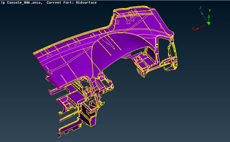
Image 1.1 Instrument panel.
2. FEATURES: Instrument panel.
The features of the instrument panels are shown below
- Slots for the attachment of Instrument Cluster, AC vents, Infotainment system etc.
- Ribs to strengthen the plastic instrument panel.
3. PROCEDURE: To create midsurface, mesh and assigning thickness.
The stages in meshing the component
- Import the model.
- Create the Midsurface.
- Mesh as per the given Quality criteria.
- Assigning the Thickness to the mesh.
- 2D meshing is made as the thickness of the component is very less(less than 5mm), also creating 3D meshing involves many nodes and elements which consumes more space and requires more time for further analysis.
- Therefore a surface is genrated such that on assigning thickness it ressembles the actual component, this surface is called as Midsurface.
3.1 Importing the Model:
To import the model
File> >Select the Component(Refer the below image)
Image 3.1.1 Importing the model.
3.2 CREATING THE MIDSURFACE
- Midsurface can be generated by two ways; Auto midsurface and Manual midsurface.
- For this component, midsurface is generated using Manual midsurface procedure.
- To create manual midsurface the thickness of the model is to be known.
- To find the thickness find the distance between the two hot points between the top and bottom surface Tools> Measure>Select the two Hot Points.(refer image 3.2.1)
- The average Thickness of the component, excluding the ribs, was found to be 2mm.
- To create midsurface, a new part is to be created where the midsurface is to be placed.
- Then the outer surface is offset to half of the thickness of the component.
- .(refer image 3.2.2)
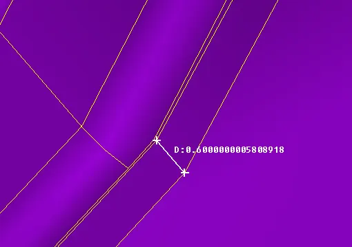
Image 3.2.1 Measuring the distance between two hot points
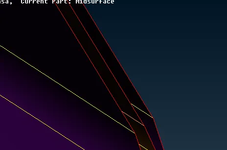
Image 3.2.2 Offsetting the surface
Creating midusrface for ribs
To create midusrface for ribs(refer the below image)
- Create a curve inbetween the edges of the ribs
- Project the curves onto the midsurface
- Create a new surface using these curves an coons.
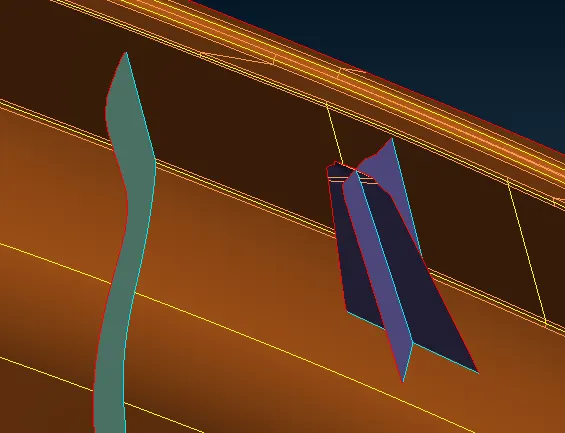
Image 3.2.3 Creation of midusurface of ribs
3.3 GEOMETRY CLEAN-UP OF THE MIDSURFACE
- After attaching the rib surface onto the outer midsurface, it is to be cleaned i.e to remove unnecessary trim lines which will make elements to fail.
- In this midsurface, there are many coons that are unnecessary and is toggled using a cut tool.
- Some of the coos toggled are shown below.
- After toggling surfaces is trimmed using the faces>cut tool to create segments of surface for better mesh flow and quality.
- Some of the trim lines on the midsurface are shown below. (refer to image 3.3.1)
3.4 MESHING THE MIDSURFACE
- To mesh the generated midsurface as per the given quality criteria, first quality criteria is to be set.
- To set the Quality Criteria Values Quality Criteria>Set the values(refer fig 3.4.1)
- Enter the values of the Quality criteria given and save the criteria file for further use.
- Saving the criteria file helps in saving time as it changes to default values on closing the Hypermesh.
- To mesh the surface 2D>Best>select the segments of the midsurface and clear the failed elements side-by-side inorder to get good mesh quality and mesh flow.(refer fig 3.4.2)
- To clear/repair the failed Use cleanup tools such as Reconstruct, Improve, Smooth, Split, Swap, etc. to clean up the mesh.
- The following rules is to follow while meshing
- Feature Capturing
- Mesh flow
- Quality Criteria
- Tria Management
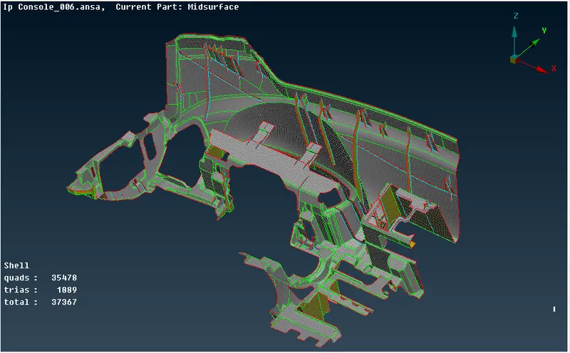
Image 3.4.1 Midsurface Meshed
3.5 APPLYING PROPERTY TO THE MESH
Thickness is assigned to the midsurface after meshing. (refer the below image)
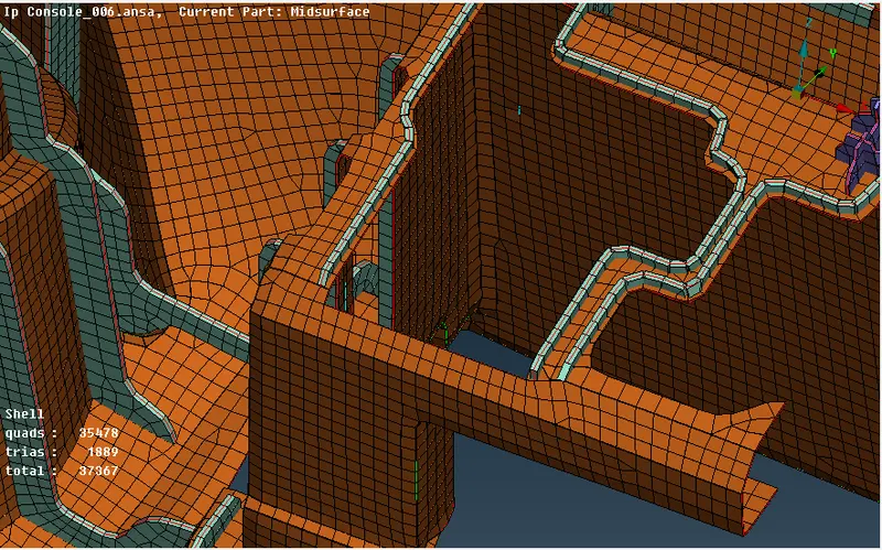
Image 3.5.1 Mesh After adding property
CONCLUSION:
The following operations are performed on the given model.
1. Geometry Clean-up
2. Misdurface
3. Geometry Cleanup of midsurface
4. Meshing with respect to Quality Criteria
5. Assigning thickness