Project 1
Q1.Design the mainline alignment.
Aim & Introduction
The design concept for the mainline alignment can be developed by ORD with minimum requirement such as survey data, proposed right of etc.
Procedure
The procedure for developing the mainline alignment will be explained below.
The procedure for creating the alignment and profile is explained below.
Open ORD => New file=>Seed 2D and Name file as Mainline Alignment
File loads up=>go to attach file by reference attachment=> survey topo.dgn file=>attach the file with surface to grid factor 1:1.00012=> file loads up=>go to Utilities and setup the coordinate system=> now turn off all levels except the existing pavement edges and C/L by the Level display.
Go back to the reference attachment method and attach the existing and proposed ROW files.
Again, go back to the level display and select each model and hide unnecessary data except the existing and proposed edge lines (Please check the line properties before going into Level display)
Go to attributes and click level override to view the lines in white and orange colour.
Now click the space key in the keyboard and MicroStation menu pops up=> now click copy=>select the 1st straight portion (or simple element) near the junction (just after the radius part) move from the base snap point and return and keep it in the same point in order to keep it active.
Now turn off the proposed ROW from the Level display which is very important
Go to complex tools=>click Define by best fit=>window appears=> Best fit=>Complex by edges=>Envelope parameter=>0=>Rounding parameter=>0=>Include spirals=>no=>Default Radius=>3000
Select primary and secondary objects and accept it a new proposed C/L appears in white colour
Now click the C/L and flyout menu appears with and additional option convert to horizontal rules=>click the C/L and accept it
Now turn on the Aerial Image, also turn on the Proposed ROW lines and now go along the line and select any portion with a narrow ROW and repeat the same procedure (Before that Go to Horizontal lines=>window appears =>assign FD=>alignment =>preliminary planning=> Geom tmp.( Do make the temp C/L a complex line before drawing arcs).
Now after creating the new C/L delete both parent lines and repeat the procedure near the end of the road with intersection point. And go to arcs => Arc between elements => Draw new arc matching the alignment C/L.
Now turn on the aerial image and extend both lines till the intersection and check the angle difference between tangents, if its more than 1 degree provide curve to make it smooth. Also after this we want convert the lines into a complex line by complex by element method.
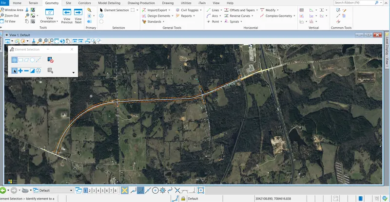
Now go ahead and assign a station value to the alignment.
Go to Drawing=>Modify=>start station=>locate the element=> assign start distance=>go to the start point=>enter the station value 50+00 now the station value has been assigned.
Now turn on Civil toggles=>click station offset=>click on any point on the line it shows the station as zero=> Now go to Civil toggles=>hold on the drop-down menu=>E switch dialogue mode=>new window appears=>pick the C/L line and chainage can be seen as per the cursor movement on the line.
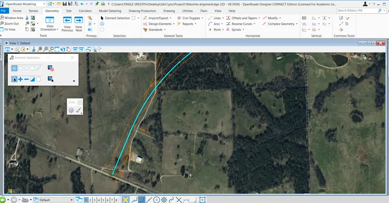
Results
Thus, project mainline alignment can be created
Q2. Create the existing ground profile of the above created alignment. Design the proposed profile for the mainline alignment.
Aim & Introduction
Existing ground profile and proposed profile can be generated with ORD. This will be explained in detail below.
Procedure.
The procedure for creating the existing ground profile and proposed profile has been explained in detail below.
Open ORD => T&E and TI
Browse mainline alignment.dgn=> go to Vertical=> Complex geometry=> Profile => complex by elements=>a small window appears=> method=>select automatic=> FD=>assign active FD and name it as Profile
Go to reference attach window=>attach eterrain file from the Survey folder=>attach with live nesting depth 1=>now click on the view 8 => profile window opens up=> go to view and arrange both models in the same display=>click on the eterrain model and flyout menu appears=>select set as active =>now go to profile window and fit view=> now the actual profile data appears on the screen.
Now, profile for the existing ground has been created.
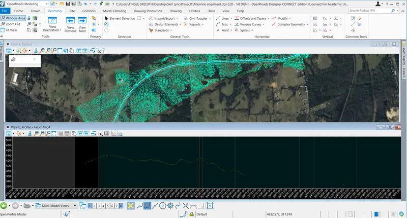
Go to vertical=>complex geometry=>complex by PI=> draw lines as close to the existing ground and edit the curves=> go to curves=>profile curve between elements=>circular curve between elements and make the curves smooth.
If the element has multiple parts, then make it complex by first exploding all elements with Drop element command and then re-joining it with Vertical=> complex geometry=>complex by elements =>assign FD
select vertical profile element=>flyout menu=>set as active profile
Now open Civil accudraw tool=> keep it in the plan view=>drop down menu=> click eswitch dialogue mode=>now the Z value can be seen in the profile window while touching the lowest point.
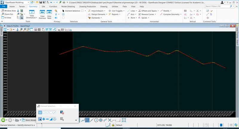
Results.
Thus, the proposed profile for the mainline alignment has been created.
Q3. Design alignments for remaining 4 intersecting streets (use mainline alignment CL to tie in).
Aim & Introduction
Alignments for the intersections can be created with ORD using the various tools available. This will be explained in detail below.
Procedure.
The step-by-step procedure has been explained below.
Open ORD => New file=>Seed 2D and Name file as Mainline Alignment (which created earlier)
Go to element selection and select the EOPs existing of the intersections.
Now click the space key in the keyboard and MicroStation menu pops up=> now click copy=>select the 1st straight portion (or simple element) near the junction (just after the radius part) move from the base snap point and return and keep it in the same point in order to keep it active.
Now turn off the proposed ROW from the Level display which is very important
Go to complex tools=>click Define by best fit=>window appears=> Best fit=>Complex by edges=>Envelope parameter=>0=>Rounding parameter=>0=>Include spirals=>no=>Default Radius=>3000
Select primary and secondary objects and accept it a new proposed C/L appears in white colour
Now click the C/L and flyout menu appears with and additional option convert to horizontal rules=>click the C/L and accept it
Now turn on the Aerial Image, also turn on the Proposed ROW lines and now go along the line and select any portion with a narrow ROW and repeat the same procedure (Before that Go to Horizontal lines=>window appears =>assign FD=>alignment =>preliminary planning=> Geom baseline. ( Do make the temp C/L a complex line before drawing arcs).
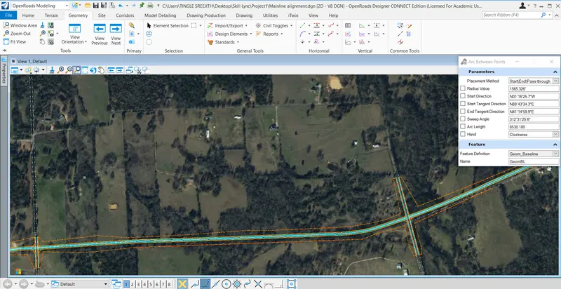
Now repeat the procedure for all road with intersection point. And go to arcs => Arc between elements => Draw new arc matching the alignment C/L.
Now use Horizontal=>offsets and tapers to create EOPs and EOS for the mainline alignments and intersections with appropriate FD. Use Draw arc between points command to draw the intersection junction radius.
Now turn on the aerial image and extend both lines till the intersection and check the angle difference between tangents, if its more than 1 degree provide curve to make it smooth. Also, after this we want to convert the lines into a complex line by complex by element method.
Results
Thus, the alignment and tie-in conditions for the intersection has been created
Q4. Design retaining wall alignment, top of wall and bottom of wall profile.
Aim & Introduction
A retaining wall is proposed where the proposed ROW is narrow or there is any steep slope existing on the sides. ORD has tools to design the retaining wall and the procedure for the same will be explained below.
Procedure
Open ORD=>Browse=>Q3mainline alignment.dgn=>file opens up with the earlier designed plan model as shown below.
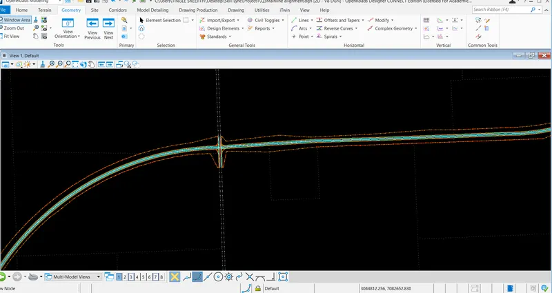
Go to the narrow ROW area => go to horizontal=> draw a line close to the ROW=>go to general tools=>standards=> select set feature definition=>select Alignment=>Road=>Geom_baseline_secondary.
Now go to Horizontal>modify=>start a station =>assign the station to the newly drawn line=>Now turn on the civil accudraw=>drop down menu=>click on E_switch dialogue mode=> the assigned stations can be seen.
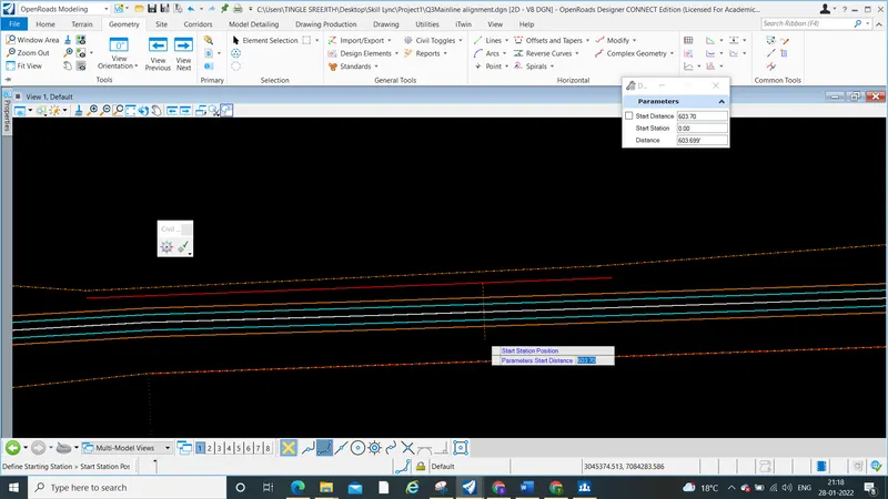
Now open the profile view for the drawn line=> Go to vertical and draw a complex by PI line with appropriate FD=> No click on the line =>flyout menu=> set the profile as active.
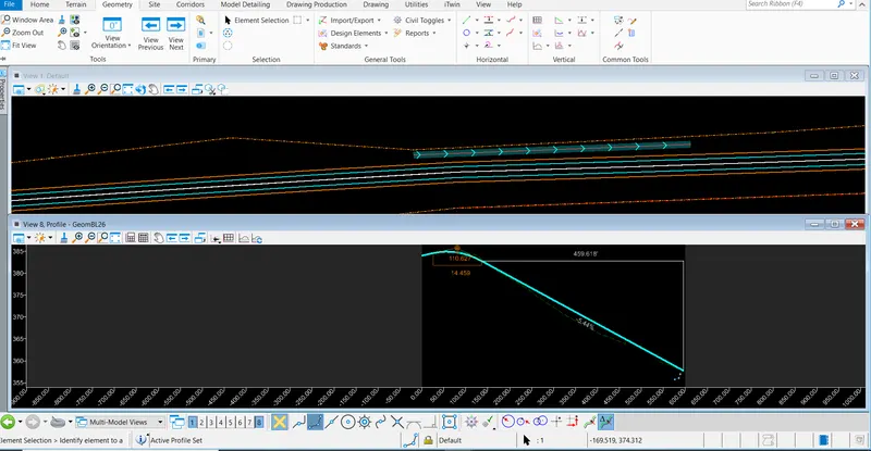
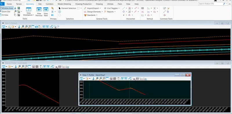
Now open the profile view for the road CL and it can be noted that Retaining wall alignment is located between ch:6200 and ch: 6800 in the mainline alignment as shown below.
Results
Thus, the profile line for the retaining wall has been created.
Q5. Design the parking lot peripheral alignment, design the proposed profile (partly in cut and fill).
Aim & Introduction.
Parking lot designs can be done with ORD and there many tools available in ORD to detail the parking lot as the end user requirements.
Procedure.
The procedure for designing the parking lots will be explained in detail below.
Open ORD=>browse file 'Q4 mainline alignment latest'=> go to Horizontal=> line between 2 points=>draw a rectangular parking block=>assign FD=>Linear =>site=>site parking.
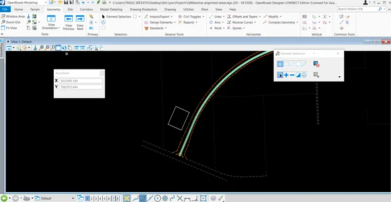
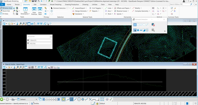
Now go to horizontal=>complex by geometry =>complex by elements and pick each line and make it complex=>Now go to element selection click on the line=>open profile view=>select the view to see the profile => go to vertical draw a profile line (ideally the parking should be a level surface, so go for a straight line).
Results.
Thus, the parking lot plan and profile has been created.
Q6. Export the alignments, profiles to Land XML and save it in geometry file.
The file has been saved to the project folder.