Project 1
Objective: Route the Wiring harness on Given Engine and Prepare flatten view drawing in CATIA V5.
Harness Design Criteria and Packaging Rules.
- Wiring harness should be routed in such a way that it is easy to assemble on vehicle. Wiring harness topology plays important role to meet this criteria.
- Wiring harness should be roued in such a way that it is easy to access for serviceability or failure analysis.
- Wiring harness routing shall provide ease in manufacturing accessibility easy removal and easy maintenance of attached equipments and wiring harness
- Routing through small structural holes and opening shall be avoided to minimize chaffing and handling of the wiring harness during installation.
- Provide additional slack to harness according to the surrounding and harness bending requirements.
- Providing drip loop whereerver necessary to avoid water ingress issues.
- Ensure the worst case envelope dimensions are considered for dynamic assemblies to meet the desired clearance requirement with wiring harness bundles.
- Avoid routing over the bolts near the bolted joints or screwed joints. IT may damage the harness.
- Harness should be routed at least 100mm away from ABC pedals.
- Enough clamps shall be provided to ensure that positive clearance with surrounding and safety of wiring harness. Distance between 2 clamps on the straight brach should be maximum 200mm.
- If the harness is routed between dynamic and stationery assemblies then ensure that fixed positive clamping is provided immediately at both end of assemblies. This is required to avoid harness damage in rocking conditions.
- Harness should be kept away from engine lifting hooks.
- Use of rubber grommets is recomended when passing from dry zone to wet zone. Telecopic grommets are recomended to use for the harness passing through clousers
- Ensure that harness branching is in line with the following requirements
Branch length should be minimum 50mm
Min. distance between clip and nearest branching point should be 25mm
Min. distance between two breakouts should be 50mm
Limit the number of brances from single branching point to 4.
Ensure that harness protection is provided according to surrounding temperature, manufacturability and expected reliability.
Engine Harness Design Procedure:
Define all the connectors and clamp and firtree on Electrical Part Design.
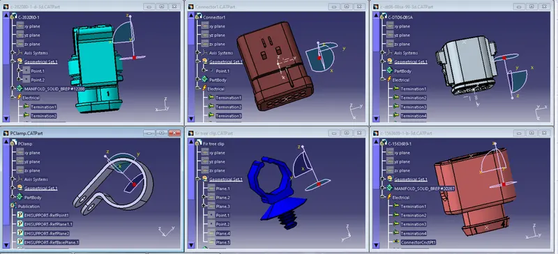
Position all the connectors, Clamps and Clips and Harness Channel is designed to mount on engine assembly and guide the harness.
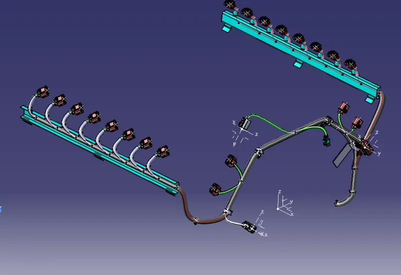
See belo images.
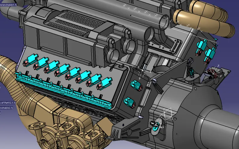
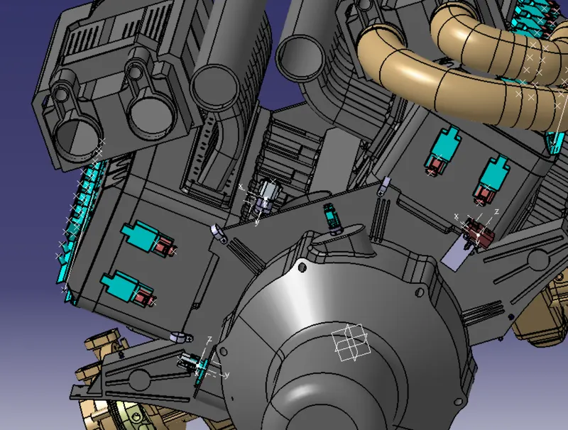
Routing the harness accrding to moutings clipping connection position.
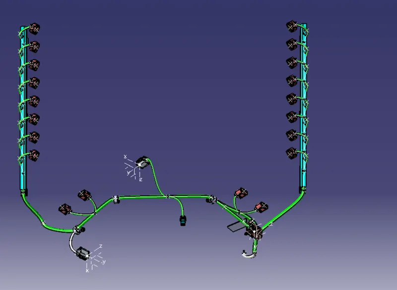
Defining the protective sleeve.
Checking the bundle connection segment.
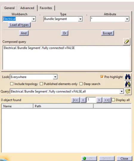
Conclusion: Conceptual routing is completed for given engine CAD data following all predefined design and packaging rules. Protective covering is provided.Contunitity check is performed. Facing issue in harness flatenning. It is not flatten completely only one multibranchable is getting flatten. Entire assembly is very slow and catia is crashing frequently.
Please see the attached CAD data.