Project 1
Procedure followed to route the wiring harness on V16 engine:
- Download the connector & clip 3D data from www.te.com
- Create the required geometrical parameters such as points and axis system
- Define parts as connectors from electrical part design workbench
- Define bundle connection point
- Define connector connection point
- Define clip & clamp as support part
- Define the channel as mouting equipment & define all bundle connection points
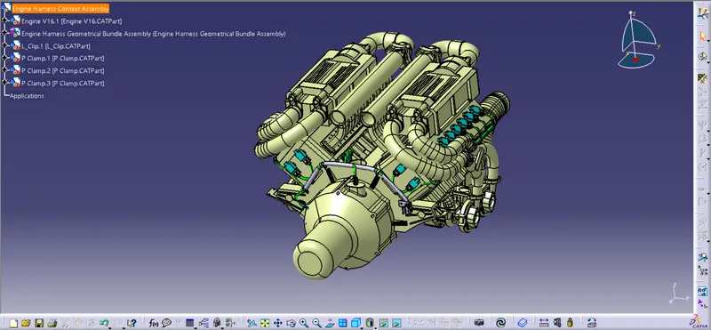
- Create new product as engine harness context assembly into that add another new product as engine harness geometrical bundle assembly
- Also add the V16 engine cat file into context assembly
- And save all in same folder
- Add all the connectors/clips/clamp & channel
- Position all the connectors/clips/clamp & channel in their desired location using manupulation/snap/smart move tools
- Place the p clamps and fir tree clips in exact position to ensure accurate routing of bundle
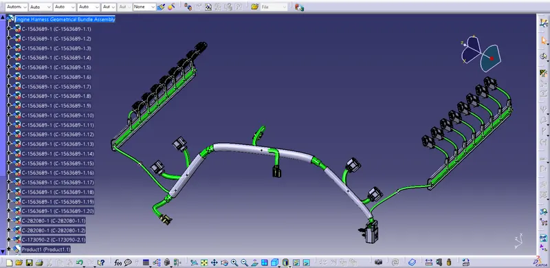
- Now in electrical harness assembly use geometrical bundle to convert in electrical
- In electrical harness installation use branch definition and route the wiring harness between connectors/clips/clamp & channels
- Use add branch point and split the harness
- Provide protective covering i.e. corrugated tubes from catalouge to the harness bundle wherever required
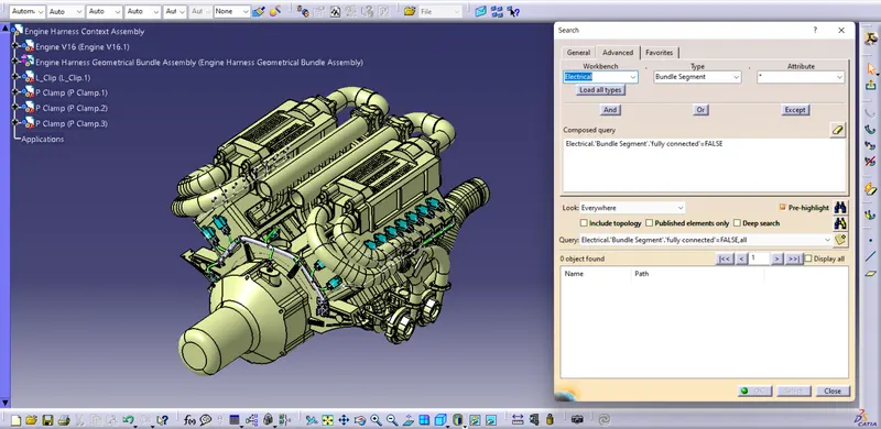
- Ensure the proper connectivity of bundle is maintained
- And save all
- Create new product and name it as flatten harness
- Go to electrical harness flattening workbench
- Click on harness flattening parameters and input all the parameters
- Extract the harness assembly product to flattening workbench
- Click on flatten command and select the plane to flatten the harness
- Rotate the branches if required
- Create new drawing file select A0 ISO sheet, potrait mode
- On the sheet select front view
- Change the properties and tick 3D wireframe is always visible
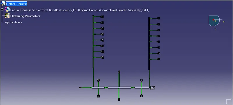
Harness Flatten View:
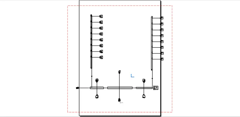
Harness Continuity Check: