Project 1
Report on Wiring Harness Engine:
Objective:
- Route the Wiring harness on Given Engine and Prepare flattened view drawing in CATIA V5. Application of all Packaging rules, Industry best practices studied in this course shall be demonstrated in design. Apply Protection coverings as required.
Electrical Components:
Connectors:
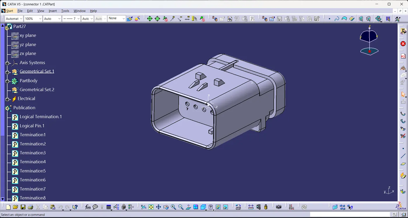
- c-282080-1-d-3d
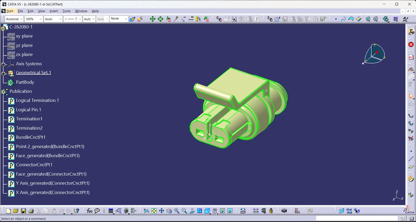
- c-1563689-1-b-3d
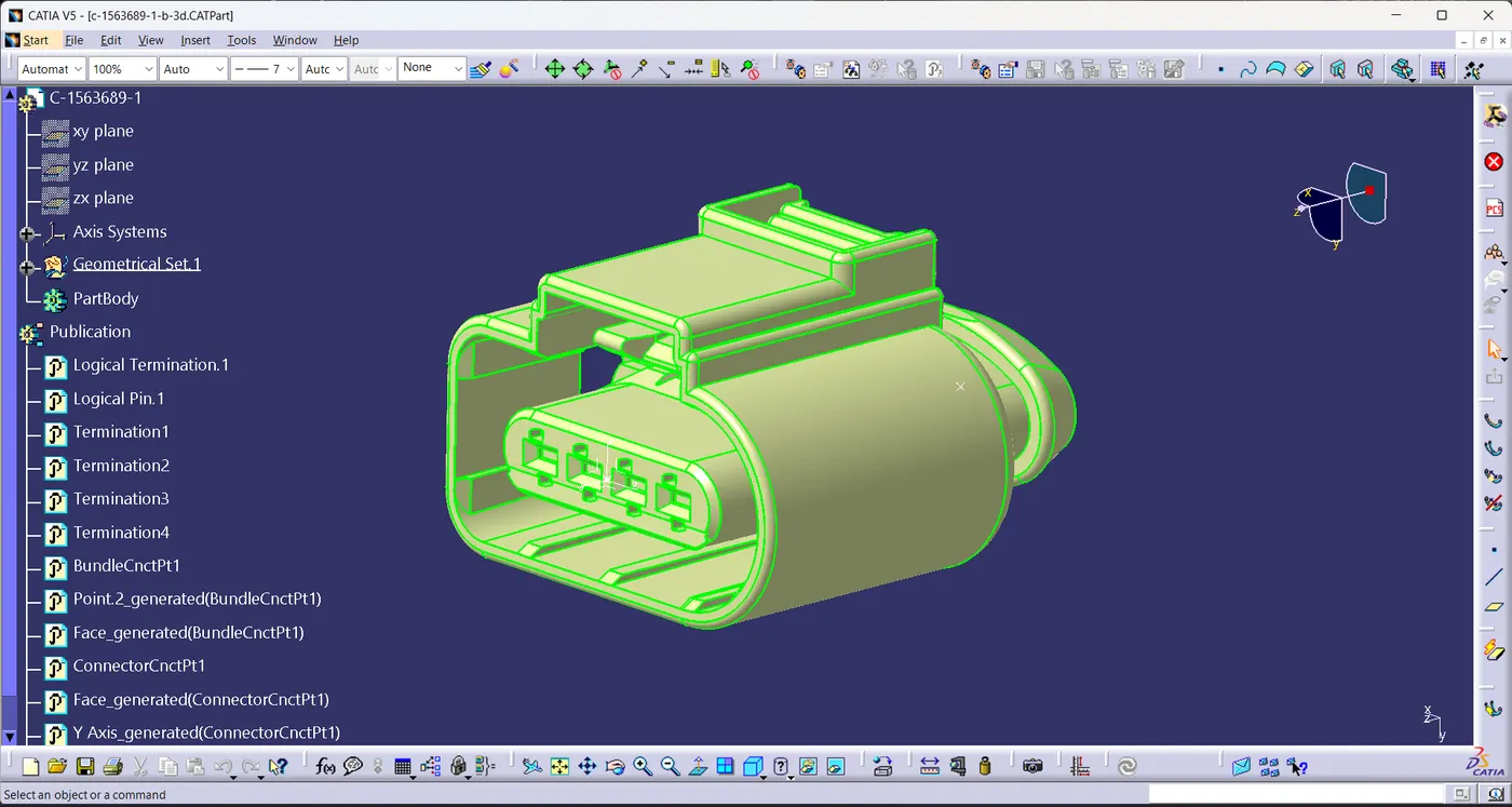
- c-776438-4-d-3d
Clips/Mountings:
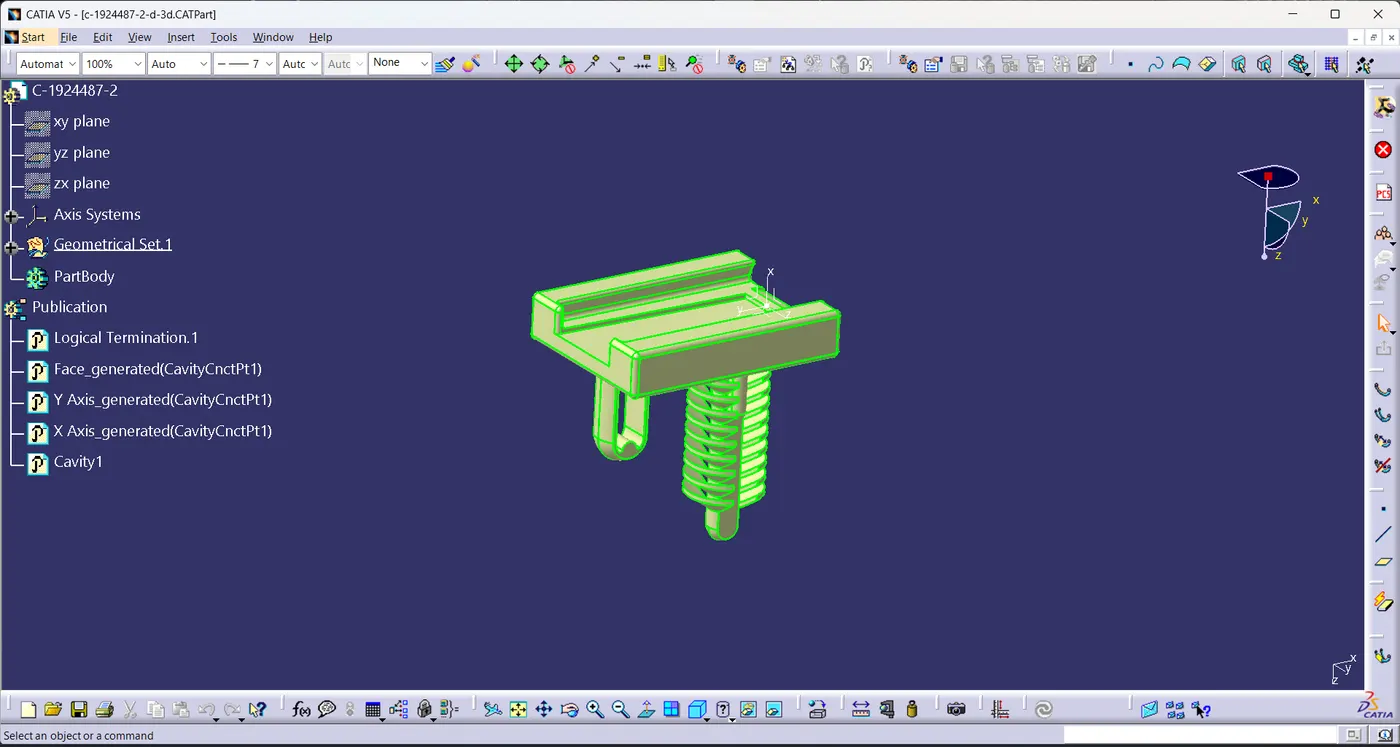
- c-1924487-2-d-3d
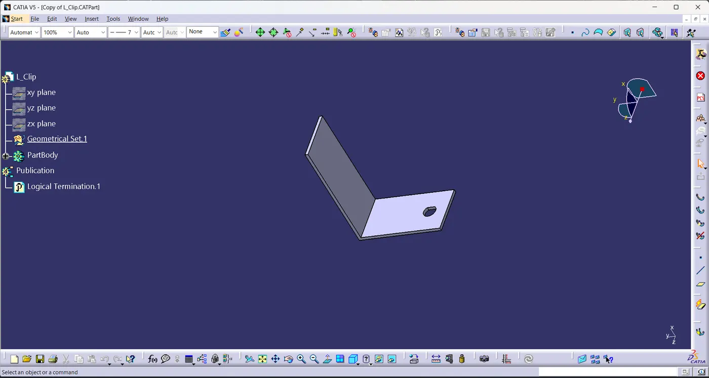
- L-Clip
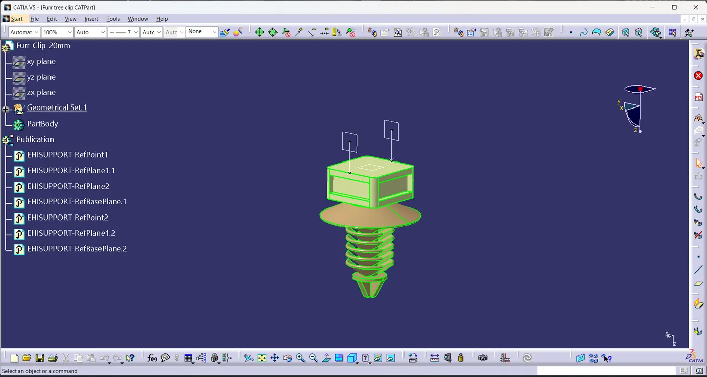
- Furr tree clip
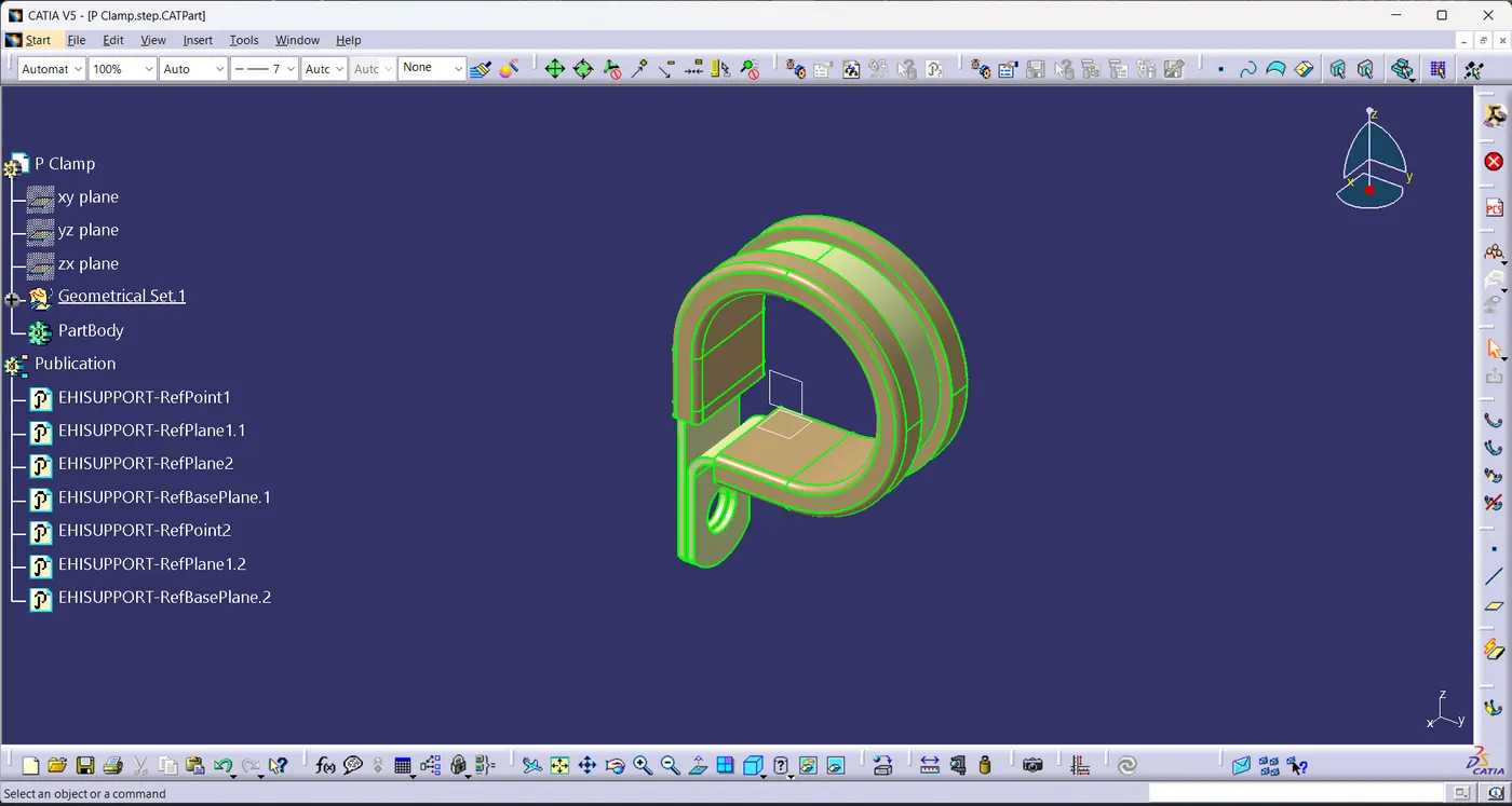
- P Clamp
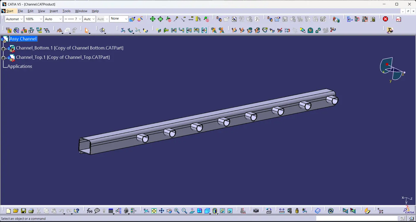
- Channel
Design Procedure:
- Get all the required 3D data and convert them into .CATPart files
- Define all the necessary electrical properties of connectors.
Connectors:
- The required geometrical parameters like point, axis on the mating face of the connector are defined.
- Then Define the Connector using define connector command in which we assign the no. of terminals and select the body.
- Define Bundle connection point by selecting representation and initial condition as the normal face and select the midpoint as point.
- Define Connector connection point by selecting mid-point as representation ,mating face ,Coincidence & orientation axis.
- Save the file and the connector is fully defined with all the necessary electrical properties.
c-282080-1-d-3d
c-1563689-1-b-3d
c-776438-4-d-3d
Clips/Mountings:
- The required Geometrical parameters such as Entry, Exit & Base plane is defined.
- Define the P clamp as support part using Define support command by selecting the entry plane as first plane ,entry plane origin as point, exit plane as second plane and base plane.
- Again define the p clamp using define support command by selecting the the exit plane as first plane, exit plane origin as point, second plane is pre-defined as exit plane by system and base plane.
c-1924487-2-d-3d
L-Clip
Furr tree clip
P Clamp
Channel
Engine:
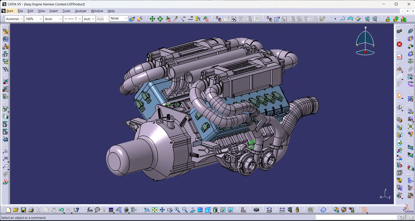
- Create a product file as Assy Engine Harness Geometrical Bundle and insert all the connector part file in it and arrange it .
- Engine Assembly is used as external reference for positioning the connectors.
- connectors and clips are arranged using the commands manipulation, compass/move, smart move in the assembly workbench.
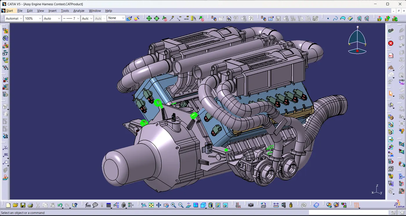
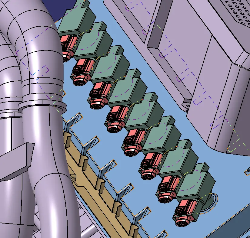
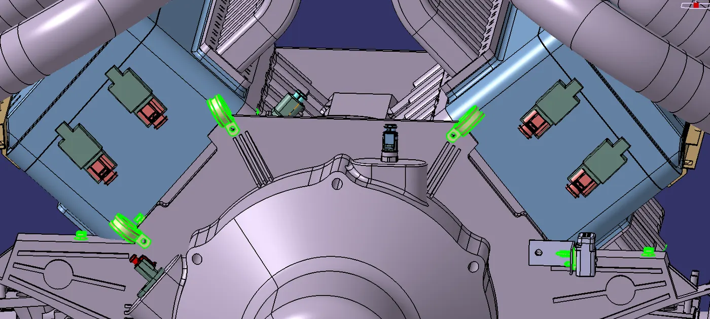
- Multi-branchable command is used to create main branches.
- Branch point command divides the branch to create the junction.
- And branch definition command used to create the sub branches.
Harness Assembly:
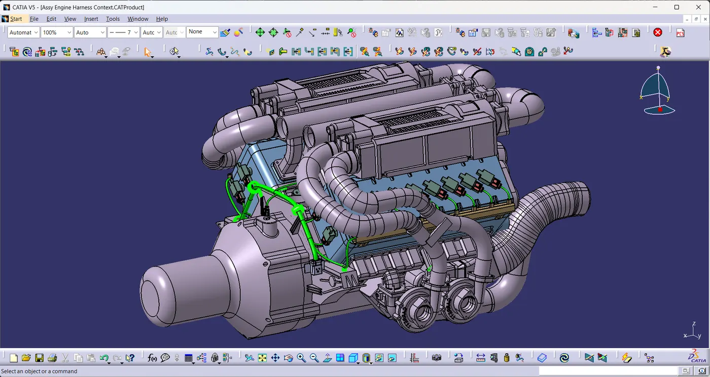 x
x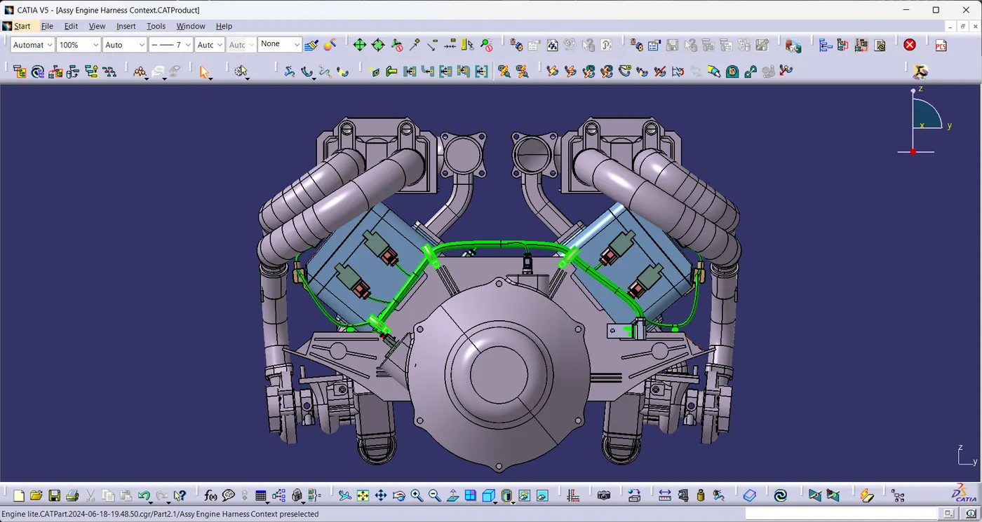
- Apply Protection coverings as required.
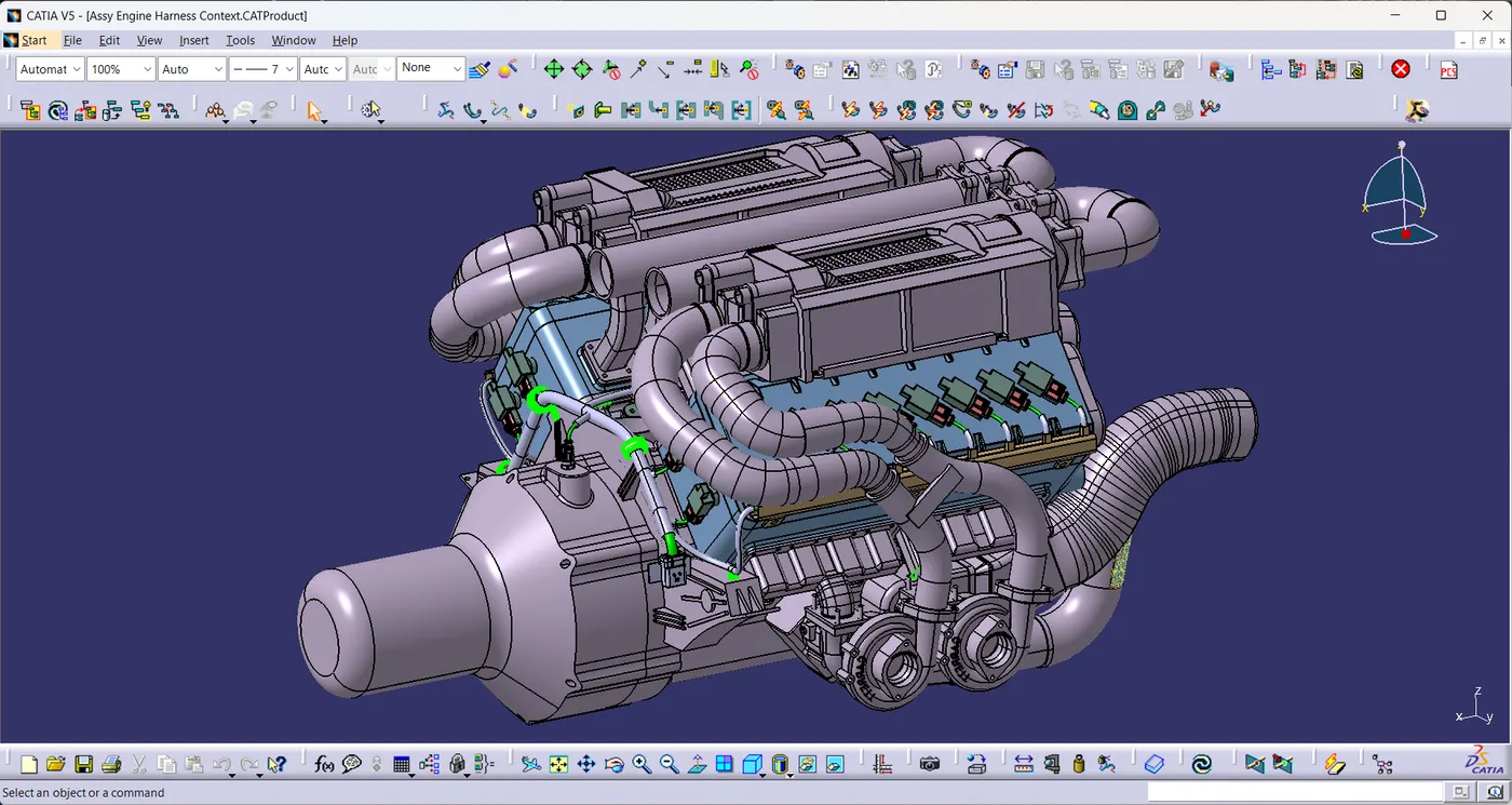
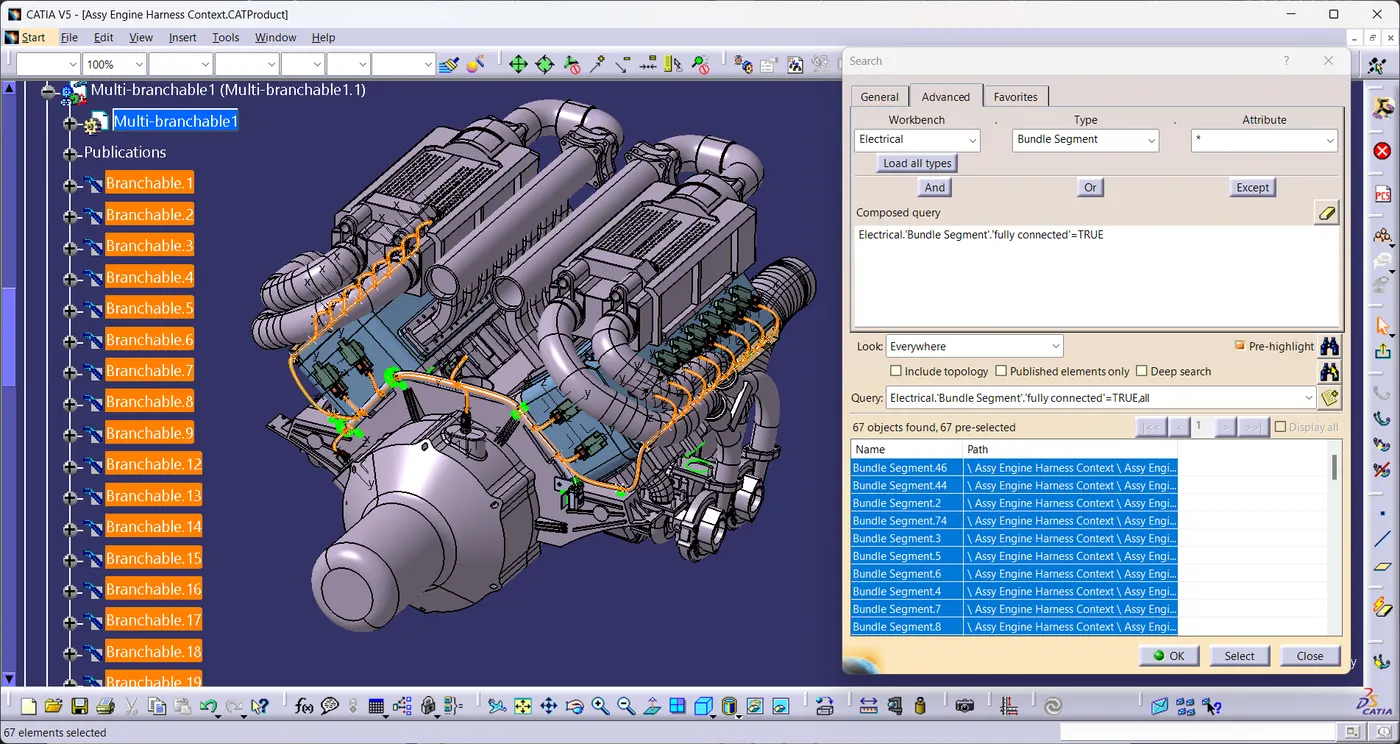
- Using Search command in the tools bar, the connectivity of the bundle of harness-A & B are checked.
- And all the Bundles are fully connected.
Flattened Assembly:
- Create a new product file and switch to electrical harness flattening.
- Activate the flatness parameters.
- Extract the harness model into the flatness assembly and flatten the bundles using flatten command.
- Adjust the Bundles position & orientation using manipulator, length, synchronise commands.
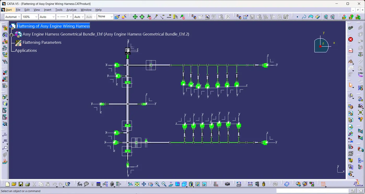
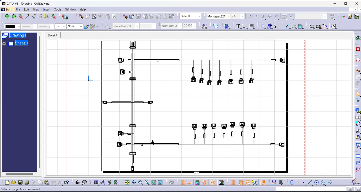
- After obtaining the flatten product convert the model into 2D drawing.
- Ensure bundles with protective coverings has different visuals on drawing view.
Drafting View Of Harness Assembly:
Conclusion:
- The Wiring harness on Given Engine is Routed and flattened view of drawing is prepared in CATIA V5. Application of all Packaging rules, Industry best practices studied in this course are demonstrated in the design. Protection coverings are applied as required.
As the size zip file is more than 20MB, The file is unable to upload.
The google drive link for Zip file of Engine Wiring Harness, Flattened view of Engine wiring harness file and Drawing file of flattened view is :
https://drive.google.com/file/d/15qRSdXdrRJLhW_vaT6mNsQ5YeLvyr3a9/view?usp=sharing