Project 1
Solution:
Simulink Model:
Blocks Used:
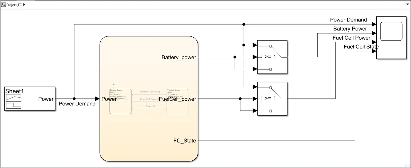
- Signal Builder - used as an input to provide the power demand data. The power demand at different time interval is entered as the input.
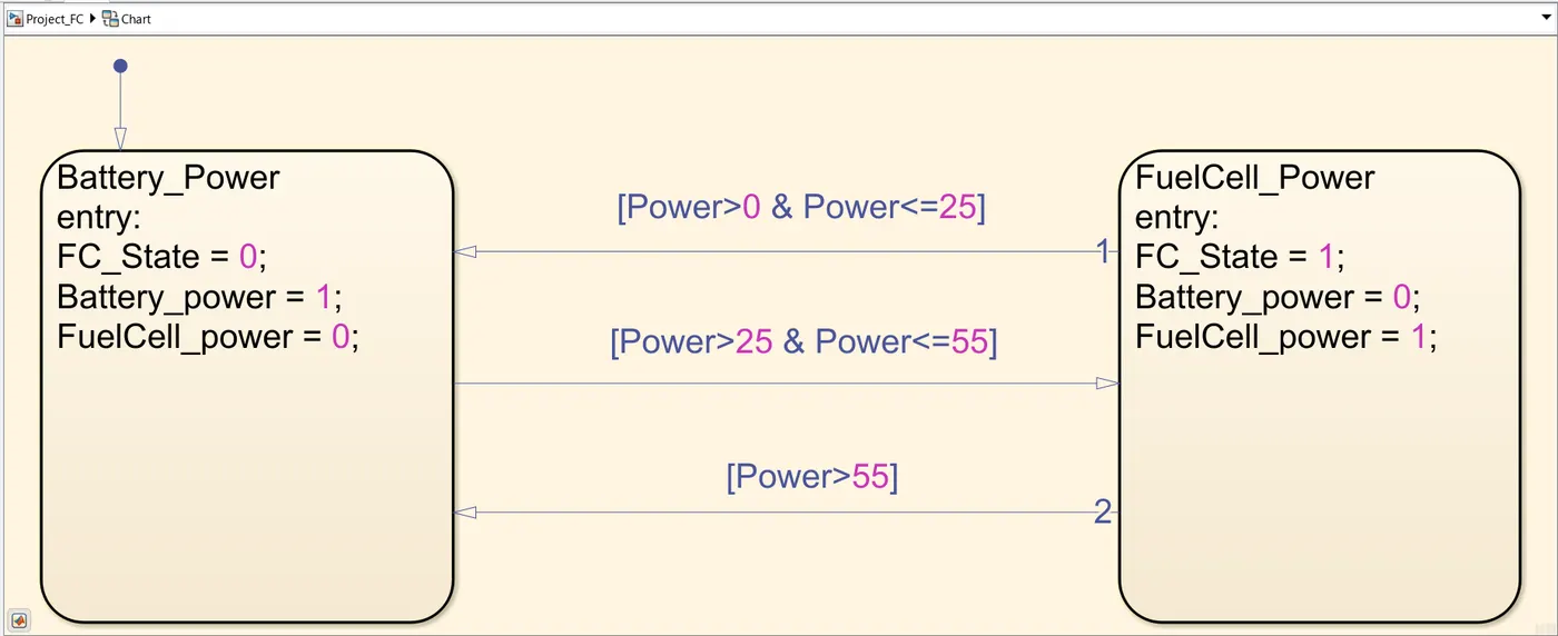
- Stateflow Chart - used to create the given flow chart. It consists of two states, Batter_Power and FuelCell_Power.
- Switch Block - used to pass input 1 (power demand), when the condition in input 2 is satisfied, else it passes input 3 (0).
- Scope - used to display simulation result.
Working:
- The input values of Power Demand is updated in the signal builder block and this signal is given as the input to the stateflow block.
- Inside the stateflow chart, there are two states, Batter_Power and FuelCell_Power which will be selected based on the conditions given tin the flow chart. The operating range of fuel cell and battery is selected as below:
Fuel Cell Operating value - 26kW to 55kW, Battery Operating value - 0kW to 25kW and power demand greater than 55kW.
- The given condition for the transition of power supply between fuel cell and battery is, When the power demand is less than minimum fuel cell power (<26kW), The fuel cell is put on stand by and battery is used to supply power demand. When the power demand is greater than the minimum fuel cell power (>=26kW), Fuel cell is used till the power demand is within maximum Fuel cell power (<+55kW), if the power demand exceeds the maximum Fuel cell power (>55kW), Battery is used to provide the required power.
- This logic is implemented inside the stateflow chart and the states are transitioned based on the above conditions. When the Battery_power state is active, Battery power is set to 1 and fuel cell operating state and the Fuel Cell power is set to 0. When the FuelCell_power state is active, Battery power is set to 0 and fuel cell operating state and the Fuel Cell power is set to 1.
- Battery power, Fuel cell power and Fuel cell state are the output from stateflow chart. Switch block is used to make the selection of output signal based on the Battery poer and Fuel cell power signals.
- If the output battery power signal is 1, then the power demand is given as the output of switch block, else 0 is passed as the output.
- Similarly, if the output fuel cell power signal is 1, then the power demand is given as the output of switch block, else 0 is passed as the output.
- The power demand, output from both switch block and the Fuel cell state is given into scope to visualize the result.
Result Screenshot:
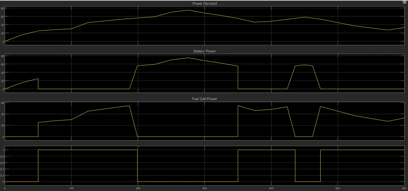
The input Power Demand and the outputs Battery Power, Fuel Cell Power and the Fuel Cell Operating State is displayed on the scope. When the power demand is within the operating range of fuel cell (26kW to 55 kW), the power required is provided by the fuel cell and the fuel cell operating state is ON (1). When the power demand falls below the minimum value (25kW) or exceeds the maximum value (55kW) the fuel cell operating state is OFF (0), and the the power required is provided by the battery.