Project 1
Answer:
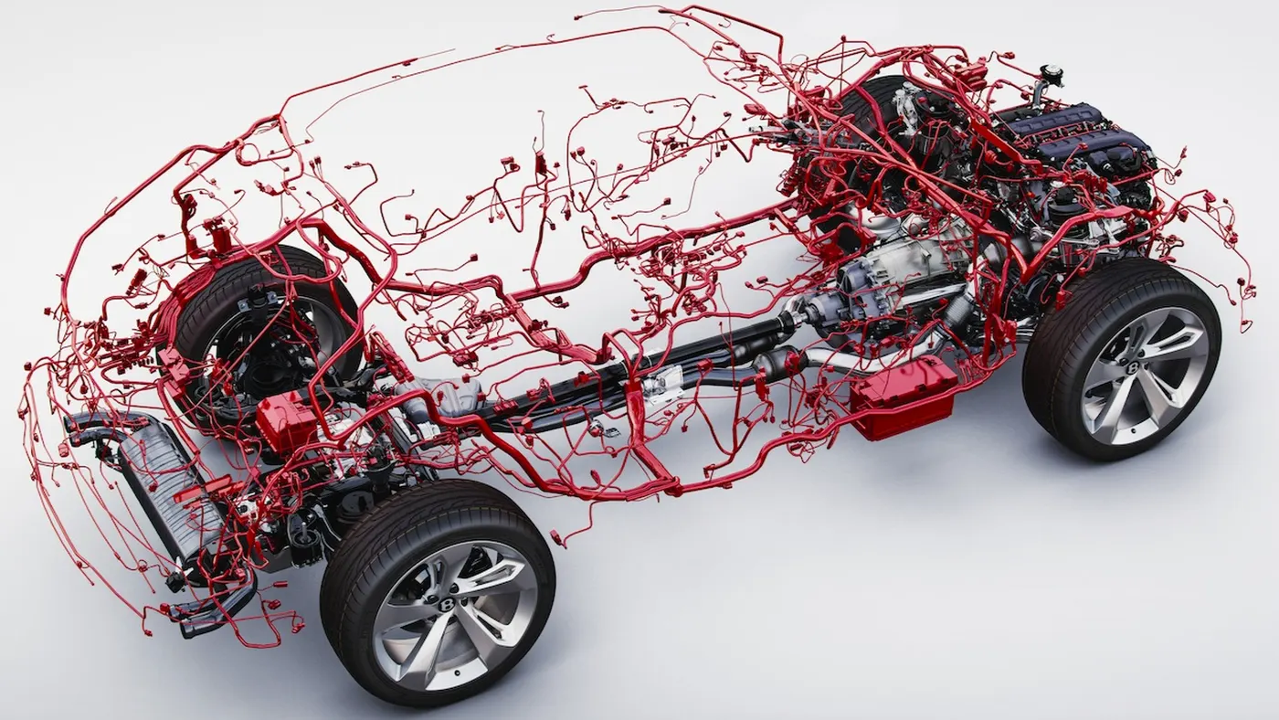
An automotive wiring harness is a bundle of wires, connectors, and other components that are used to transmit electrical power and signals within a vehicle. It serves as the nervous system of the vehicle, connecting various electrical components such as sensors, switches, lights, and other electronic devices to the vehicle's power source (typically the battery) and to each other.
key aspects of automotive wiring harnesses:
Materials: Wiring harnesses are typically made from copper wires, which offer good conductivity and flexibility. These wires are often insulated with materials such as PVC, cross-linked polyethylene, or Teflon to protect them from moisture, heat, and abrasion.
Connectors: Wiring harnesses feature connectors at various points to facilitate easy installation, maintenance, and repair. These connectors may include terminals, plugs, sockets, and junction boxes, which allow different components to be easily connected and disconnected.
Organization: Wiring harnesses are carefully organized and bundled together to minimize clutter and ensure efficient routing of wires throughout the vehicle. They are often designed to fit specific vehicle models and configurations, with lengths and routing optimized for each application.
Protection: Wiring harnesses are designed to withstand the harsh conditions within a vehicle, including temperature fluctuations, vibrations, and exposure to moisture, chemicals, and debris. Protective features such as abrasion-resistant sheathing and moisture-resistant seals are often incorporated to enhance durability and reliability.
Functionality: Wiring harnesses play a crucial role in ensuring the proper functioning of various electrical systems within the vehicle, including the ignition system, lighting, engine management, entertainment, communication, and safety systems. They help to ensure consistent power delivery and signal transmission, thereby contributing to overall vehicle performance and safety.
Connectors,Clips, Clamps & Supporting channels:
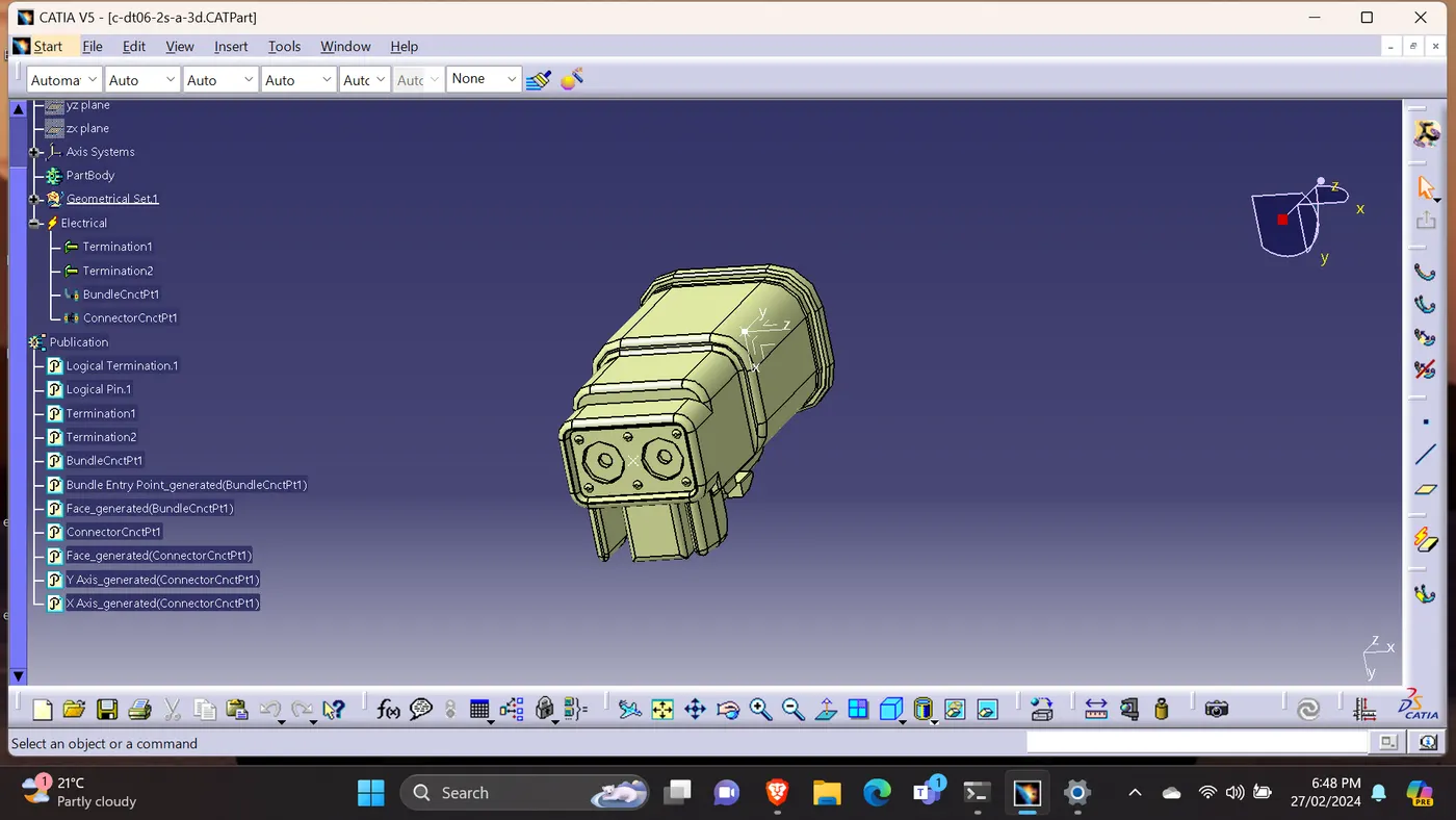
2 Pole Connector:
1)Downloaded the engine CAD part from the given question.
2)converted to CATProduct.
3)Used the required connectors to build the wiring harness.
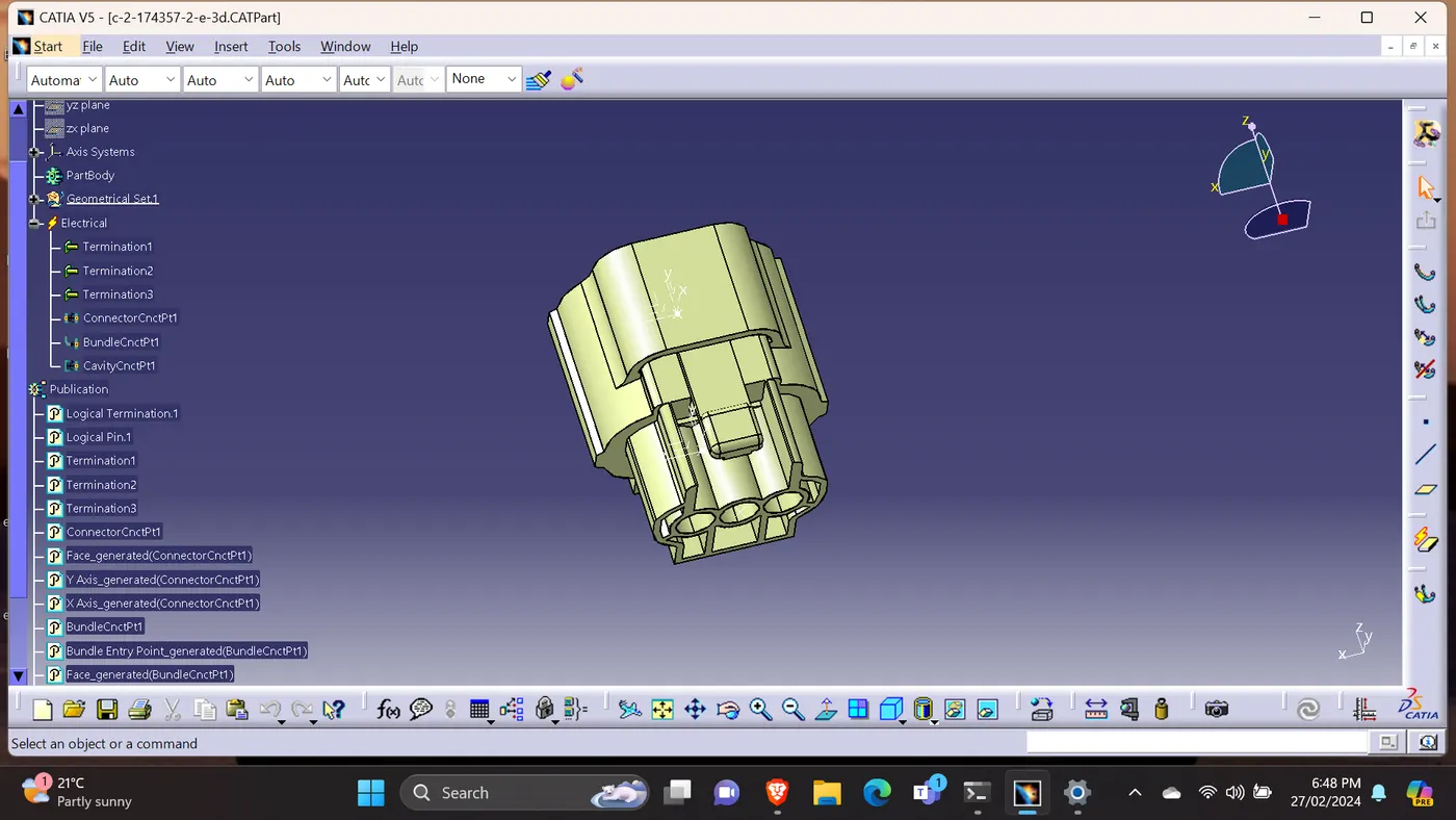
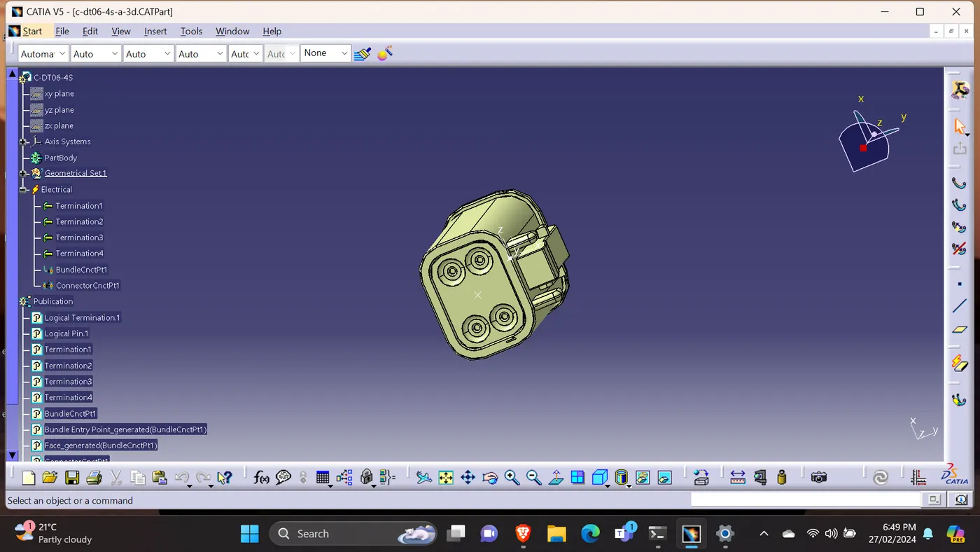
4)Created the required geometrical parameters. Defined the bundle entry point, connector connection point & cavity connection point.
5)Defined the connector part as electrical.
6)Used the 2 pole, 3 pole, 4 pole connectors.
7) Used the the CATIA manipulation, compass, snap & smart move commands to fix the connectors and the required parts at their appropriate places.
3 Pole Connector:
4 Pole Connector:
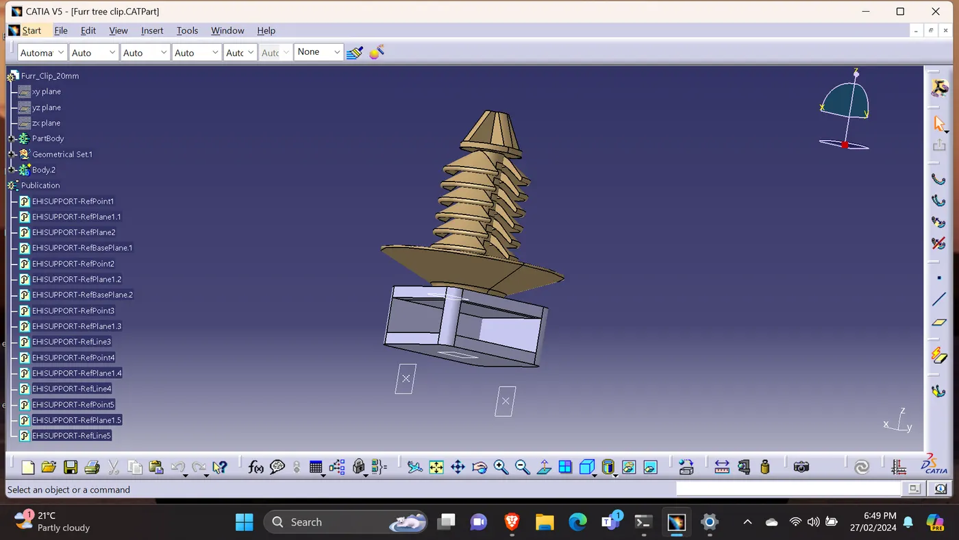
Furr Tree Clip:
1)Used the required Clips(Furr tree) to build the wiring harness.
2)Created the required geometrical parameters. Defined the bundle entry point.
3)Defined the furr tree clip part as electrical.
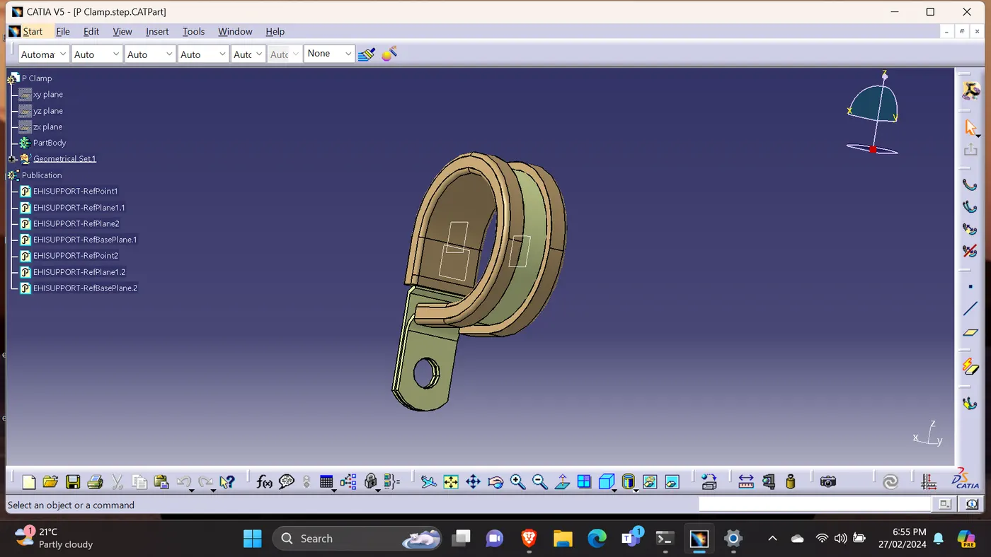
P Clamp:
1)Used the required Clamps(P Clamp) to build the wiring harness.
2)Created the required geometrical parameters. Defined the bundle entry point.
3)Defined the CAT part as electrical.
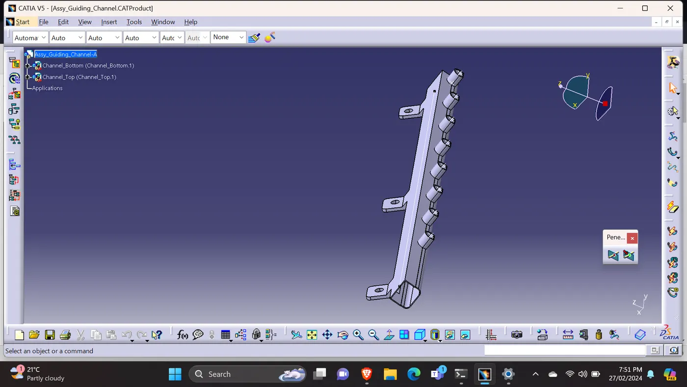
Supporting channel:
1)Used the given supporting channel to protect the wiring harness.
2)Created the external reference to connect the bundle to the each connector connected to the each coils.
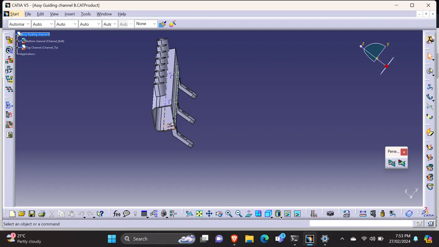
Supporting Channel-Symmetry:
1) Used the symmetry function command to get the supporting channel for another side.
2)Used the external reference line to connect the bundle.
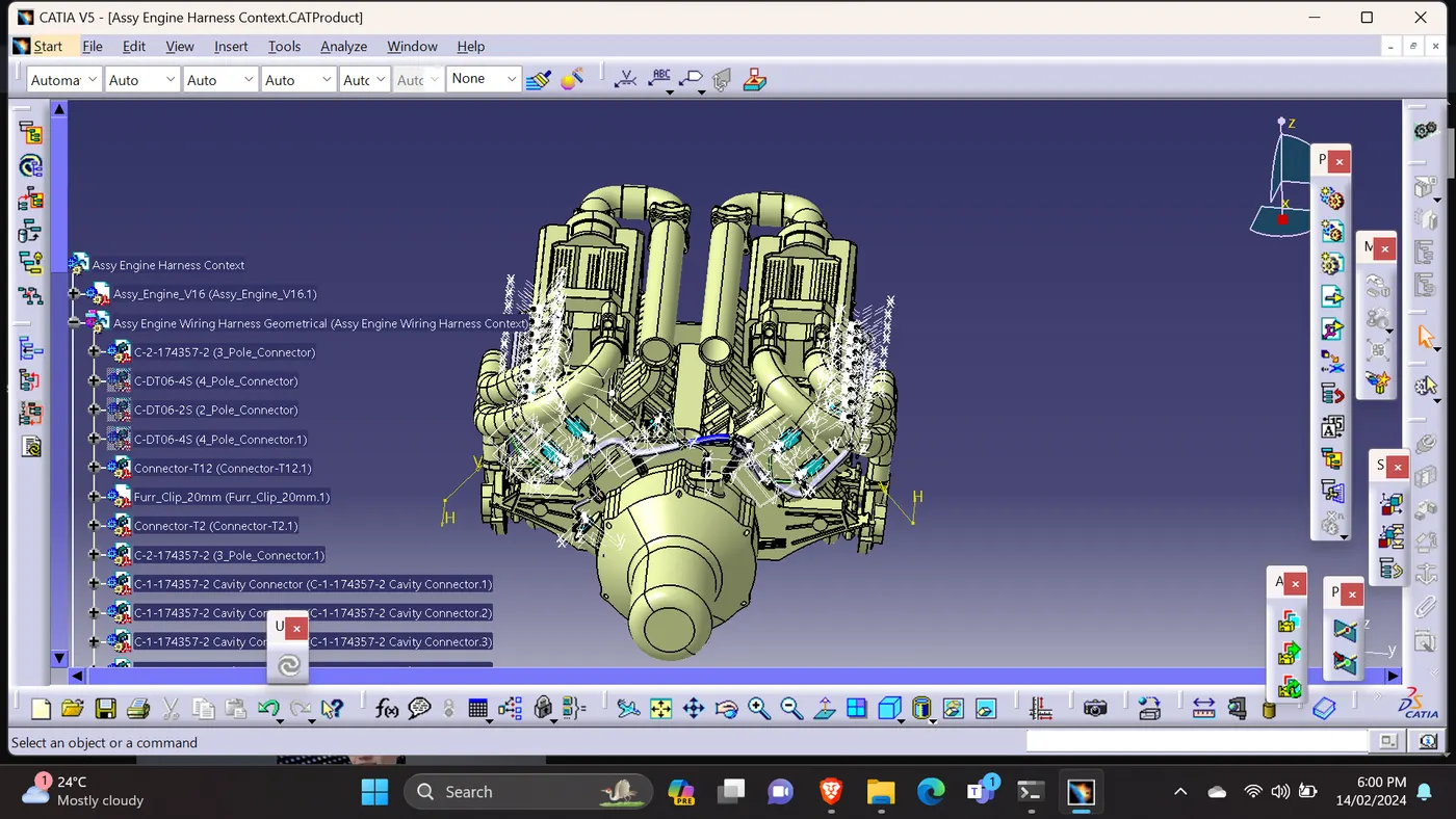
Engine Assy Context:
1)Downloaded the engine CAD part from the given question.
2)opened that in CATIA.
3)Opened the Product file to keep the engine file, wiring harness file & the required the parts.
4)Used the corrugated tubes to protect the wiring harness.
5)Checked the continiunity & flattened the wiring harness assy.
6)Used the drawing sheet.
Continunity check resut:
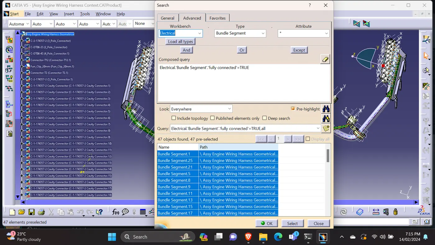
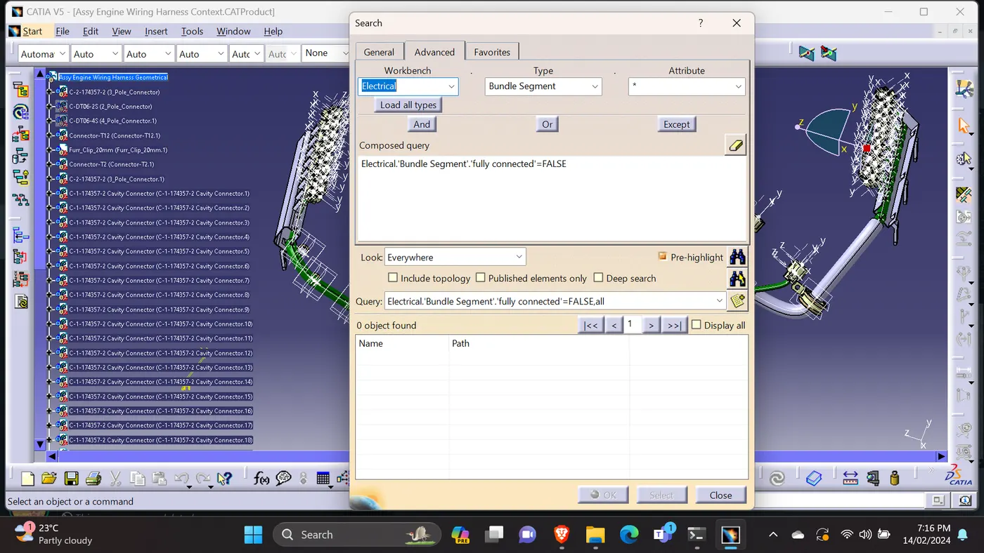
1)Once done the wiring harness assy routing, checked the continunity for the bundle.
2)Moved to assembly design workbench, went to edit, search.
3)As per the below picture table will pop-up table.
4)selected the electrical workbench, selected the bundle segment type and fully connected attribute.
5)selected the 'TRUE' & 'FALSE' option to find the continunity of the bundle.
6)Attached the screenshot.
Assy Wiring Harness file:
1)opened the wiring harness assy in a seperate window to do the flattening.
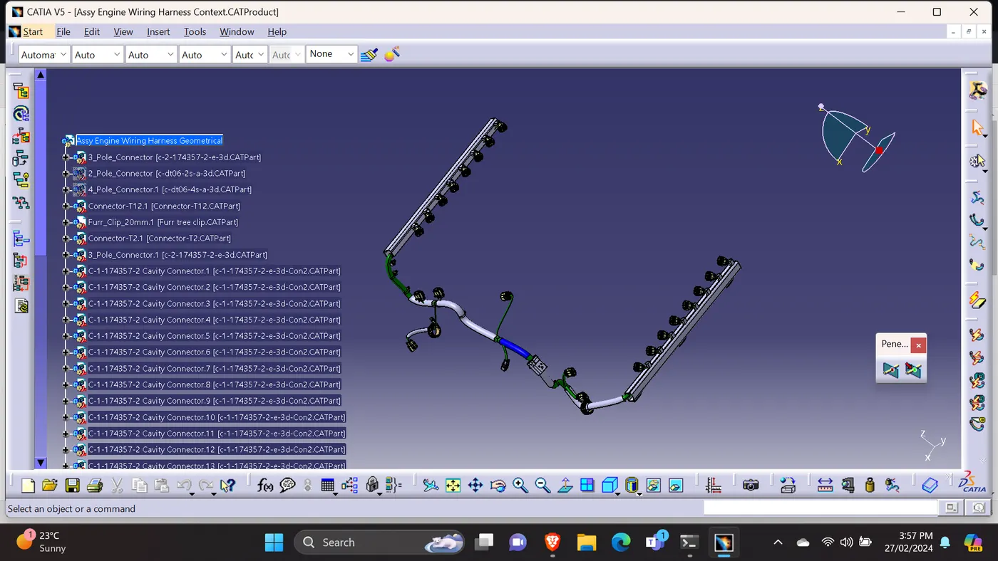
Assy Wiring Hraness Flatten Drawing:
1)Opened flatten product to flatten the wiring harness file.
2)defined the all flattened parameters.
3)flattened the wiring harness.
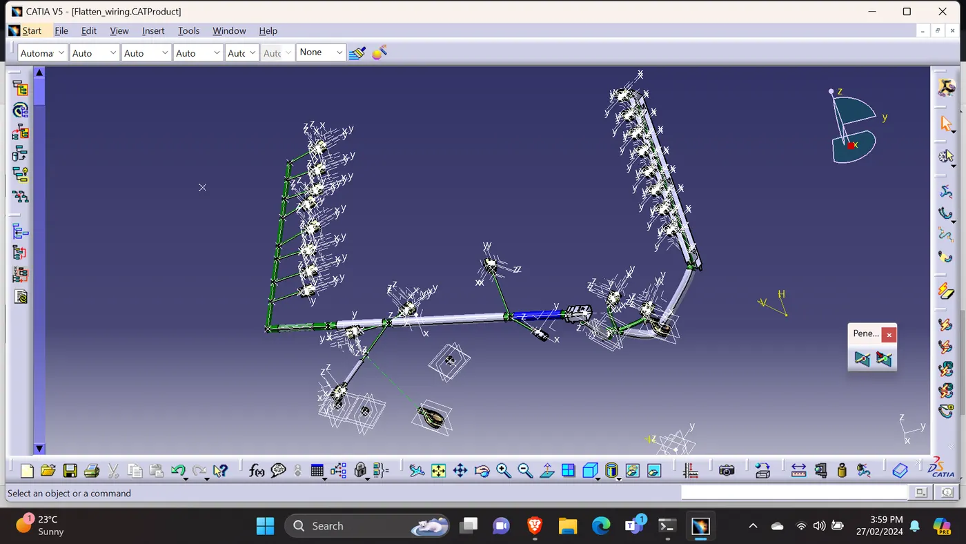
DrawingSheet:
To generate a drawing view of the harness, opened a new drawing file, selected the command 'front view', then go the flattened harness window and selected an appropriate face.
Right clicked the drawing sheet and selected the properties.
In the view tab, '3D wireframe' and 'Always visible' in the dress up settings to make the bundle segments visible.
T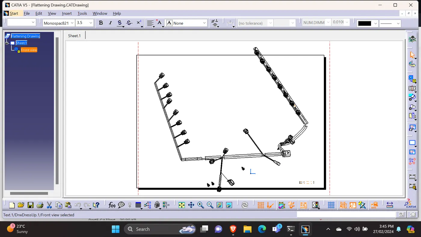
1)Attached all the required files (CAT Part).
2)Attached all the required screenshots & images for the reference.
3) ( https://drive.google.com/drive/folders/1bjFuW_JKPJP6lXUl0vTVyKxYLDDn4Jea?usp=drive_link )
Uploaded all the files in the goolge drive & attached the google drive link. Kindly find the attachments.