Project 1
PROJECT-1
Design a multi-storey Residential Building located in Bangalore using STAAD Pro Connect Edition. The specification must be as follows:
Building floors – G + 6 + R
Plan dimension – B = 25m, L = 16m
Storey Height – h = 3.5m
Soil – Hard soil
Use - Residential Purpose
Safe Bearing Capacity – 180kN/m2
Maximum slab thickness – 150mm
Assume suitable sections for structural elements. Follow IS456, IS1893 and IS875.
1. Prepare a Design Basis Report for the project.
2. Create structural model using STAAD Pro Connect Edition.
3. Prepare DL, LL, WL and EQL load calculations as per IS 875 standards.
4. Design slab element using MS-Excel.
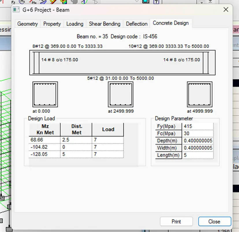
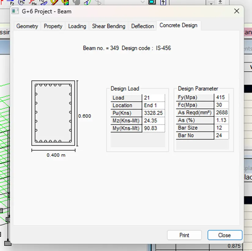
5. Design beam and column element using STAAD RCDC. Attach the design calculation report.
6. Design Foundations using STAAD Foundation.
7. Prepare bar bending schedule for beam and column using STAAD RCDC.
8. Attach necessary sketches and drawings wherever required.
9. All stipulations, assumptions and design parameter must adhere to Indian Standards.
Aim: To design a multi-storey Residential Building located in Bangalore using STAAD Pro.
Introduction:
This project involves analysis and design of reinforced concrete framed structure of multi-storied (G+6) residential building located in Bangalore using analysis and design software STAAD Pro as per Indian standard code of practice.
Basic details of the structure:
Utility of building - Residential building
Number of stories – 6
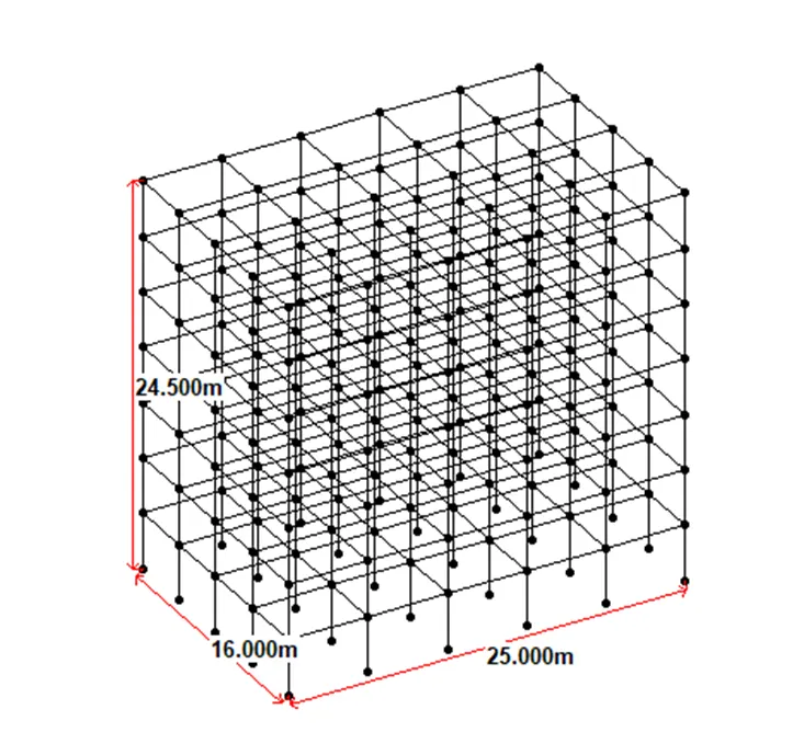
Plan dimension – 25mx16m
Storey height – 3.5m
Soil type – Hard
Safe bearing capacity – 180kN/m2
Maximum slab thickness – 150mm
Assuming, Concrete grade – M30
Steel grade – Fe415
Column size – 0.6 x 0.4 m
Beam size – 0.4 x 0.4 m
Loads – DL, LL, EQL, WL
Type of construction – RCC Framed Structure
Procedure:
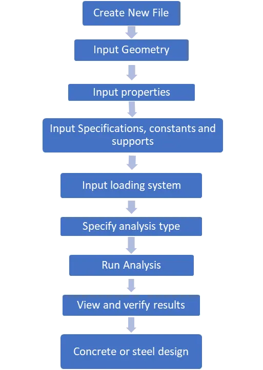
Step1: Creating New File
Start STAAD Pro by double clicking on the icon.
Click New project, tick space option, give file name, choose location, and change the units to meter and kilo newton. Click next.
Tick on Add beam and click on finish.
Step2: Generating the model geometry
Go to Geometry tab and select run structure wizard.
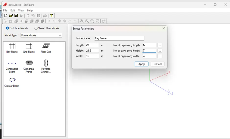
Select frame model and choose bay frame.
Input length, height, width and number of bays. Click on apply.
Now, transfer the model.
Adding slab section (plate element) to the model:
Open front view. Select ‘Cut Section’ command.

Choose ‘Select to View’ option. Click on ok.
Select the view of the storey by dragging.
Open isometric view.
Select ‘Add 4-Noded Plates’ option.
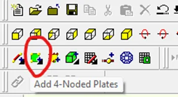
Select the four nodes to add plate.
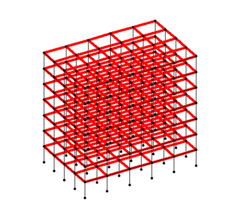
Select the Plates Cursor, and select the plates created in the model.
Go to Geometry tab and select ‘Translational Repeat’ option.
Select Z direction, add number of steps (3), default step spacing (4) and click on ok.
Select ‘Display whole structure’ command.
Now, select all the plates of the storey.
Go to Geometry tab and select ‘Translational Repeat’ option.
Select Y direction, add number of steps (6), default step spacing (3.5) and click on ok.
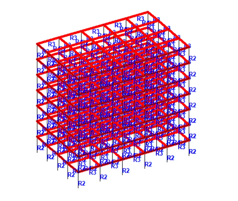
Step3: Specifying member properties
From the file menu go to commands tab.
Go to member property, select prismatic and choose rectangle.
Input width and depth values.
Click on add and close.
Click on ‘Thickness’ option.
Input the value, click on add and close.
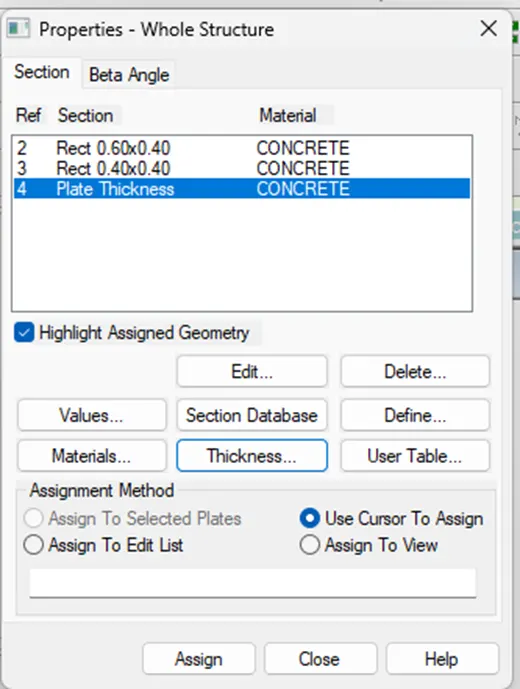
Select the section 2 in property page, go to ‘Select’ tab and choose Beams parallel to Y.
Choose ‘Assign To Selected Beams’, click on Assign and Yes.
Select the section 3 in property page, go to ‘Select’ tab and choose Beams parallel to X & Z.
Choose ‘Assign To Selected Beams’, click on Assign and Yes.
Select the section 4 in property page. Choose ‘Assign To View’, click on Assign, Yes and Close.
Step4: Specifying supports
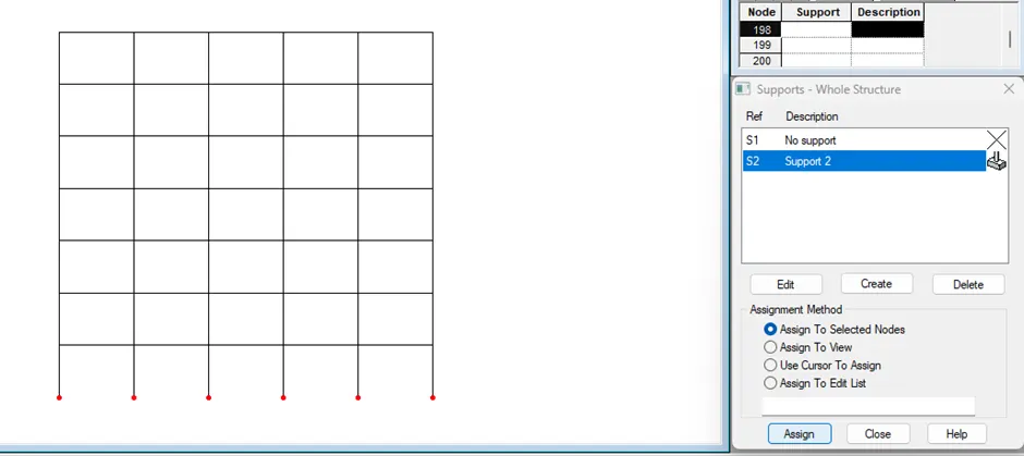
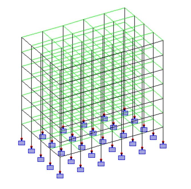
Go to commands, select support specifications, select fixed and click on add.
Select the support, open front view, select all the nodes at the base.
Choose ‘Assign To Selected Nodes’, click on Assign, Yes and Close.
Step5: Specifying loads
Go to Load & Definition tab.
Go to ‘Definitions’ and select ‘Seismic Definitions’.
Click on Add option. Choose the Code (INndian:IS1893-2002/2005), and click on generate.
Input the required seismic parameters.
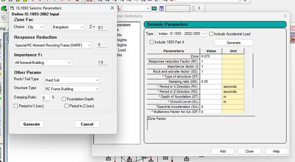
Click on Generate option. Click on Add.
Input SelfWeight Factor 1 and click on Add.
Select ‘Member Weights’ from Seismic Definition.
Choose loading type (UNI). Input Weight value.
[27.85({0.23*20*3.5} + {0.125*20*3.5} + {0.125*20*1.2})]
Click on Add option.
Select ‘Floor Weights’ from Seismic Definition.
Input Pressure value (2), Y Range minimum (3.5) and maximum (24.5).
Click on Add and Close.
Select the Uniform Load from Seismic Definitions, go to ‘Select’ tab and choose beam parallel to X and Z.
Select ‘Assign To Selected Beams’, Click on Assign and Yes.
Go to Definitions and select ‘Wind Definitions’.
Click on Add option. Select Type 1, Wind 1, click on Add and Close.
Select Type 1, Wind 1 from Wind Definitions and click on Add.
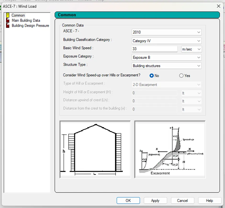
Choose ‘Calculate as per ASCE-7’ option.
Input the parameters in Common data and click on Apply.
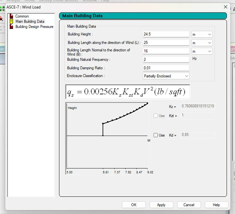
Go to ‘Main Building Data’, input the values and click on Apply.
Go to Building Design Pressure, choose windward pressure, click on Apply and Ok.
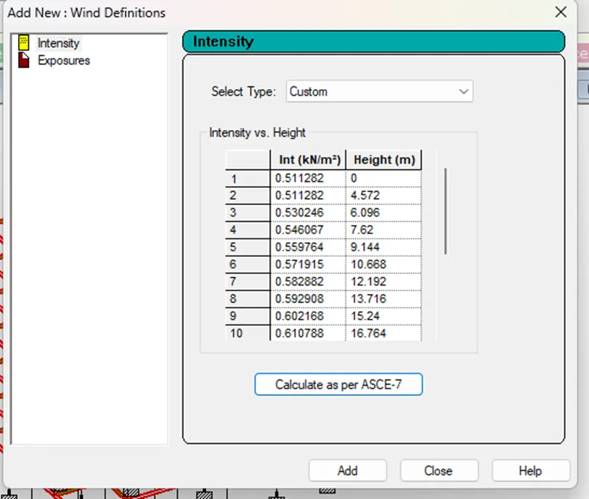
Now click on Add.
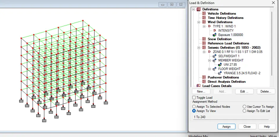
Enter Exposure factor 1, click on Add and Close.
Select exposure from Wind Definitions, choose ‘Assign To View’, click on Assign and Yes.
Defining Load Cases:
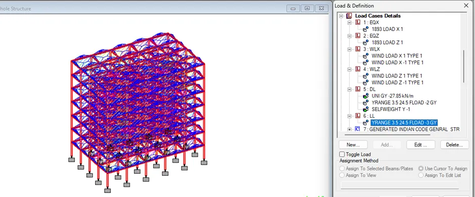
Select Load Case Details and click on Add.
Select loading type-Seismic, give title ‘EQX’ and click on Add.
Select loading type-Seismic, give title ‘EQZ’ and click on Add.
Select loading type-Wind, give title ‘WLX’ and click on Add.
Select loading type-Wind, give title ‘WLZ’ and click on Add.
Select loading type-Dead, give title ‘DL’ and click on Add.
Select loading type-Live, give title ‘LL’, click on Add and Close.
Select EQX from Load Case Details, click on Add.
Choose seismic loads from load items, select X direction and factor 1, click on Add and Close.
Select EQZ from Load Case Details, click on Add.
Choose seismic loads from load items, select Z direction and factor 1, click on Add and Close.
Select WLX from Load Case Details, click on Add.
Choose Wind loads from load items, select X direction and enter factor as 1, click on Add. Enter factor -1, click on Add and Close.
Select WLZ from Load Case Details, click on Add.
Choose Wind loads from load items, select Z direction and enter factor as 1, click on Add. Enter factor -1, click on Add and Close.
Select DL from Load Case Details, click on Add.
Select selfweight, enter factor as -1 and click on Add.
Select member load, choose uniform force, input force -27.85 and click on Add.
Select Floor load, enter pressure value -2, define Y Range minimum 3.5 maximum 24.5, click on Add and Close.
Select selfweight from DL in load case details, choose ‘Assign To View’, click on Yes and Close.
Select uniform force from DL in load case details, select beams parallel to X and Z, choose ‘Assign to selected beams’, click on Assign, Yes and Close.
Select LL from Load Case Details, click on Add.
Select Floor load from load items.
Input pressure value -3, Y Range minimum 3.5, and maximum 24.5.
Click on Add and close.
Click on load case details, select add option.
Choose autoload combination option. Select load combination code (Indian). Click on generate loads, add and close.
Step6: Specify analysis type
Go to commands, select analysis and click on perform analysis.
Choose no print, and click on ok.
Step7: Analysis
Go to analyze tab and select Run Analysis.
Choose view output file if there are any errors and click on done.
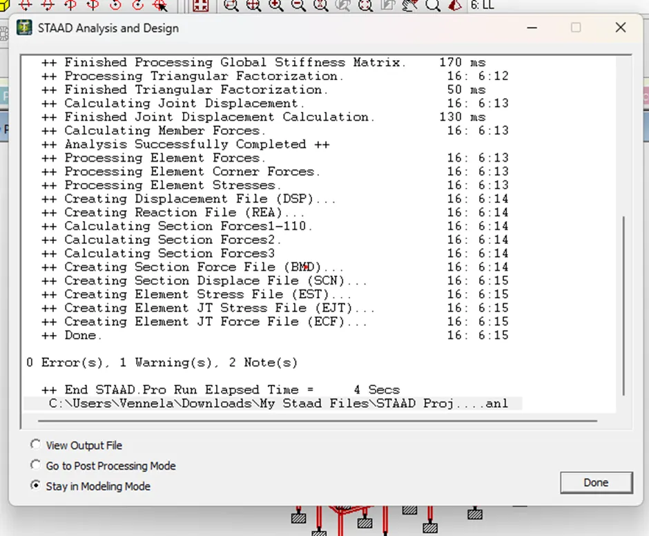
Click on post processing mode and click on Done.
Now click on apply in Results Setup Window and then click on ok.
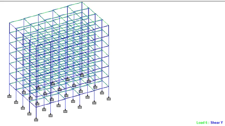
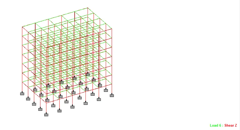
Step8: View Results
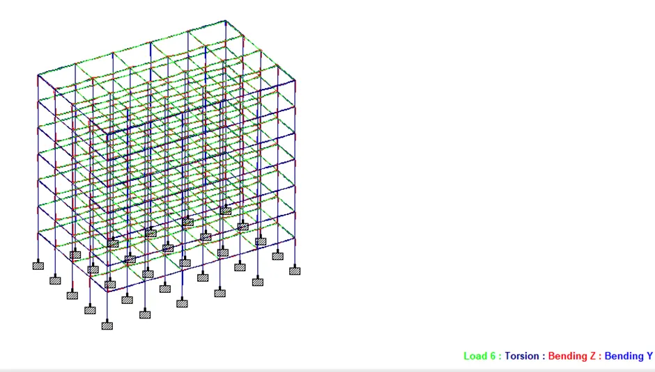
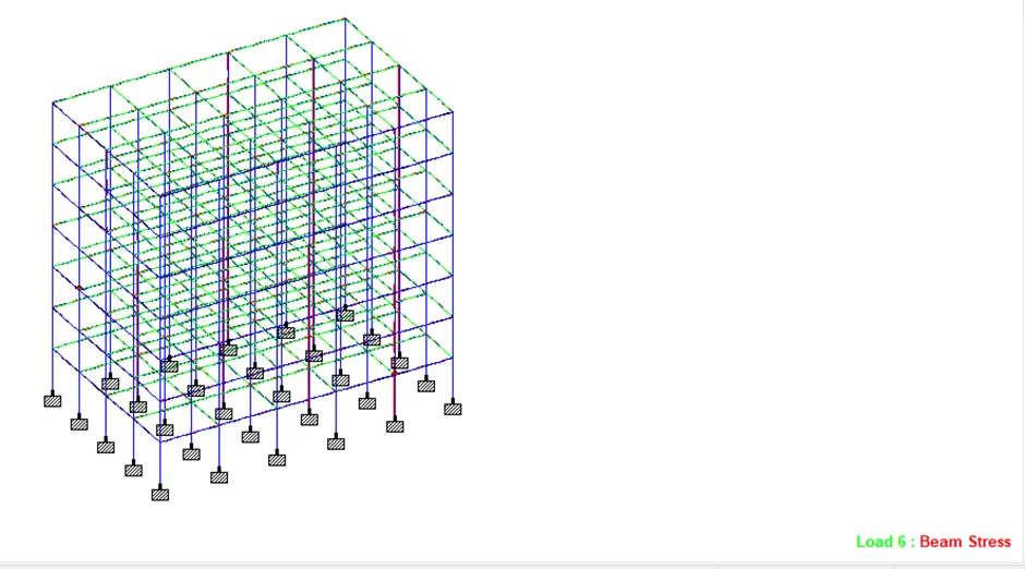
Step9: Design
Go to commands, select design, choose concrete design.
Change current code to IS 456.
Click on select parameters.
Add necessary parameters. Click on OK.
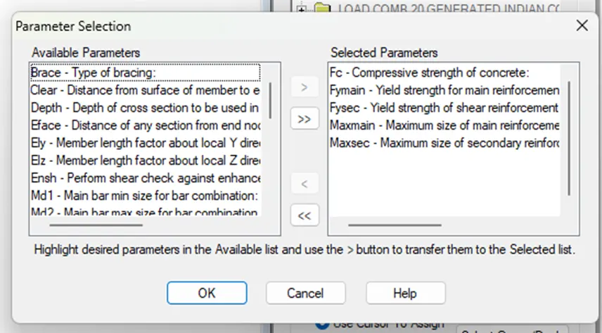
Click on define parameters.
Add values for each parameter.
Click on add and close.
Select commands option.
Choose design beam and click on add.
Choose design column and click on add.
Choose design slab/element and click on add.
Choose take off command, click on add and close.
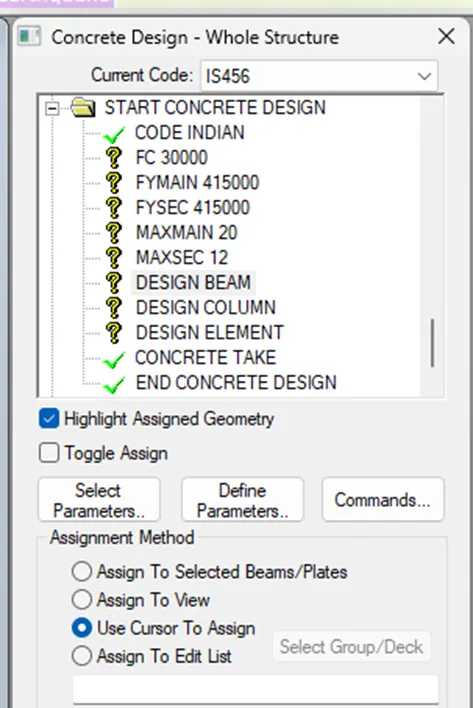
Select each design parameter and choose ‘Assign To View’ option, click on Yes and Close.
Select design beam, select beams parallel to X and Z, choose ‘Assign To Selected Beams’, click on Assign, Yes and Close.
Select design column, select beams parallel to Y, choose ‘Assign To Selected Beams’, click on Assign, Yes and Close.
Select design element, choose ‘Assign To View’, click on Assign, Yes and Close.
Go to Analysis/Print option, choose no print, click on add and close.
Go to Analyze tab and click on Run Analysis.
Go to post processing mode and click on done (if there are no errors).
Go to Foundation Design tab.
Select the primary load cases and click on include.
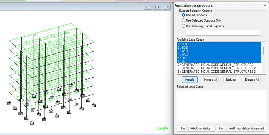
Click on RunSTAAD Foundation.
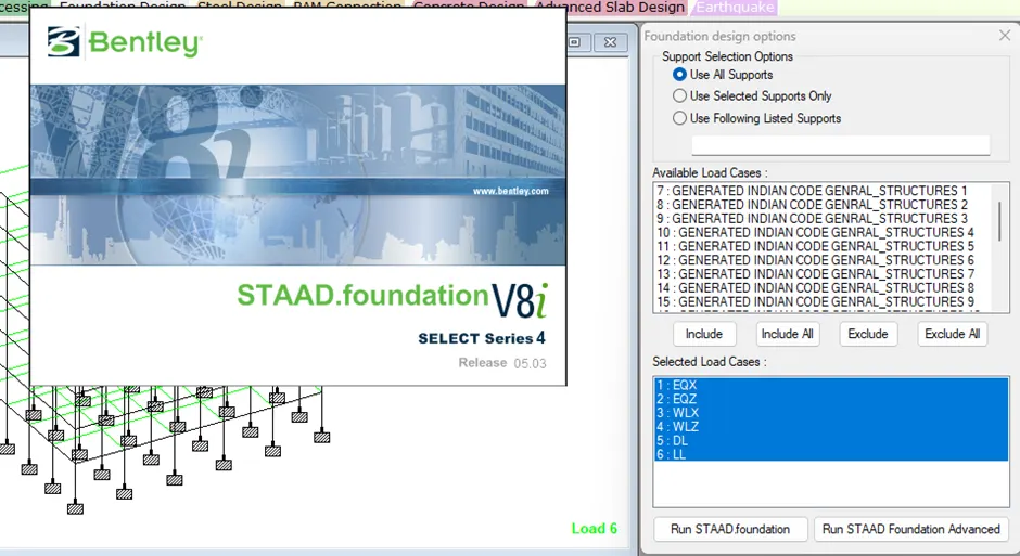
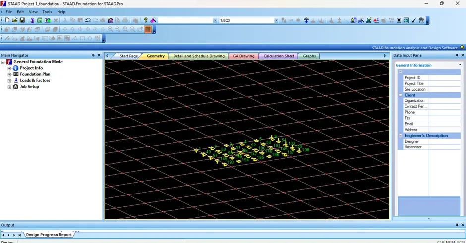
Go to General Foundation Mode.
Choose loads and factors option.
Click on Generate Load combinations.
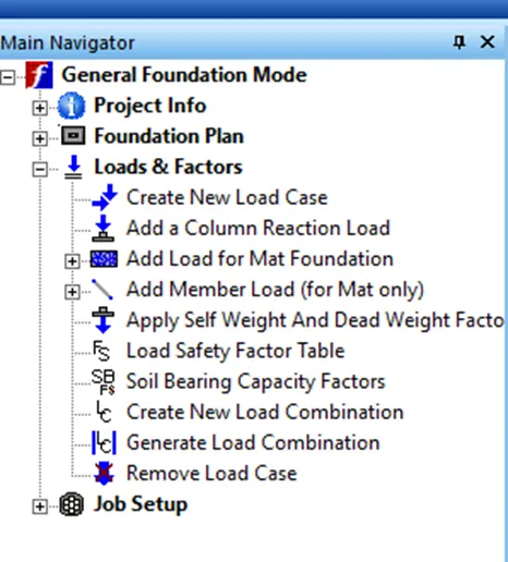
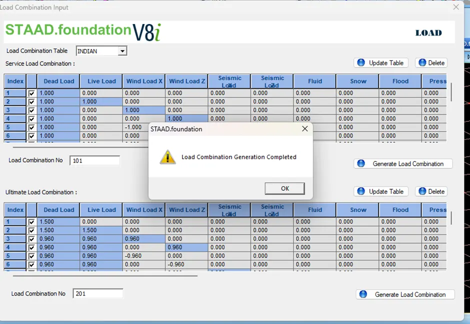
Load combination Input window appears.
Select the Indian code from load combination table.
Click on generate load combination for service load combination. Click on ok.
Click on generate load combination for ultimate load combination. Click on ok.
Select Job setup option from general foundation mode.
Click on Create a New Job option.
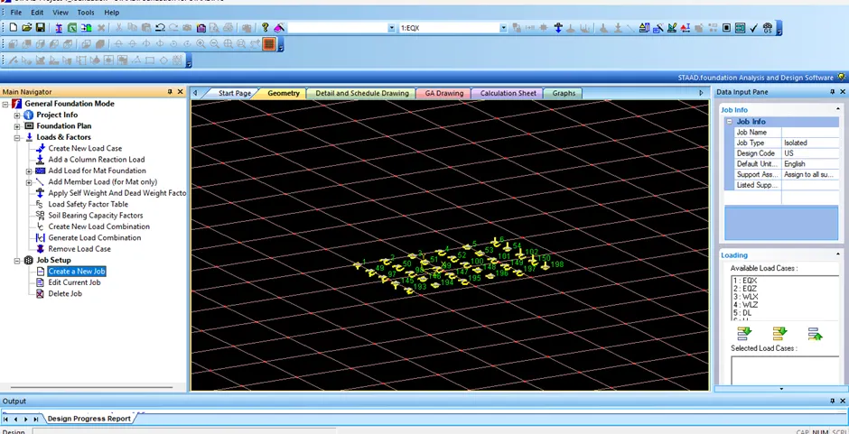
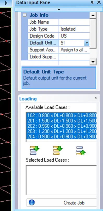
Give Job information
Job name – G+6 Foundation
Job Type – Isolated
Design Code – Indian
Default unit type – SI
Support Assignment – Assign to all supports
Include the generated load combinations. Click on create job option.
Go to Isolated footing job from General Foundation Mode. Click on Design parameters.
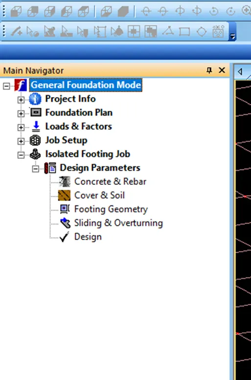
Select the required parameter and add data input.
Select cover and soil option. Input soil bearing capacity (180).
Click on Design option in Design parameters. Click on Yes.
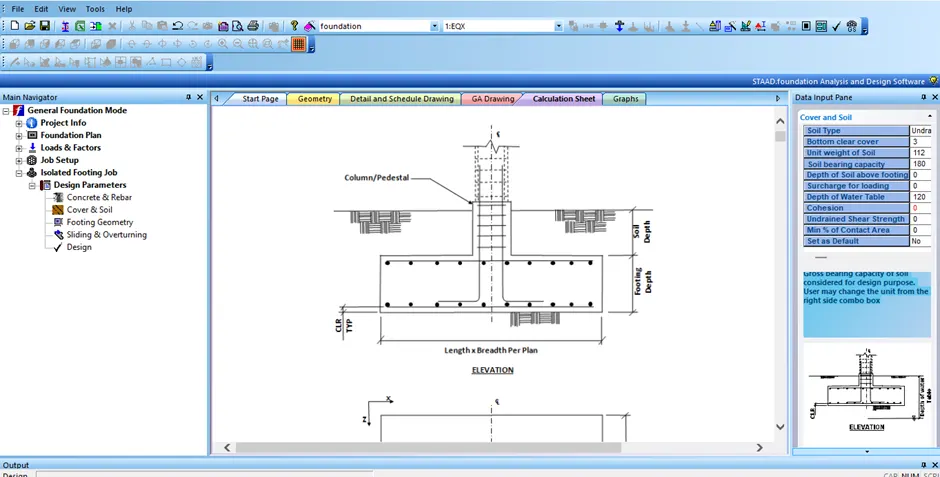
Click on required page to view.

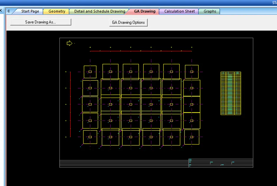
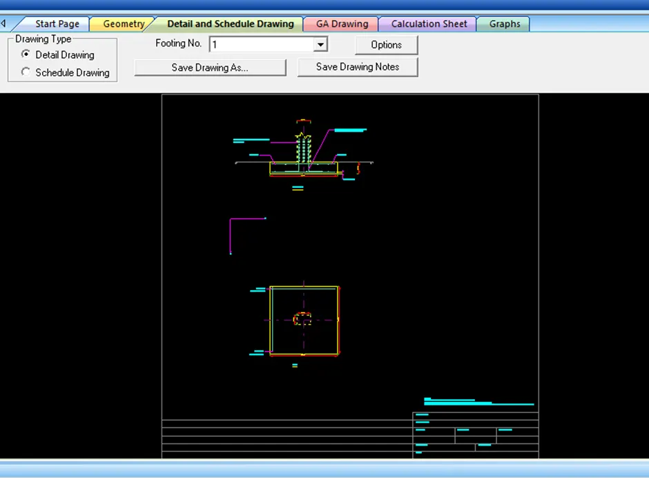
Result: A multi-storey Residential Building located in Bangalore is designed using STAAD Pro for the given specifications and the required results are obtained.
Dead load calculation:
As per IS 875 (Part 1)-1987 code standards the dead loads are calculated.
SelfWeight of slab = Thickness of the slab x Unit weight of RCC
= 0.15x 25 (Unit weight of RCC is 25kN/m3)
= 3.75 kN/m2
SelfWeight of Beam = Cross section of the beam x Unit weight of RCC
= 0.4 x 0.4 x 25
= 4 kN/m2
Selfweight of column = Volume of column x Unit weight of RCC
= 0.6 x 0.4 x 25
= 6 kN/m2
External wall load = Thickness of external wall x Unit weight of Brick x height of each floor
(assumed thickness of external wall is 0.23m, unit weight of brick is 19 kN/m3)
= 0.23 x 19 x 3.5
= 15.295 kN/m
Internal wall load = Thickness of internal wall x Unit weight of Brick x height of each floor
(assumed thickness of external wall is 0.125m)
= 0.125 x 19 x 3.5
= 8.31kN/m
Total wall load = 15.295 + 8.31 = 23.605 kN/m
Live load calculation:
Live loads are different for different buildings and structures. It keeps changing from time to time even on same structure. The minimum live loads per square meter area for different types of structures are given in IS 875(Part 2).
As per IS 875 Part 2, clause 3.1live/imposed load for residential building are:
All rooms and kitchens – 2 kN/m2
Toilet and bath rooms – 2 kN/m2
Corridors, passages, staircase including escapes and store rooms – 3 kN/m2
Balconies – 3 kN/m2
Wind load calculation:
The wind pressure intensities are calculated as per IS: 875 (Part-3) using the formula, (clause 5.4, IS:875 (Part-3)-1987)
PZ = 0.6 x Vz2
Where, Pz – Design wind pressure
VZ – Design wind speed
The design wind speed for any geographic location is calculated using the formula, (clause 5.3, IS:875 (Part-3)-1987)
Vz = Vb x K1 x K2 x K3
Where, Vb – Basic wind speed (Appendix-A, IS:875 (Part-3)-1987)
K1 – Risk coefficient factor (Table-1, IS:875 (Part-3)-1987)
K2 – Terrain & height factor (Table-2, IS:875 (Part-3)-1987)
K3 – Topography factor (Clause 5.3.3.1, IS:875 (Part-3)-1987)
For the given location i.e., Bangalore, Basic wind speed (Vb) = 33 m/s
Risk Coefficient factor (K1) = 1.05 (As the structure is residential building, from table 1)
Terrain & height factor (K2) = 0.83(X1=20,X=24.5,X3=30; Y1=0.76,Y=?Y2=0.93)
Topography factor (K3) = 1.0
Vz = Vb x K1 x K2 x K3
Vz = 33 x 1.05 x 0.83 x 1.0
Vz = 28.75 m/s
Now, Pz = 0.6 x Vz2
Pz = 0.6 x (28.75)2
Pz = 495.93 N/m2
Pz = 0.495kN/m2
Seismic Load Calculation (IS 1893-Part 1)
Design Base Shear VB = Ah.W
Ah=((Z/2).(Sa/g))/(R/I)
According to Annex E Bangalore comes under Zone II, hence zone factor for this location is 0.10.
Z = 0.10
Soil condition factor, Sa/g
T=0.09h/√d
Height of building = 24.5m
Base dimension of building along X = 16m
Base dimension of building along Z = 25m
T along X direction = T=(0.09x24.5)/√25 = 0.44 seconds
T along Z direction = T=(0.09x24.5)/√16 = 0.55 seconds
For hard soil, = (0.40S<T<4.00S) 1/T
= 2.5 (0<T<0.40S)
along X direction = 1/0.44 =2.27
along Z direction = 1/0.55 = 1.81
Considering the maximum value of
= 2.27
Response reduction factor (R)= 5.0 (from Table 7, Clause 6.4.2)
Importance factor (I)= 1.0 (from Table 6, Clause 6.4.2)
Horizontal acceleration coefficient
= ((0.10/2) x (2.27))/ (5.0/1.0)
=0.0227
Seismic weight:
Dead load of slab
=Area of floor x thickness of slab x density of RC
=25 x 16 x 0.15 x 25 =1500 kN
Dead load of Floor
= dead load of slab + dead load of floor finish
=1500 + (25 x 16 x 0.8) = 1820 kN
Dead load of Roof
= dead load of slab + dead load of floor finish +Terrace water proof
= 1500 + (25 x 16 x 0.8) + (25 x 16 x1.5) = 1500 + 320 + 600 = 2420 kN
Dead load of Beam
Weight of beam = size of beam x density of RC
= 0.4 x 0.4 x 25 = 4 kN/m
Length of beam along X direction = 5m
Length of beam along Z direction = 4m
Dead load of beam along X direction = weight of beam x effective span of beam x number of beams along X direction
= 4 x (5 - 0.3 - 0.3) x (5 X 5) = 440 kN
Dead load of beam along Z direction = weight of beam x effective span of beam x number of beams along Z direction
= 4 x (4 - 0.2 - 0.2) x (6 x 4) = 4.5 x 4.5 x 24 = 345.6 kN
Dead load of Wall
Self weight of wall = thickness of wall x density of masonry
= 0.23 x 20 = 4.6 kN/m
Length of wall in X direction (longitudinal) = 5 – 0.3 - 0.3 = 4.4m
Self weight of wall in X direction = 4.6 x 4.4 x (5 x 5) = 506 kN/m
Length of wall in Z direction (transverse) = 4 – 0.2 - 0.2 = 3.6 m
Self weight of wall in Z direction = 4.6 x 3.6 x (4 x 6) = 397.44 kN/m
Dead load of Column
Number of columns = 30
Size of column = 0.4 x 0.6 m
Density of RCC = 25 kN/m3
Selfweight of columns = 0.4 x 0.6 x 25 x 30 = 180 kN per meter height
Live Load
Live load on Roof = 0 kN (Clause 7.3.2 of IS 1893 (Part 1):2002)
Assumed live load on floor = 4 kN/m2
According to Table 8 of IS 1893 (Part 1):2002, percentage of imposed load is 50%.
Live load = 4 x 0.5 = 2 kN/m2
Live load on Floor = (25 x 16) x 2 = 800 kN
Total weight of the roof for storey = Dead Load + Live Load
= Dead load of (Roof slab + Beams + Columns + Walls) + Live load
= 2420 + 440 + 345.6 + 180 x 3.5/2 + 506 x (3.5-0.4)/2 + 397.44 x (3.5-0.4)/2 + 0
= 4920.93 kN
Total weight of Floor = Dead Load + Live Load
Dead Load of (Floor slab + Beams + Columns + Walls) + Live Load
= (1820 + 440 + 345.6 + (180 x 3.5) + 506 (3.5 - 0.4) + 397.44 (3.5 – 0.4)) + 800
= 6836.26 kN
Total seismic weight = 4920.93 + (6 x 6836.26) = 45938.49 kN
Design Base Shear VB = AhW = 0.0227 x 45938.49 = 1042.80 = 1042 kN
CONCRETE DESIGN (BEAM AND COLUMN)