Project 1
AIM:
To route the wiring harness for given engine.
Application of all packaging rules, Industry based practices studied in this course shall be
demonstrated in design.
Apply protection covering as required.
OBJECTIVE:
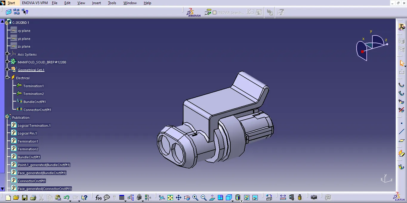
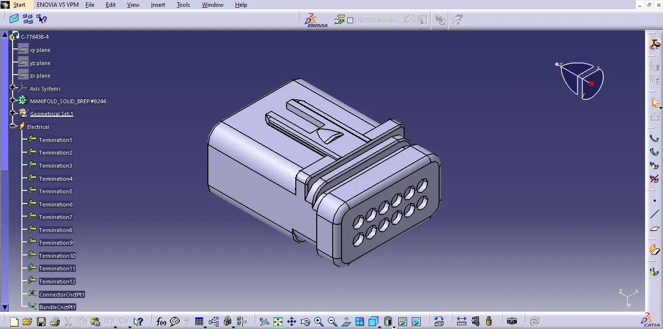
- Define all the mechanical connectors electrically and save it in the Catalogue.
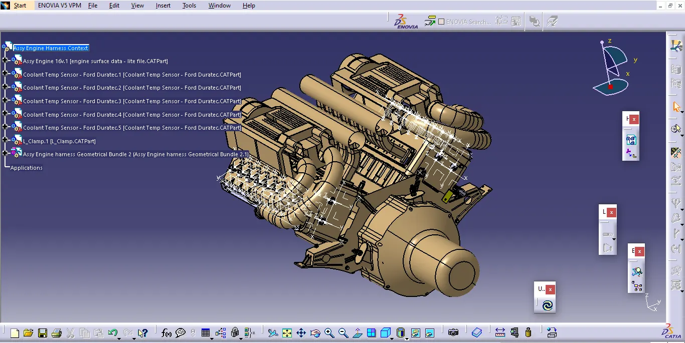
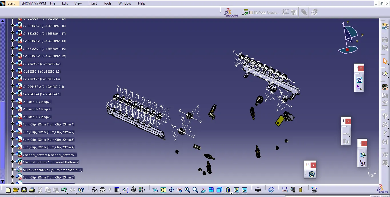
- Place all the connectors to the required positions on the given engine 3D CAD model
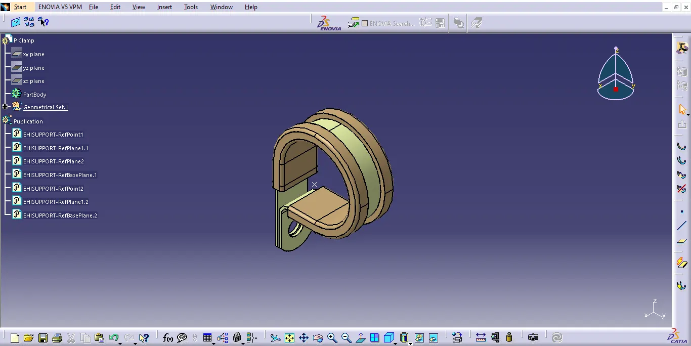
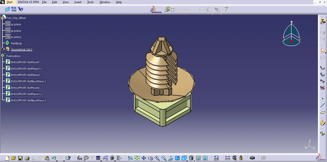
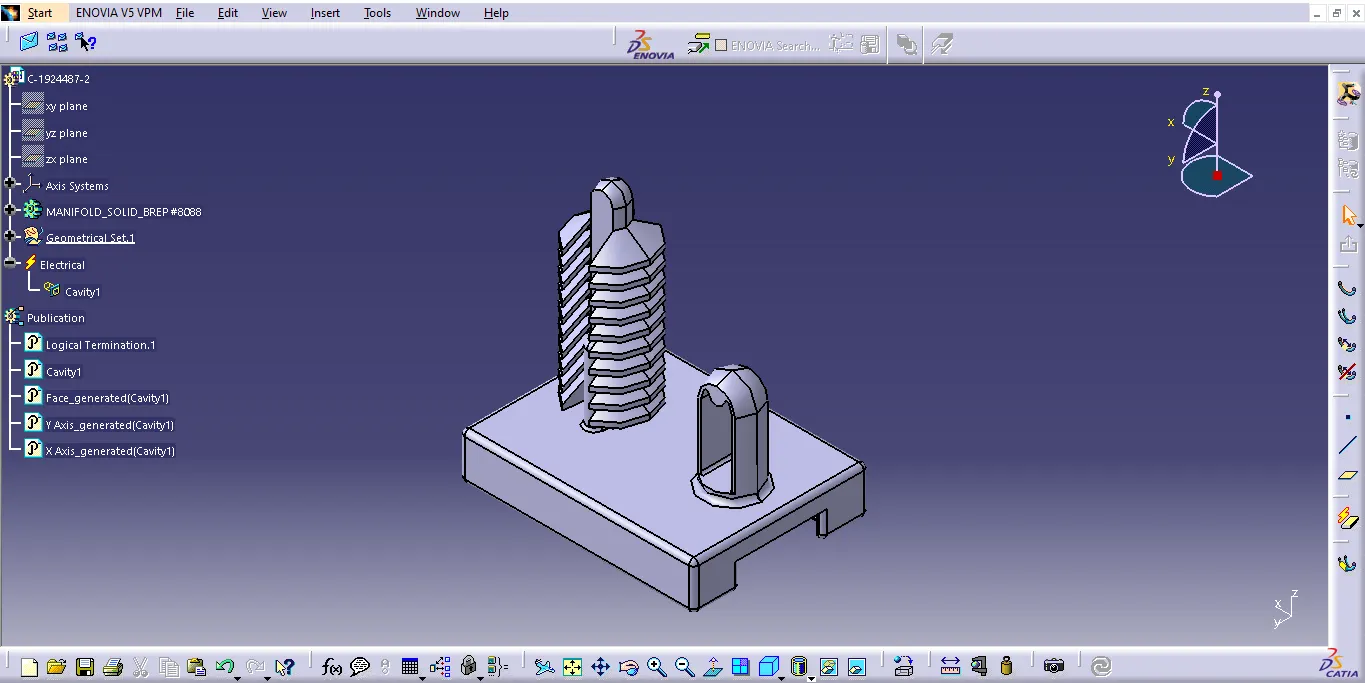
- Place P-Clamps and Fir Tree clips at the required position by following the packaging rules.
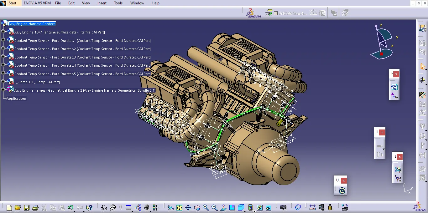
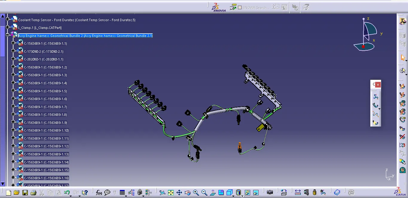
- Create the Wiring Harness Routing with all the electrically defined connectors and mounting equipments.
- Create branching points at required locations to create sub branches and connect to various connectors in the geometrical bundle.
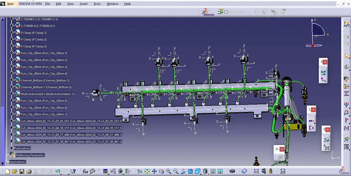
- Apply Protection coverings as required.
- Create Wiring harness flattening for the final geometrical bundle.
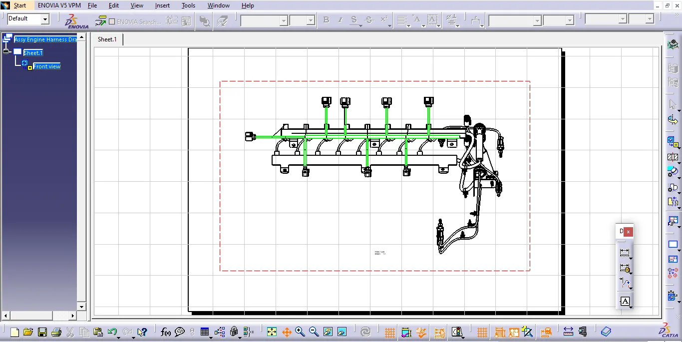
- Using the drafting workbench, create a drawing sheet with the flattened wiring harness.
Design crieria and packaging assumption:
- Wiring harness routing shall provide ease in manufacturing, accessibility, easy removal, and easy maintenance of attached equipment and wiring harness.
- Routing through small structural holes and openings shall be avoided, minimize chaffing and handling of the wiring harness during installation.
- Avoid the harness routing and clipping in the Blind zone of the Operator during harness assembly or in service.
- Routing shall offer protection against possible damage through common misuses such as being handhold and temporary support for test equipment.
- Provide additional slack to the harness according to the surroundings and harness bending requirements. Ensure the routing meets the clearance requirements with different surrounding parts.
- Avoid routing over the bolts, near to the bolted joints. It may damage the harness or puncture the harness. Keep harness away from panel mounting screws.
- Avoid harness routing near sharp edges, if not possible provide protection to the harness. The maximum distance between two clips on a straight branch is 200mm.
- Provide Clips and clamps if the harness is going to bend at multiple locations. The use of too many sheet-metal brackets should be avoided.
- The branch length should be more than 50 mm.
- Min distance between clip and branching point to be 25 mm. Min distance between two branch breakouts should be 50 mm.
Given:
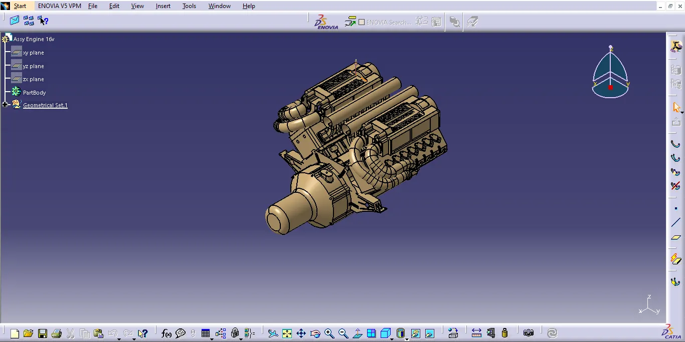
1.Engine:
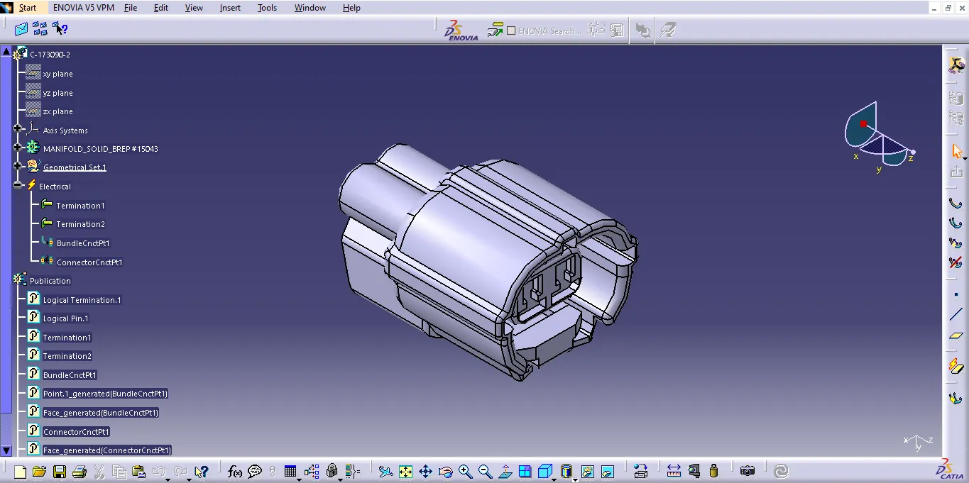
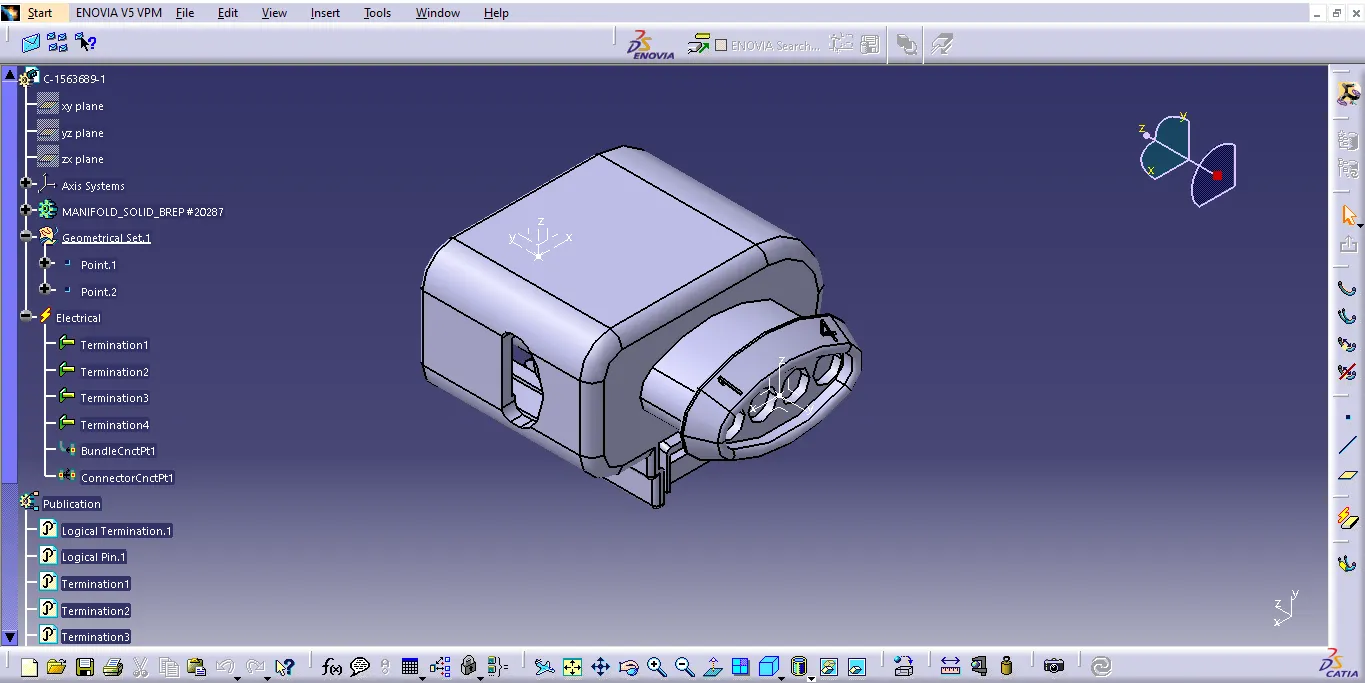
Defining all the Mechanical component into Electrical
Connectors:
2_Clips/Clamps
3_Channel
Routing the wiring Harness:
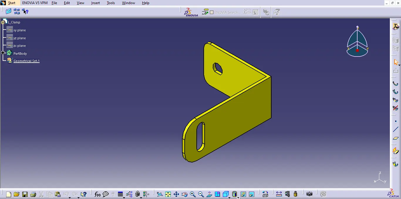
A sheet metal bracket was created for the interconnectionconnector to be placed near the
engine.
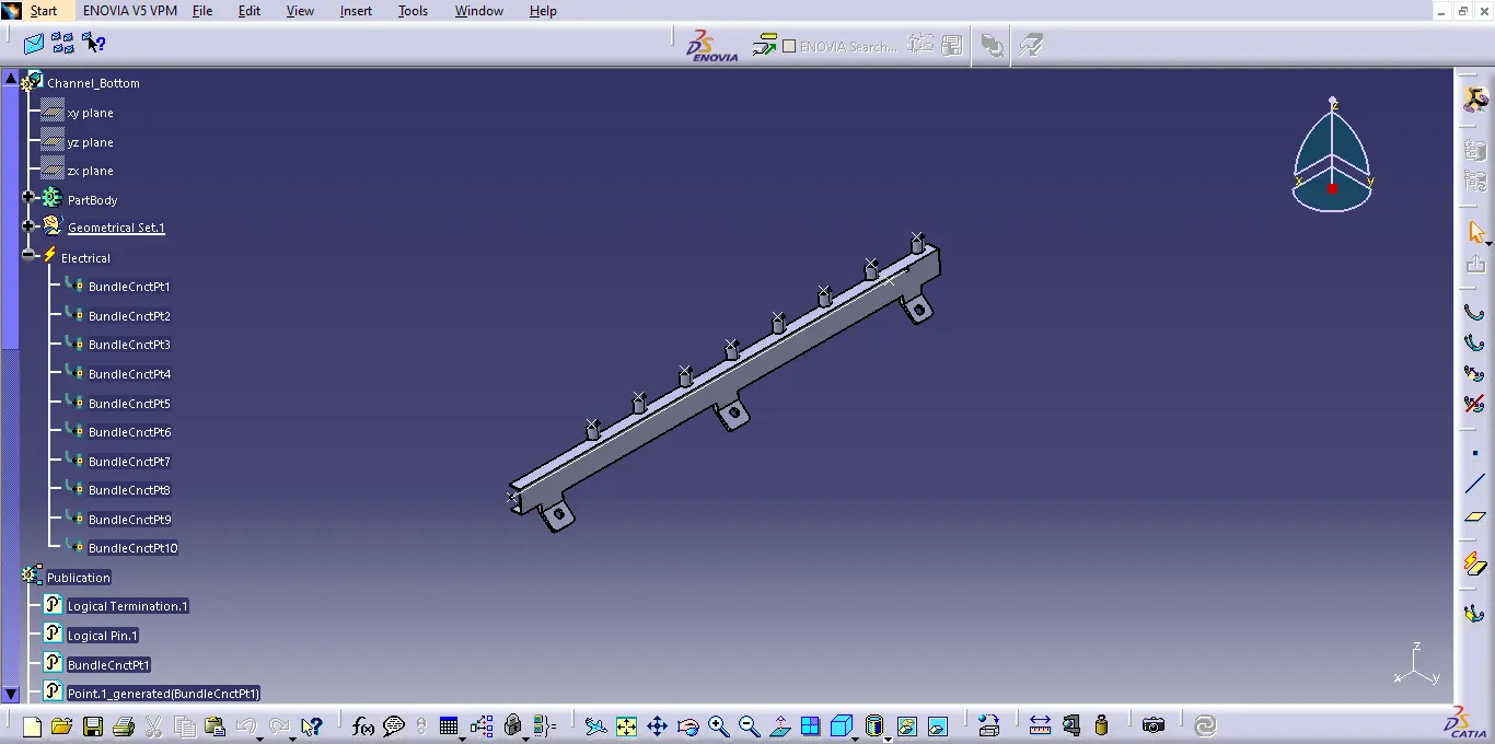
All the clamps and fir tree clips are positioned plastic channels were placed for connecting
the injection routing connectors.
Routing:
Protective Covering on Harness:
Wiring Harness Flattening:
Harness Drawing: