Project 1
Wiring Harness using Catia V5-Project 1
Objective:
Design and develop the Wiring Harness On Given V6 Engine and Prepare Flatten View drawing in CATIA V5. Application of all Packaging rules, Industry best practices studied in this course shall be demonstrated in design
Overview:
A wire harness, also commonly known as a wiring harness, is an external sheath employed to encase various types of electronic wires. Typically fabricated from thermoplastic or thermoset materials, wiring harnesses serve to shield cables from environmental factors.
Wiring Harness on Bugatti-W16 engine :
The Bugatti W16 engine is a quad-turbocharged,w16-engine,under their high-performance luxury sport car marque Bugatti, since 2005.
An Engine Wiring Harness comprises wires, cables, terminals, and connectors that regulate a vehicle's electrical system. It serves to transmit electrical power and control information to various components such as batteries, alternators, fuel injectors, fuses, audio systems, blower motors, and computers. Wire harness companies specialize in customizing the harness for specific locations, applications, and designs, ensuring seamless interconnection. Referred to also as a Cable harness, it embodies more than a mere aggregation of wires. It oversees critical functions within the engine, including the Engine controller, oil controller gate, transmission plug housing, air pipe sensors, pressure sensors, and water temperature sensors.
Engine wiring Harness Procedure:
- Define all the Connectors Electrically: Identify the types of connectors needed for the wiring harness based on the components and sensors in the engine system. Determine the electrical specifications and compatibility requirements for each connector.
- Place Connectors on the Engine 3D CAD Model: Integrate the connectors into the 3D CAD model at appropriate locations based on the wiring diagram and physical layout of the engine components. Ensure proper alignment and clearance for each connector.
- Install P-clamps and Fir Tree Clips: Determine the optimal locations for securing the wiring harness using P-clamps and Fir Tree clips. Follow packaging rules and guidelines to ensure proper spacing and organization of the wiring harness.
- Create Wiring Harness Routing: Define the routing path for the wiring harness, considering factors such as heat exposure, vibration, and interference with other components. Ensure that the wiring harness follows safe and efficient paths, avoiding sharp edges and hot surfaces.
- Create Branching Points and Sub-Branches: Identify locations where the wiring harness needs to split into sub-branches to connect various components. Implement branching points using junction boxes or harness splitters as necessary.
- Apply Protection Coverings: Determine areas of the wiring harness that require additional protection from heat, moisture, and physical damage. Apply protective coverings such as heat shrink tubing, braided sleeves, and loom tape as needed.
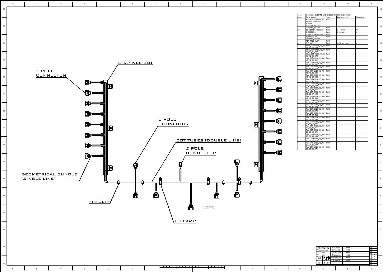
- Create Wiring Harness Flattening: Flatten the 3D model of the wiring harness to generate a 2D representation. Ensure that the flattened harness accurately reflects the geometry and layout of the actual wiring harness.
- Create Drawing Sheet with Flattened Wiring Harness: Utilize the Drafting Workbench to create a drawing sheet that includes the flattened wiring harness. Provide detailed annotations, dimensions, and part numbers for each segment of the harness. Include information about connector types, wire gauges, and routing paths on the drawing.
Steps to follow for wiring harness:
Step 1: Download the Engine CAD Data and Required Connectors CAD data from the provided Source.
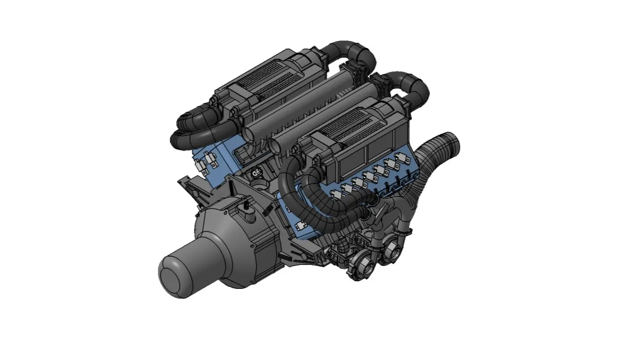
Step 2: Convert the Mechanical Connectors electrically by following the steps below:
- Download Connectors and mounting clip from the provided link.
- Enter the Mechanical part workbench to establish required geometrical parameters.
- Create Connector Connection point and bundle connection point on the necessary sides of the CAD part.
- Establish axis system on the Connector Connection point with Y Coordinate normal to the connector face, X co-ordinate towards the locking mechanism, and Z Co-ordinates facing to the top.
- Establish Cavity Connection Point for Connectors having the cavity for mounting clips.
- Define the following using the created geometrical parameters:
- Define part as electrical connector.
- Define bundle connection point.
- Define connector connection point.
- Define Cavity Connection Point.
- Download and define the plastic channel electrically.
- Create bundle entry point and exit point.
- Generate a line Curve between the main entry and exit points to enable multi-branching using external curve inside the channel.
- Establish 8 bundle entry points on the openings for connecting the injector connectors.
- Use the geometrical parameters to define the channel electrically using the define mounting equipment option.
- Define bundle entry points using the "define bundle connection point option."
- Create Channel symmetrical and define all the required geometrical parameters and Electrical Properties.
Step 4: Download and define P-clamp, L-clamp, and cavity clip.
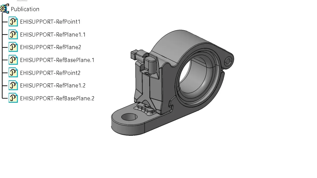
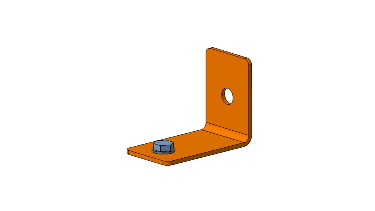
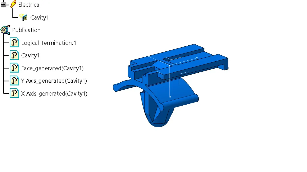
Step 5: Create a new Product file for Interconnection Connector and Cavity Assembly.
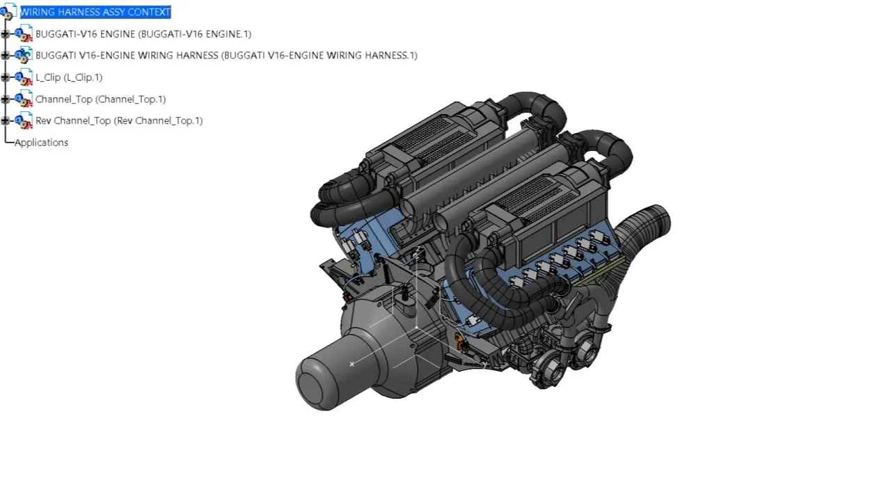
Step 6: Create the Context assembly:
- Include engine 3D-CAD data and the engine harness geometrical bundle.
- Add Channel top cover & L-clamp in the main context assembly.
- Switch into the Electrical Harness Assembly workbench and Electrically define the Geometrical Bundle Product file using the Define Geometrical Bundle Option before adding any parts.
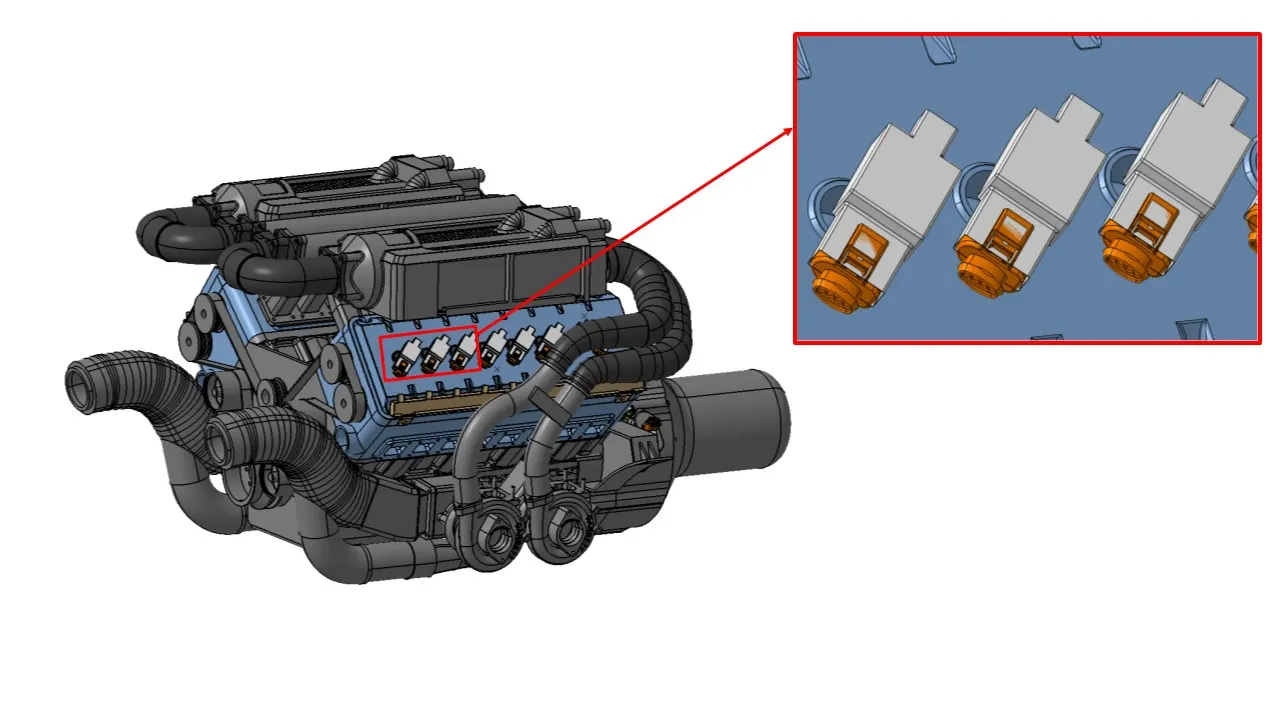
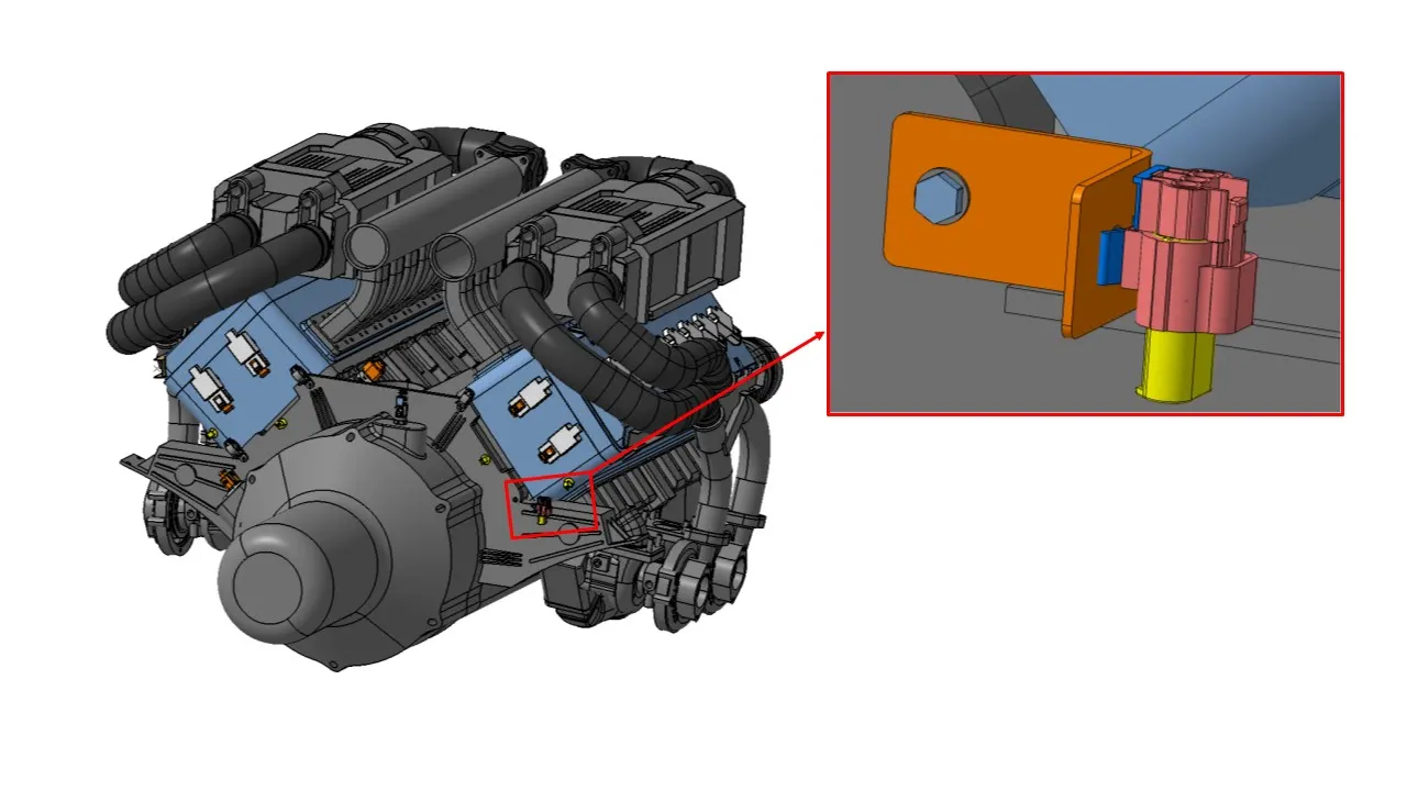
Step 7: Add 4 pole [1563689-1] connectors to all fuel injector sensors and camshaft sensors.
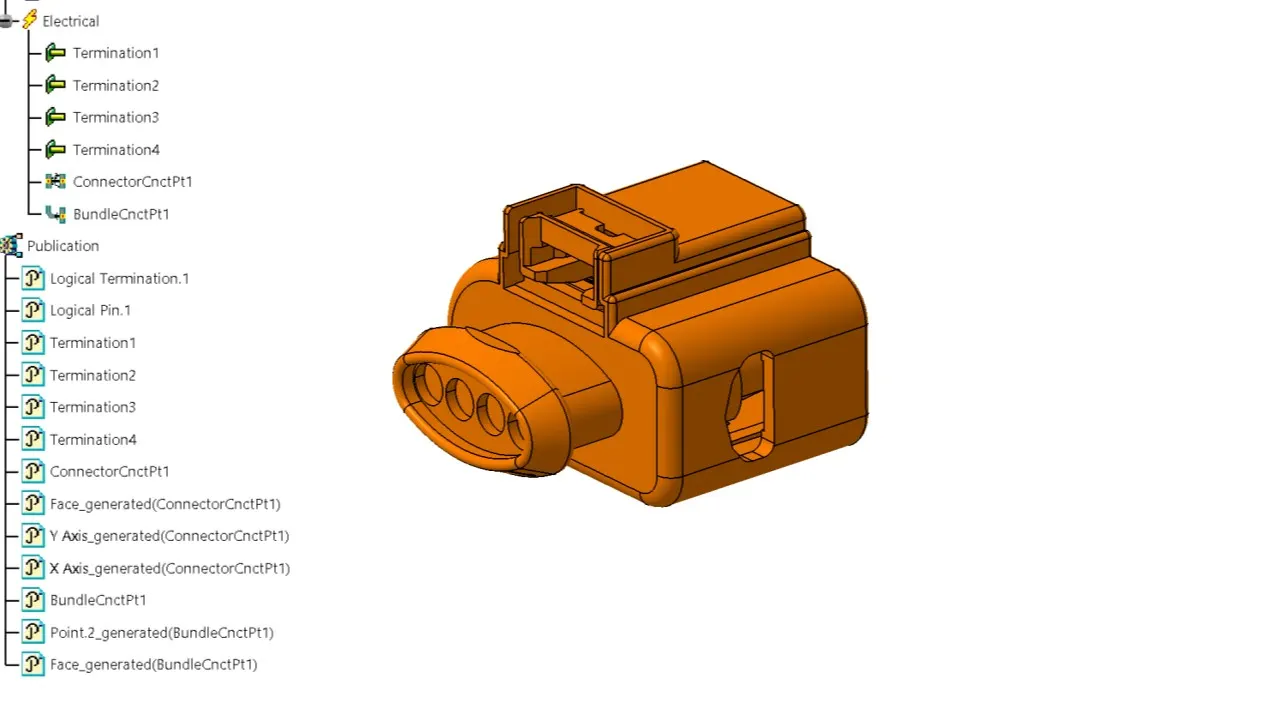
Step 8: Add all other Connectors for Sensors like Coolant heat Sensor, neutral position sensor, Speed Sensors.
- 2 Pole connectors:
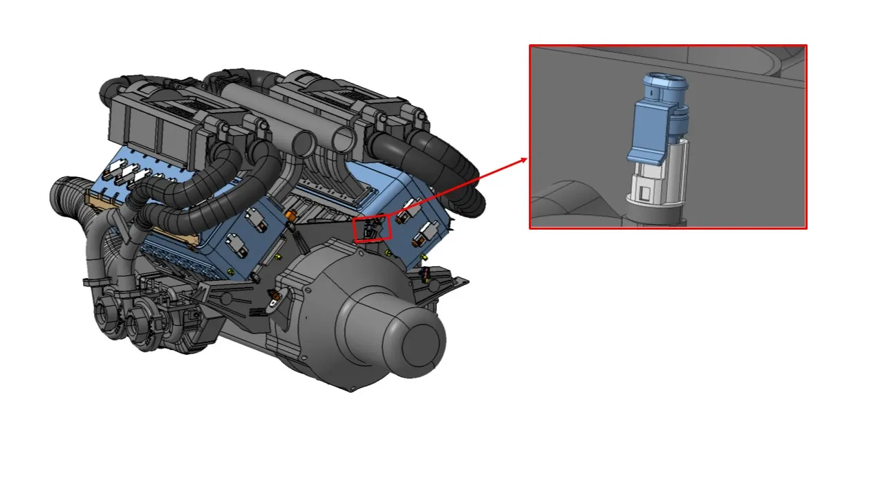
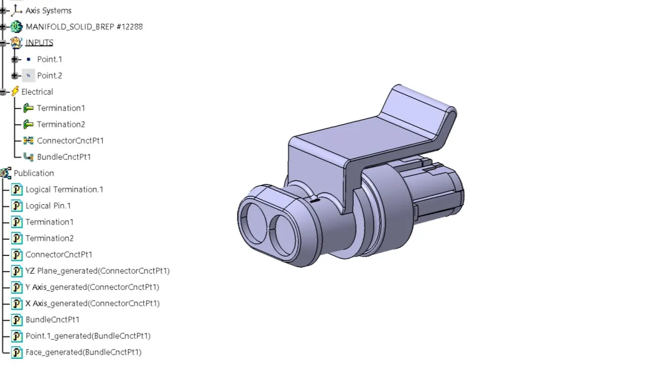
Step 9: Place the Interconnection connector and L-clamp Support.
- 3 Pole connectors:
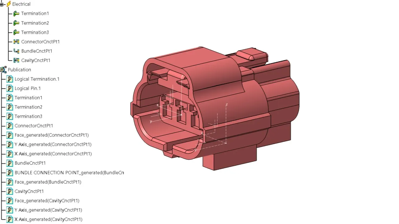
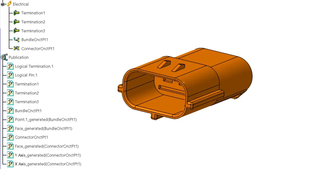
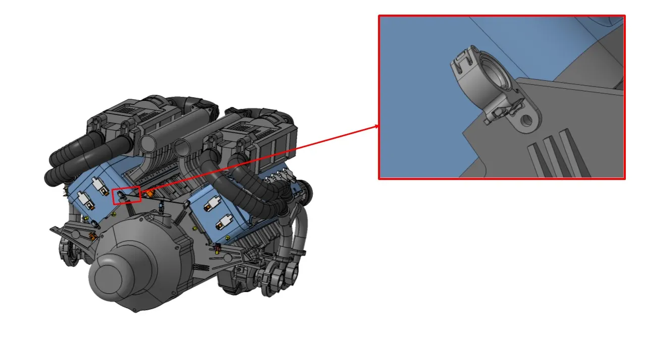
Step 10: Add P-clamps & Fir clips for proper Routing of the harness Bundle.
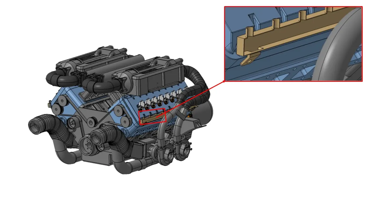
Step 11: Place Channels at the required locations.
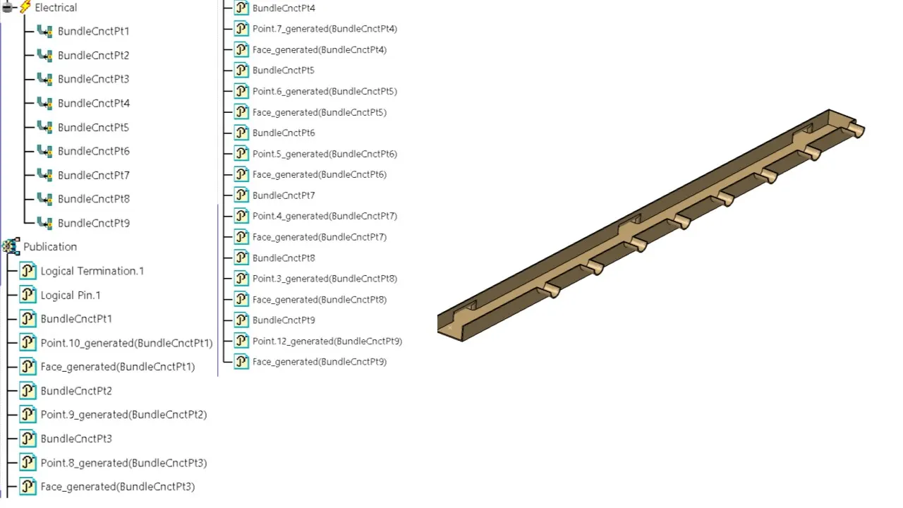
Step 12: Harness Routing Procedure for the channel:
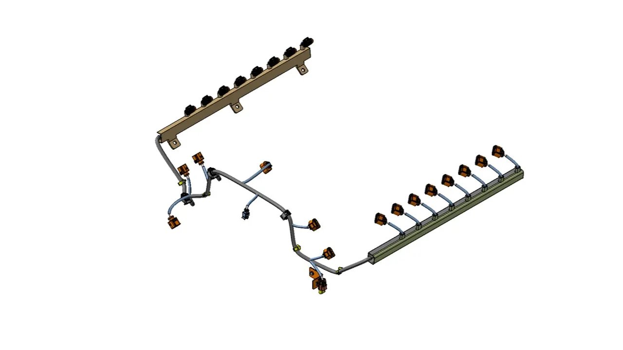
- Create multi-branchable bundle using the External curve option and select the line created earlier.
- After Creating Bundle Segment, create 8 Branch points inside the Channel for Creating sub-Branches for the injector sensor connectors.
Step 13: Perform Electrical Continuity check.
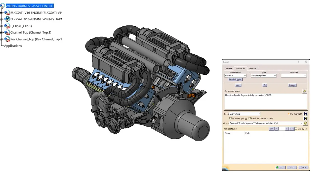
Step 14: Provide Protection Parts Wherever necessary.
Step 15: Wiring Harness Flattening:
- Create a new Product file and switch into electrical Harness flattening Parameters.
- Extract the geometric bundle from the Wiring Harness Context product file.
- Select all the Branches and Flatten the entire Geometric Bundle.
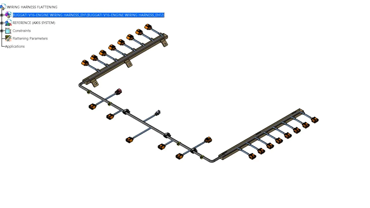
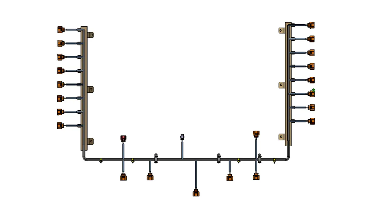
Step 16: Flattened Harness View in the Drawing Sheet:
- Create a Drawing File for the flattened harness product.
- Ensure bundles and protective coverings have different graphical representations.
- Insert the flattened harness product into the drawing sheet using the view option and selecting the front view command.
- Modify the Drawing Sheet with Required Parameters.
Onedrive link:[Data size is > 20MB]