Project 1
Design the mainline alignment.
Aim: To Design the mainline alignment
Procedure:
To design the alignment first we need to get terrain perfect without having zero elevation points and triangulated network. Attach the e-terrain file, row prop, and existing files. Turn on the background imagery and before that turn on the background imagery. Using the line commands draw a line on the end row. Copy it on the other side and using best fit create the mainline/centreline. Draw straight lines like this wherever possible and insert curves between them using curve commands with appropriate radius. Apply the civil rules. Give the feature definition to it.
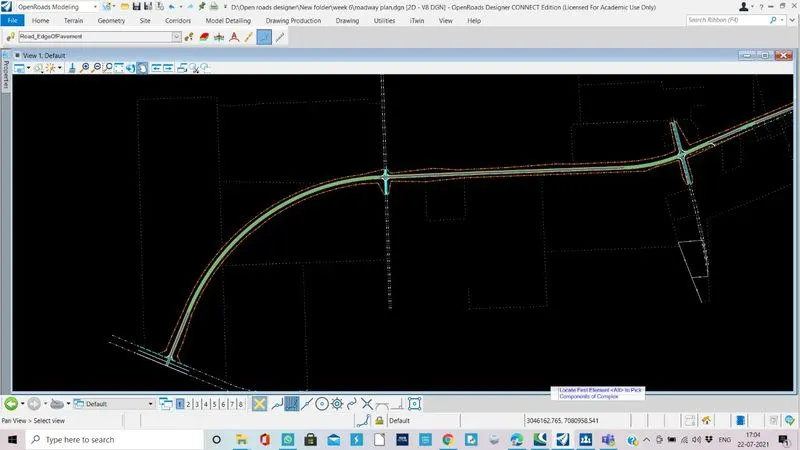
Result: Designed the mainline alignment
Create the existing ground profile of the above-created alignment. Design the proposed profile for the mainline alignment.
Aim: To Create the existing ground profile of the above-created alignment. Design the proposed profile for the mainline alignment.
Procedure:
Create a new file with seed 2D imperial training. Attach the project mainline.dgn file. Set the mainline active. Open the background (aerial) imagery. Set as aerial. Attach E_Terrain.dgn. Set it as an active profile (ORD>Terrain>Active>set active). Open the view. Try fit view, there we can see the existing ground profile. Using profile between points draw a line from starting point to ending point. Make the slope zero. Using civil accudraw draw the profile line. Apply the civil rules. Give feature definition to it. Make it active.
Result:
Created the existing ground profile of the above-created alignment. Designed the proposed profile for the mainline alignment.
Design alignments for the remaining 4 intersecting streets (use mainline alignment CL to tie in).
Aim: To Design alignments for the remaining 4 intersecting streets (use mainline alignment CL to tie in)
Procedure:
Use the proposed row to create the copy lines. By using best-fit draw the intersection mainline alignment. Apply the civil rules. Apply the feature definition to it. Tie it with mainline alignment.
Result: Designed alignments for the remaining 4 intersecting streets (use mainline alignment CL to tie in)
Design retaining wall alignment, top of the wall, and bottom of wall profile.
Aim: To Design retaining wall alignment, top of the wall, and bottom of wall profile.
Procedure:
Draw a line along the corridor of 200 feet in length. By using offset make it is required distance away from the edge line. Open the profile model for it. Create the profile according to the profile. Make it an active profile. Create a template for the retaining wall. Go to components>walls>Retaining wall 1 or 2 or 3. Select any one of them as per conditions.
The retaining wall is attached below. Please find.
Result: Designed retaining wall alignment, top of the wall, and bottom of wall profile.
Design the parking lot peripheral alignment, design the proposed profile (partly in cut and fill).
Aim: To Design the parking lot peripheral alignment, design the proposed profile (partly in cut and fill).
Procedure:
Create a rectangle using the line/ rectangle command. Apply the civil rules. Apply the feature definition. Open the profile model and create the profile using line command. Make it active. Create template drop (Kerb and gutter). Apply it to the lot.
The parking lot file is attached below. Please find.
Result: Designed the parking lot peripheral alignment, design the proposed profile (partly in cut and fill).
Export the alignments, profiles to Land XML and save them in the geometry folder.
Aim: To Export the alignments, profiles to Land XML and save them in the geometry folder
Procedure:
Use Export option. save it in folder.
Result: Exported the alignments, profiles to Land XML and save them in geometry folder
Unable to add screen shots because of the following reason.