Project 1
PROJECT 1
DEVOLOPING A COMPLETE WIRING HARNESS FOR V – TYPE ENGINE
Given Statement:
Route the Wiring harness on Given Engine and Prepare flattened view drawing in CATIA V5. Application of all Packaging rules, Industry best practices studied in this course shall be demonstrated in design. Apply Protection coverings as required.
Available connector 3D data can be used, or you can download the connectors from www.te.com
Prepare & submit all necessary reports like clearance, Clipping/Clamping selection, Harness fixing requirements, Harness continuity, and Assumptions if any along with CATIA 3D data.
OBJECTIVE:
Developing a complete wiring harness for v – type engine by following the wiring harness rules and regulations, creating a Electrical Harness Flattening and preparing a Flattened view drawing sheet by using CATIA workbench.
ABSTRACT:
Wire harness design includes the electrical functions and electrical requirements to be achieved by the wire harness, the size of the wire harness, the protection and fixing methods, and the connection between the wire harness and between the wire harness and the vehicle electronics The.
The wire harness assembly process is a complicated manufacturing activity, which is becoming more complex because of the evolving nature of mechatronic and electronic products that require more connectors, sensors, controllers, communication networking, etc. Furthermore, the demand for wire harnesses continues to grow in all industries worldwide as the majority of equipment, appliances, machinery, vehicles, etc., are becoming “smart” (i.e., more mechatronic or electronic). Moreover, most of the wire harness assembly process tasks are done manually, and most of these are considered non-ergonomic for human assembly workers. Hence, the wire harness manufacturing industry is faced with the challenge of increasing productivity while improving the occupational health of its human assembly workers.
INTRODUCTION:
In this project, a complete wiring harness assembly is developed for a V – type engine using the electrical workbenches available in CATIA V5. The electrical wire bundles are packaged and routed following the industry best practices design criteria. The geometric bundle contains the accessible connectors that are correctly mounted on the fuel injectors, camshaft sensors, engine coolant, neutral position, and camshaft sensors. After developing the assembly, a flattened and drawing views are generated.
WIRING HARNESS:
The wiring harness is the combination of electrical cables, or assembly of wires, that connects all electrical and electronic (E/E) components in the automotive vehicle, like sensors, electronic control units, batteries, and actuators. The wiring harness handles the energy and information flow within the E/E system to full-fill primary car functions, such as steering and braking as well as secondary car functions, such as ventilation and infotainment.
A wiring harness routing structure includes a wiring harness routing member configured to be attached to a vehicle body and a protector that accommodates and holds a wiring harness. The protector has a recess shape in which the protector is opened in one direction in a sectional view. At least one of the wiring harness routing members and the protector includes a fixing mechanism that fixes the protector to the wiring harness routing member. The protector and the wiring harness routing member are configured to be integrated via the fixing mechanism.
Electrical Harness Flattening operation is used for converting the 3D format of the wiring harness geometrical bundles into associated 2D drawings, which will be taken as a reference during the various stages of manufacturing, assembling, installation and servicing of wiring harness.
Once a product is ready to manufacture, its design must be precise or it risks costly errors and delays. Collaboration is the essential key to successful documentation and design between harness designers and manufacturing. CATIA – Electrical Wire Harness Flattening provides automatic and complete flattening of 3D Electrical Harnesses for manufacturing documentation in a concurrent engineering environment.
MATERIALS CHOOSE FOR WIRING HARNESS:
There are various components that are teamed up to make a wire harness; and you must be sure about the choice of each one of these. And, in order to make the right choice, you must first understand all the environmental conditions and other factors that your wire harness or application will be subject to. Will the environment be highly humid or extremely hot? Will the product have to bear excessive pressure or abrasion? After you understand the requirements completely, you will be in a better position to make the right choice. Here is a complete list of all the components that you need to consider while planning up a customized wire harness; and each one comes with a list of the various options available.
Conductor:
Conductor is the very important material in a wire harness that allows the flow of an electrical current in one or more directions within the wire. The most common material used is copper, but there are many other options like nickel, silver, tin, and aluminium too.
Insulation and Jacketing:
Insulation is a covering that protects the conductor against any kind of current leakage. Also, any incoming physical abuse can be prevented with the help of insulation. Over the insulation comes another protective layer of jacketing, which is designed to protect the wires against chemicals, moisture, and mechanical damage. The most popular insulating and jacketing materials used include –
· PVC – The material can perform effectively at temperatures between -20 to 105°C, and has good fire resistance, chemical resistance, UV resistance, durability, and flexibility.
· Polyethylene and polyurethane – Both these materials can perform effectively at temperatures between -60 and 80°C, and have good chemical resistance, UV resistance, durability, and flexibility; but are very poorly resistant to fire.
· Thermoplastic rubber or elastomer – The material can perform effectively at temperatures between -40 and 90 °C, and is surprisingly good in terms of fire resistance, chemical resistance, UV resistance, durability, and flexibility.
Fillers:
Fillers may be used to strengthen the cable by supporting the outer layers, and increasing the flexibility of the construction, while also offering a rounder and smoother construction. The most popularly used fillers include –
· Polyethylene, which is a lightweight material that can be easily moulded, making it ideal for longer wires.
· Cotton, which is a low-cost solution as the durability is comparatively lesser, but the flexibility offered is good.
· Steel, which is highly strong and durable, and can be tied off at either end of a harness, to transfer any force the wire encounters, away from the conductors, and onto a housing inside the harness.
· Foam, which can be made out of a variety of materials, effective for filling in small spaces between wires, and retaining the wire harness shape.
METHODOLOGY:
There are several factors to consider when designing a cable assembly or wire harness for the given application and the entire vehicle wiring harness is designed accordingly.
Harness passes through many areas where it requires protection against heat, dust, moisture etc. Wire harness protection prevents damage caused by wire vibration damage, abrasions and incidental contact with other pieces of heat producing equipment.
RULES FOR WIRING HARNESS:
· Wiring harness should be routed in such way that it is easy to assemble and access.
· Easy manufacturing, installation, removal and maintenance have to be considered while designing the wire harness.
· wiring Harness should be kept away from sharp environment like edges, corners etc.
· Avoid harness routing and clipping in the blind zones or hard to reach areas during harness assembly or service.
· Provide additional slack if needed according to the surrounding and harness bending requirement. If harness is passing through the closures/doors or tail gates then envelope dimensions during opening and closing of doors shall be considered to provide the slack. Check the harness slack requirements with open and close conditions to avoid excess slack.
· Routing through small structural holes and openings shall be avoided. To minimize chaffing and handling of the wiring harness during installation.
· It should be made sure that there is no case of fouling while designing the wiring harness in the CAD environment. Additional mounting equipment’s like clips/clamps may be used to avoid fouling.
· Use of rubber grommet is recommended if harness is passing through sheet metal panels. Example- firewall, passing to doors.
· The branch length should be minimum 50 mm.
· The minimum distance between the clip and branch point should be at least 25 mm.
· The minimum distance between the two branch points should be at least 50mm
· Clips/clamps used for the wiring harness should be easily available in the market to avoid extra cost for custom mounting solutions.
MODELING:
The following procedure and steps is followed while routing the wiring harness to the v – type engine.
STEP 1: Download the all-CAD files and required connectors from the given statement.
STEP 2: In this project I used the dummy connectors and tried the routing wiring harness from the best industry practices.
STEP 3: define all the connectors, p – clamp and fir – tree clips electrically and mounting equipment.
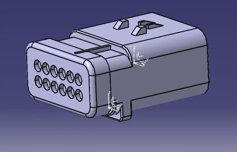
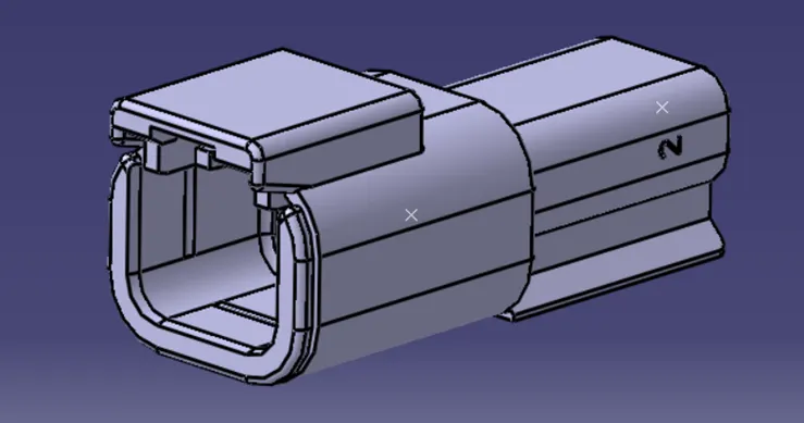
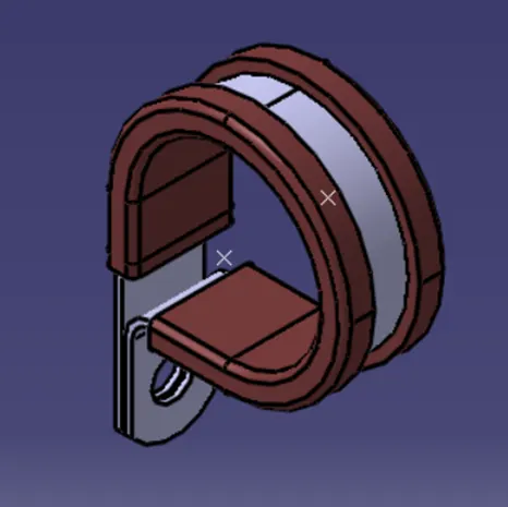
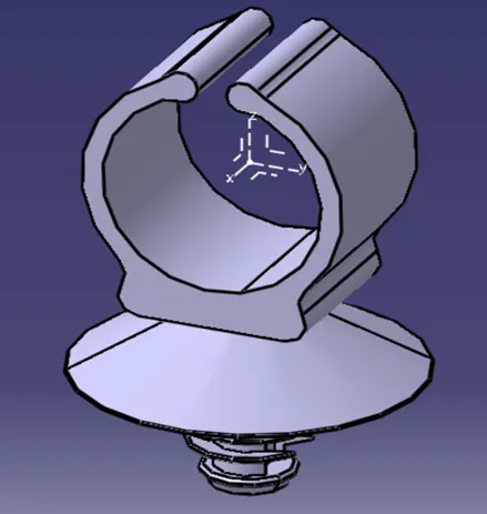
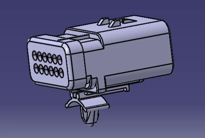
STEP 4: Create a context assembly and extract the engine file in the context assembly. Create a new product file in the context assembly.
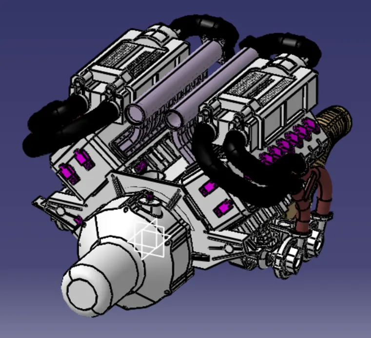
STEP 5: Extract all the connectors, p – clamp and mounting clips in a created product file.
STEP 6: Arrange all the connectors, p – clamp and mounting clips in required places.
STEP 7: Start the routing from the Inter – Connection connector to the P – clamp and others by creating the branch points.
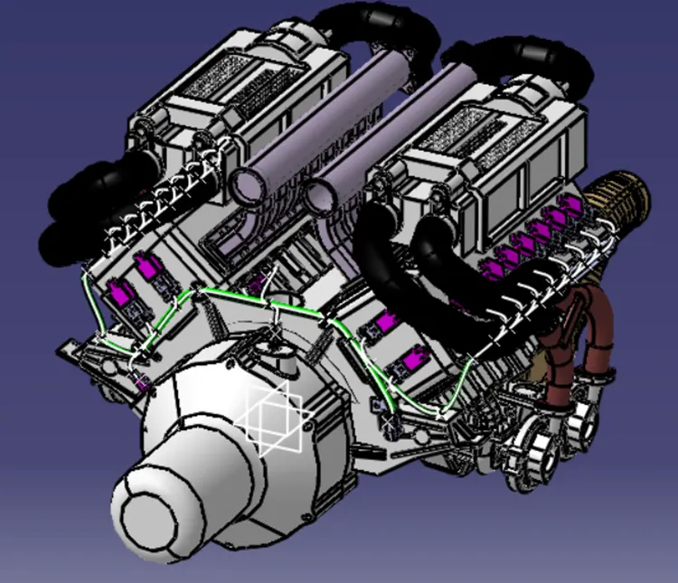
STEP 8: Apply the protective coverings where it needed, if 10 mm dia of wire use the protective covering as 15 mm dia. Maintain the dia of corrugated tubes greater the wire dia.
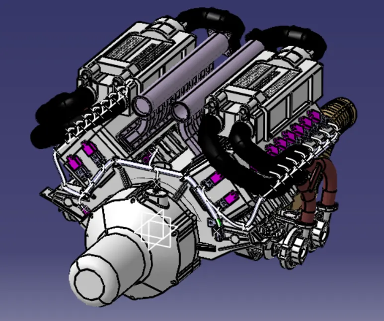
STEP 9: Save all the files using the save management option.
STEP 10: Create another product file for the Electrical Harness Flattening by applying the required parameters and extract the geometrical bundle from the engine context assembly.
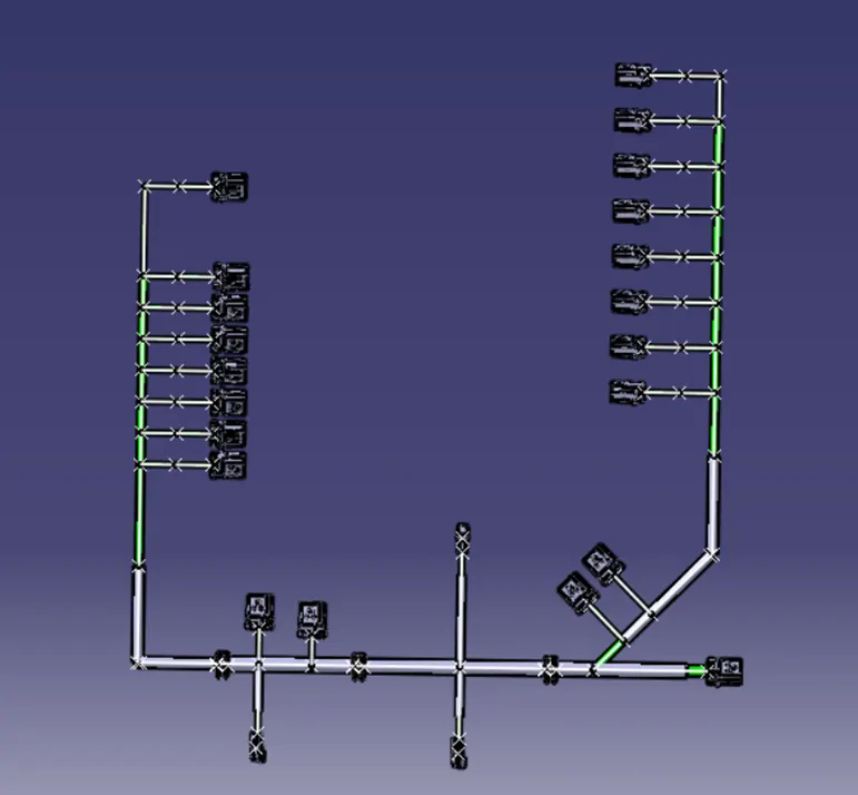
STEP 11: Create a new drawing file for the flattening view of the engine wiring harness. And create the bill of material sheet.
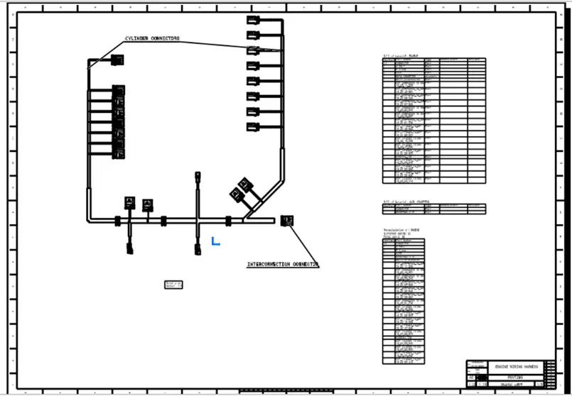
RESULTS & CONCLUSION:
· As in the part of working in this project we learn how to given the wiring harness routing connection to the automotive vehicle’s by following the packaging rules of wiring harness.
· Developing of wiring harness routing for the V – Type Engine assembly part, Electrical Harness Flattening and Creation of Flattened view drawing sheet is completed by applying some wire packaging rules from the best industry practices.
................................................Thank you...................................................
While i am tried with the channel by defining it as support part but error was pop up. So i am tried this by keeping the channel out side the goemetrical bundle and after this the problem was solved i am uploading the problem screen shot
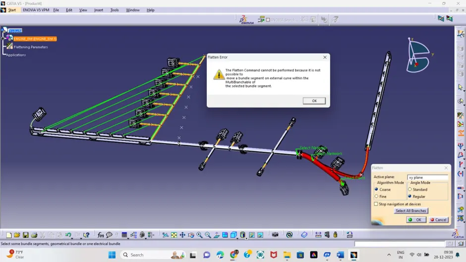
And when try to submit the zip file of all the files its size was 60 mb but here it shows less than 20 Mb so I am uploading different part files Thanks for understanding regarding student @skill - lync