Week 8 - Challenge 2 - Switch Bezel Design
CHALLENGE 2
SWITCH BEZEL COMPONENT ( REST SURFACE)
AIM: To create the SWITCH BEZEL plastic component through the given class A surface. To begin with, the tooling axis for the given class A surface and make the draft angle for it and also do draft analysis.
Take the thickness for the component as 2.5mm
Tooling axis:
First ensure the class-A surface is properly joined and has no discontinuity on it. For this we can use boundary command or join command.
Analyse the model manually or visually to see which direction is most suitable for tooling axis
As in 3D view we can see 2 holes and a flat surface, we can directly take the tooling axis perpendicular to that. But to be sure, let us analyse from all the views. The below images of the front side and top views shows the areas that we have to keep in mind while choosing tooling axis.
In X- axis
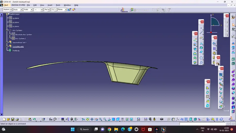
In X axis view walls only visible and the it was not suitable for the tooling axis.
In Y – axis
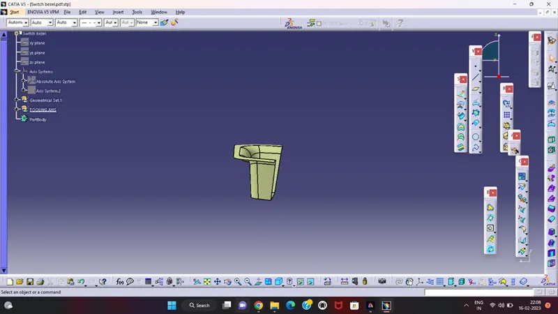
In Y axis view one part only visible so it can also not visible for the tooling axis.
In Z – axis
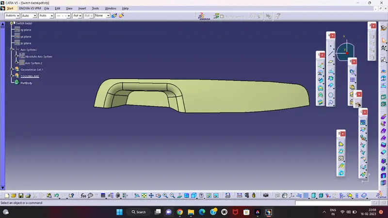
In Z axis view all the surfaces visible clearly and this direction is suitable for tooling axis.
In most of the cases Z direction is perfect for the tooling axis.
Creation of tooling axis is to first intersect the object in YZ and create the lines and bisect each other and create the line at the midpoint and again intersect in ZX direction and create the two lines and make it as iso constrained and last for that again take two lines which we create from in YZ and ZX direction and bisect each other and this line is the tooling axis for the Switch Bezel plastic component.
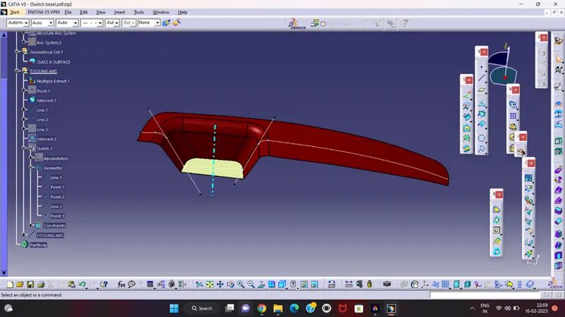
DRAFT ANALYSIS: For Draft Analysis, first go to 'Insert'>'Analysis'>'feature draft analysis'. Align the tooling axis with the compass. Click on the surface and see that the surface is within the permissible limit of the draft values. The surface should be green and in the column proper value (3deg) should be inserted.
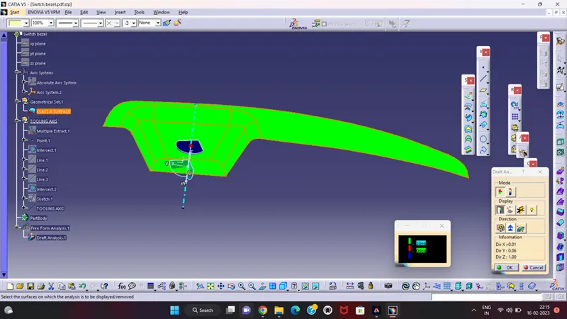
- Tree Structure
- Proper Tree Structure
- Geometrical sets have a proper name based on the sketches present inside of it
- All the sketches created under the Geometrical set
- Using the Close Surface feature to make a solid body from the surface.
- Publications: Using the publication option and publish the below
- Tooling Axis
- Class A, B, and C surface