Week 8 - Challenge 1 - Base Bracket Design
BASE BRACKET CHALLENGE
AIM: Create the Base Bracket Plastic component through the given Class-A surface. To begin with, the tooling axis for the given Class-A Surface should be created meeting the requirements of the draft angle and at the end perform the Draft analysis on the model.
A SURFACE MODEL:
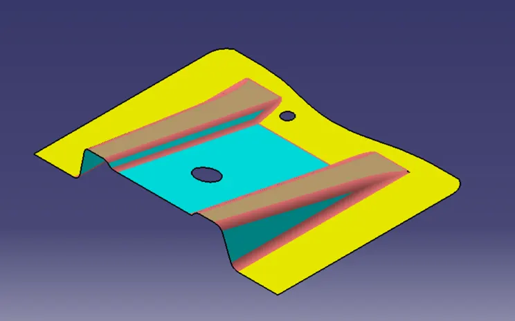
TOOLING AXIS: First ensure the class-A surface is properly joined and has no discontinuity on it. For this we can use boundary command or join command.
Analyse the model manually or visually to see which direction is most suitable for tooling axis
As in 3D view we can see 2 holes and a flat surface, we can directly take the tooling axis perpendicular to that. But to be sure, let us analyse from all the views. The below images of the front side and top views shows the areas that we have to keep in mind while choosing tooling axis.
X DIRECTION:
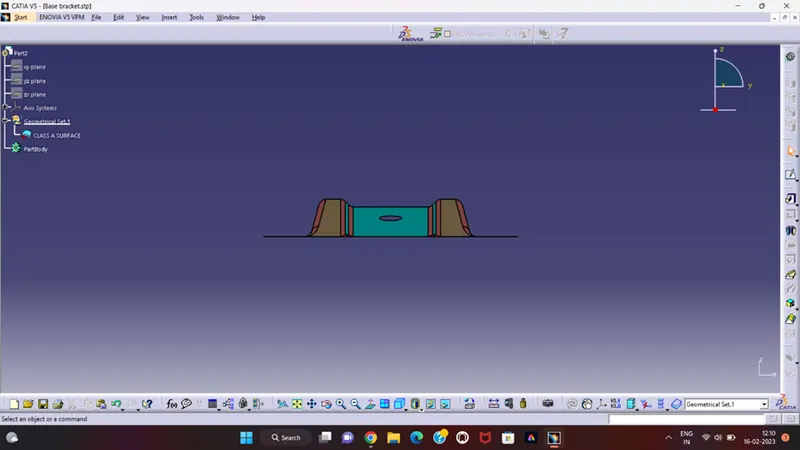
As from X axis view we cannot see one hole so we cannot take axis along this. If We use tooling axis on this direction then side core have to use for this part, that will be more tough.
Y DIRECTION:
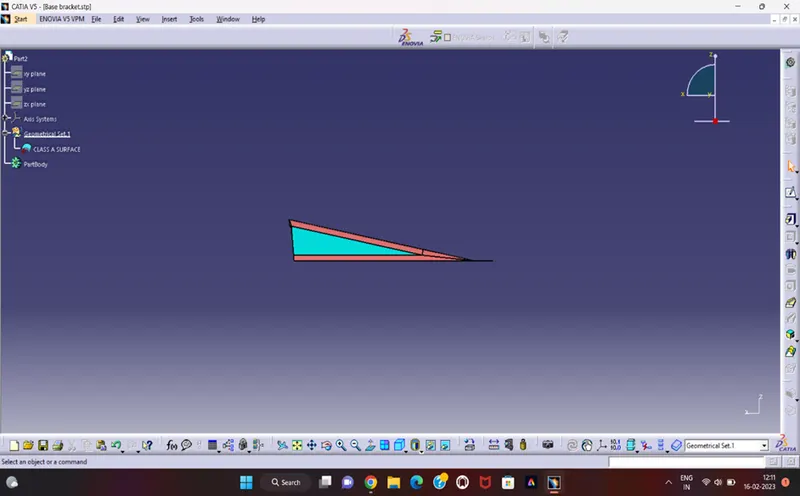
In Y axis view we cannot see any holes so here too we cannot take tooling axis and as X axis tooling direction here also side core will be used, if tooling direction is along Y.
Z DIRECTION:
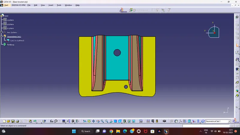
in Z we can see 2 holes and flat surface so we can take tooling axis. In this tooling axis no side core will be used.
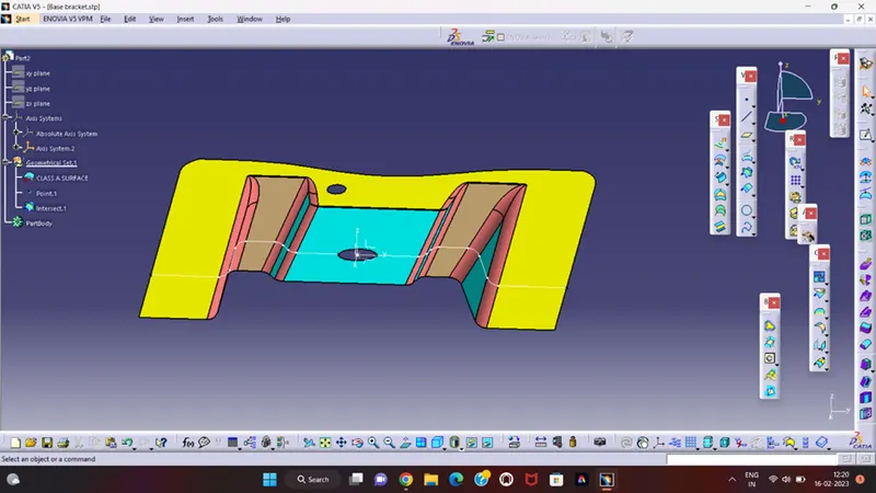
Creation of tooling axis is to first intersect the object and create the lines and bisect each other and create the tooling axis. The tooling axis is used for the draft analysis and injection moldings.
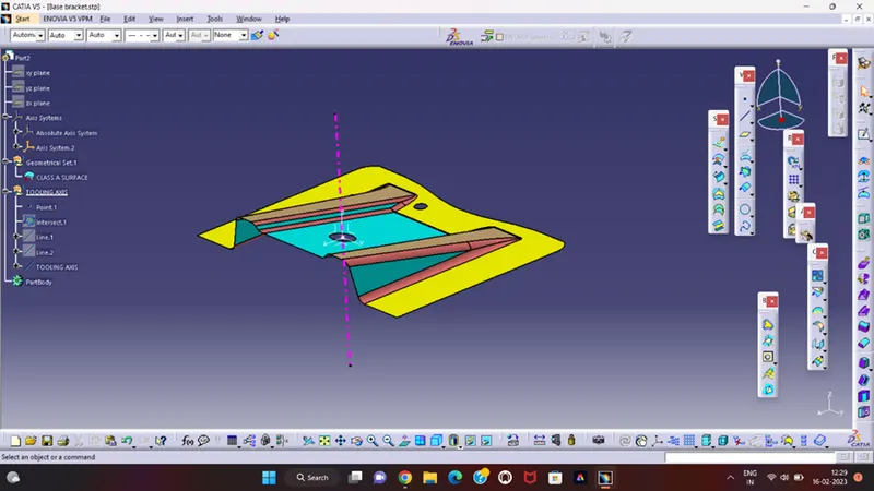
DRAFT ANALYSIS: For Draft Analysis, first go to 'Insert'>'Analysis'>'feature draft analysis'. Align the tooling axis with the compass. Click on the surface and see that the surface is within the permissible limit of the draft values. The surface should be green and in the column proper value (3deg) should be inserted.
