Project 1
Objective: Designing a wiring harness for an engine in CATIA V5 while considering industry best practices and adhering to packaging rules is a complex but crucial task. Here's a step-by-step guide on how to approach this project:
1. Understanding Requirements: Begin by thoroughly understanding the project requirements and objectives. Make sure you have all the relevant information and documentation, including engine specifications, packaging rules, and any other project-specific details.
2. Create a CATIA V5 project: set up a CATIA V5 project for this wiring harness design. This will help you keep all the design files, drawings, and documentation organized.
3. Identify key components: Identify all the key components that need to be connected by the wiring harness. This includes sensors, actuators, connectors, and any other relevant parts.
4. Layout Design: start with a preliminary layout design. Determine the general routing path for the wiring harness, considering factors like heat, vibration, and interference. Ensure that the harness is routed efficiently to avoid sharp bends and excessive lengths.
5. Select Wiring Harness Components: choose the appropriate wire types, connectors, terminals, and any protective coverings of sheathing needed. Ensure that the selected components meet industry standards and can handle the required electrical loads.
6. Routing the Harness: use CATI V5's routing tools to create the wiring harness. Follow the designated routing path while maintaining industry-specific clearance requirements. Pay attention to any clipping and clamping locations to secure the harness properly.
7. Clipping and Clapping: Design and place clips and clamps at strategic points along the routing path. These will hold the harness in place and prevent movement that could cause damage or interference.
8. Clearance and Packaging rules: Adhere to the packaging rules provided. Ensure that there is adequate clearance between the harness and other components to prevent chafing or contract that could lead to electrical faults.
9. Harness Fixing Requirements: clearly document and illustrate how the harness is fixed to the engine or surrounding structures. This should include specific mounting points and any necessary supports.
10. Harness Continuity: verify harness continuity by performing continuity checks, ensuring that all wires are connected correctly and that there are no open or short circuits.
11. Quality Assurance and Testing: Perform quality checks and testing to ensure that the wiring harness functions are intended. This may involve continuity testing, insulation resistance testing, and other electrical tests.
12. Documentation: Prepare comprehensive documentation, including drawings, schematics, and BOM(Bill of Materials). Ensure that all the details, including wire colors, wire gauge, and connector types, are clearly documented.
13. Review and Validation: Review your design with your team or relevant stakeholders to ensure it meets the project objectives and adheres to best practices.
14. Finalize Drawings: create flattened view drawings in CATIA V5 to illustrate the final design and routing of the wiring harness.
15. Implementation: collaborate with the manufacturing team to implement the design. provide guidance and support during the installation of the wiring harness.
16. Continous Improvement: Throughout the project, and after its completion, continuously seek opportunities for improvement and optimization. Feedback and lessons learned can be valuable for future projects.
By following these steps and ensuring that you meet industry best practices and packaging rules, you can design a wiring harness for the given engine that is both safe and efficient.
Routing the Wiring Harness for the Engine:
To route the wiring harness for the engine, the engine modeler will furnish dummy connectors at designated locations. The initial step involves identifying all connectors and sensor locations, with eight connectors on each side of the engine and two sensors on each side.
The routing process will leverage clips, clamps, and channels to achieve an optimized solution. Notably, there are a total of 20 sensors, including four cam-shaft sensors, that need to be electrically connected.
For fuel injectors on the engine, four-pole connectors are typically employed. In addition, there will be an interconnection connector facilitating the engine's connection to other vehicle components. This interconnection connector will utilize a 12-pole electrical connector featuring a mounting clip for secure attachment.
It is imperative that the plastic guiding channel used in this harness is constructed from a material capable of withstanding temperatures of at least 150 degrees Celsius. This ensures the durability and safety of the harness.
Furthermore, adhering to industry standards, the bend ratio for all bundled segments should be maintained at 1.4, ensuring proper flexibility and stress distribution throughout the wiring harness.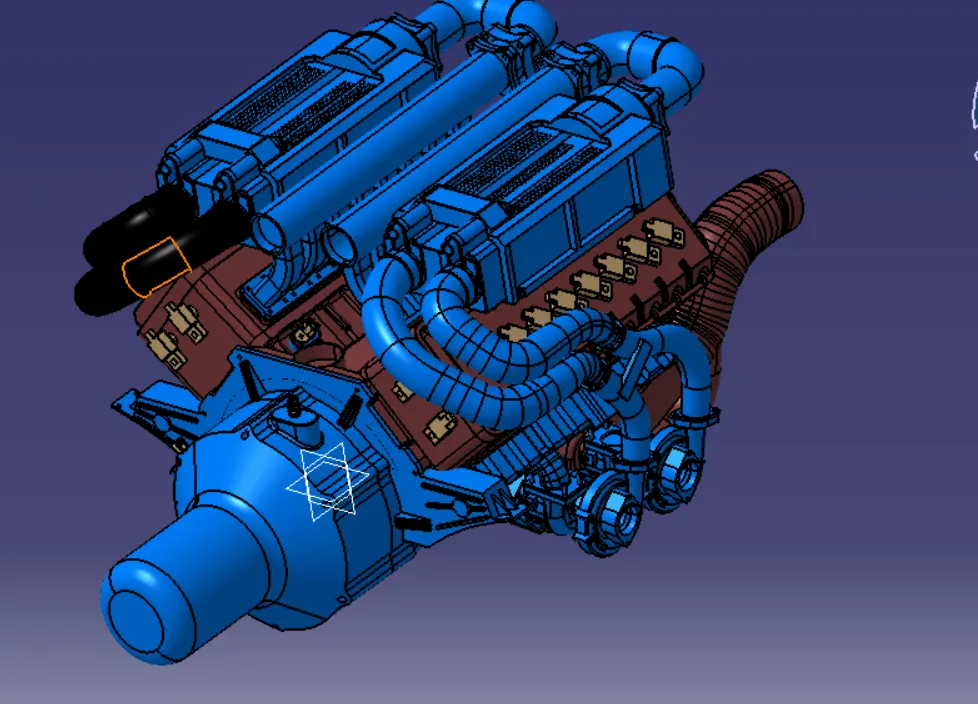
Assumptions:
1. clips and clamps will be provided based on the specific requirements of their wiring harness design.
2. Design considerations will ensure the absence of any chafing or fouling issues during the wire harness routing. Additional clips and clamps may be incorporated to prevent fouling.
3. Extra slack in the wiring harness will be included, with a recommended range of 5-10%slack to accommodate potential adjustments.
4. Routing over bolts and bolted joints will be avoided to prevent puncturing of the harness.
5. Routing over sharp edges will be avoided, and protective measures will be implemented where necessary to safeguard the harness.
6. Adhereance to specified clearance distances will be maintained to keep the harness away from heat-generating components.
7. Protective measures will be implemented as needed based on the surrounding temperature conditions.
8. Direct support for the harness on fuel lines within the engine will be avoided.
9. Plastic guiding channels may be utilized when required for routing and protecting the wiring harness.
10. Branches in the wiring harness should have a minimum length of greater than 50mm.
11. The minimum distance between two branch points in the harness will be at least 50 mm.
12. The minimum distance between a clip and a branch point in the harness will be at least 25mm.
13. Efforts will be made to minimize the use of sheet metal brackets on the engine, and available threaded bosses on the engine will be used when feasible.
14. The wiring harness design will prioritize ease of assembly and accessibility.
15. When using dummy connectors, practical positions will be defined, and bundle diameters and other placements will be specified appropriately for effective wire harness routing.
16. In cases of tight packaging areas with numerous constraints, the consideration of creating a harness channel may be explored to facilitate the efficient routing and protection of the wire harness.
Creating Context Assembly:
A context Assembly for the engine harness has been created which will work as the main assembly as shown in the above figure.
A context Assembly will contain engine assembly data for engine V16 and Engine Harness Geometrical Bundle Assembly.
If any sheet metal bracket is required then they are added in the context assembly.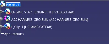
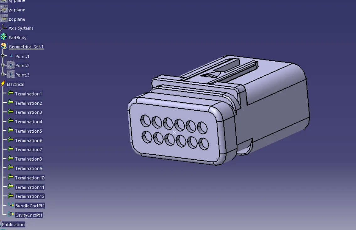
In accordance with the specified requirements, we are utilizing a 4-pole connector known as 'C-1563689'This CAD data has been sourced from te.com.
To establish the electrical definition of these connectors, it is essential to define the geometrical parameters such as the bundle connection point Electrical Part Design workbench for this downloaded connector.
DEFINING PARTS:
To establish the electrical definition of "Connectors", follow these steps:
1. Create a Geometrical set, including points at the bundle entry side, mating side, and cavity side. Additionally, generate axis systems at the mating side and cavity side, ensuring consistency across axes systems in mating parts.
2. Transition to the Electrical part design module to define the connector and clip as electrical parts.
3. Utilize the "Define Connector" command to specify the connector and the "Define Mounting Equipment" command to define the clip.
4. Further refine the definition by employing the "Double Bundle Connector Point", "Define connector Connection Point," and"Define Cavity Connection Point" commands. Choose the appropriate points, faces, and axes for the Bundle Connection point, Connector Connection point, and cavity connection point.
5. Utilize the "Define Cavity" command to establish the configuration for the clip.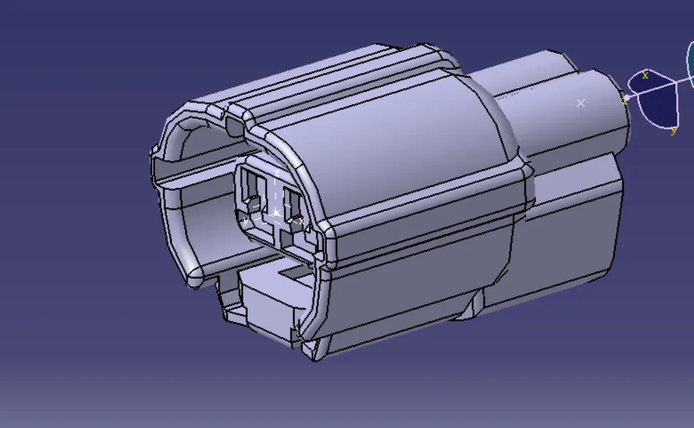
To define the "P-clamp" electrically, follow these steps:
1. In the part design module, create the necessary geometrical parameters such as points and planes required for defining the P-clamp as a support part.
2. Transition to the Electrical part design module.
3. Use the "Define Support" command and select the entry point, entry place, exit plane, and base plane for the P-clamp.
4. Given that there are two possible entries in the clamp, use the same"Define Support" command to select the appropriate point and planes to define the other points as the entry point. Ensure consistency in the definition for both entry points.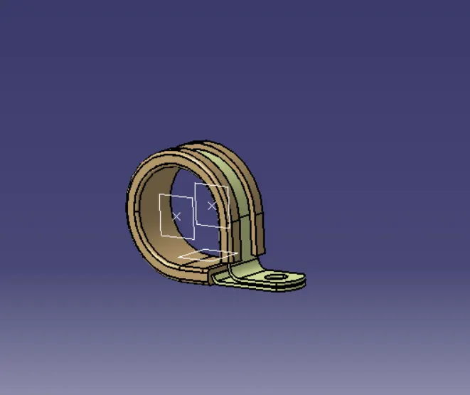
To electrically define the "Guiding Channel", follow these steps:
1. Create a Geometrical set that includes points at all eight ports, as shown in the image.
2. Create a line to represent the route for the bundle segment inside the channel. Use the externa curve option for this purpose.
3. Utilize the"Define Bundle Connection Point" command to define the bundle entry point. Choose the appropriate planes and points, and confirm by clicking "OK".This step helps establish the electrical connection for the bundle within the guiding channel.
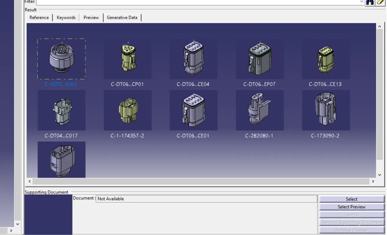
Once you've completed the electrical definitions for all components, including the"Guiding Channel", use the copy-paste function to add them to the "Engine Wiring Harness Geometrical Bundle" product. Additionally, incorporate the connectors from the catalog into the assembly, following the arrangement shown in the provided image. This ensures a comprehensive and accurately configured engine wiring harness geometrical bundle.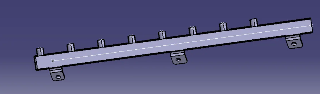
ALL THE CONNECTORS ARE ADDED TO THE CATALOG DOCUMENT
Installing the Interconnection Connector and L clip on the Engine Wiring Harness.
1. Begin by placing the L clip on the engine at the designated location. The purpose of this Lclip is to securely hold the interconnection connector in place.
2. Add the L clip metal bracket inside the context assembly, ensuring it fits snugly in the desired position.
3. Position the L clip as illustrated in the figure provided below.
4. Define the mounting clip electrically, establishing the necessary electrical connections.
5. Connect the interconnection connector and the clip to each other, ensuring a secure electrical connection.
6. Add both the connector and clip to the engine wiring harness assembly.
7. Finally, mount the interconnection connector and clip on the previously positioned L clip, ensuring a secure and stable connection between the connector and the engine wiring harness.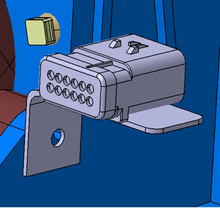
Installing P Clamps and Furr Tree Clips for Wiring Harness Clamping:
1. Begin by placing the P clamp and furr tree clips at designated locations to provide clamping positions for the wiring harness. These clips play a critical role in securing and organizing the harness.
2. Define the P clamp and furr tree clips electrically, ensuring that their electrical characteristics and connections are accurately specified.
3. Insert both the P clamp and furr tree clips into the engine wiring harness product file, integrating them into the harness assembly.
4. Position the P clamp in the designated clamping position on the engine. This ensures that the harness is securely held in place while adhering to industry-standard clamping practices.
5. Place the furr tree clip on the engine following industry-specific rules and guidelines. These clips are strategically located to secure the wiring harness, preventing any undue stress or interference.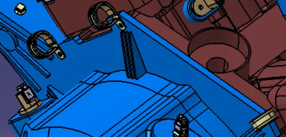
POSITIONING:
To position the connectors, channels, clips, and champs in the given Engine CAD model, follow these steps:
1. Switch to the "Assembly Design" module.
2. Utilize commands such as "Manipulation", "Snalp", "Smart Move", "Translation", or"Rotation" as demonstrated in the provided image. Apply these commands to position the components accurately.
3. Specifically, place the P-clamps and fir tree cable ties according to the routing specified in the images.
4. Position the interconnect connector on the bracket, ensuring it is correctly placed.
5. Similarly, position the guiding channel near the injectors on the cylinder head, aligning it with the specified routing.
By following these steps, you'll ensure that the connectors, channels, clips, and clamps are appropriately positioned in the Engine CAD model, adhering to the routing guidelines provided in the images.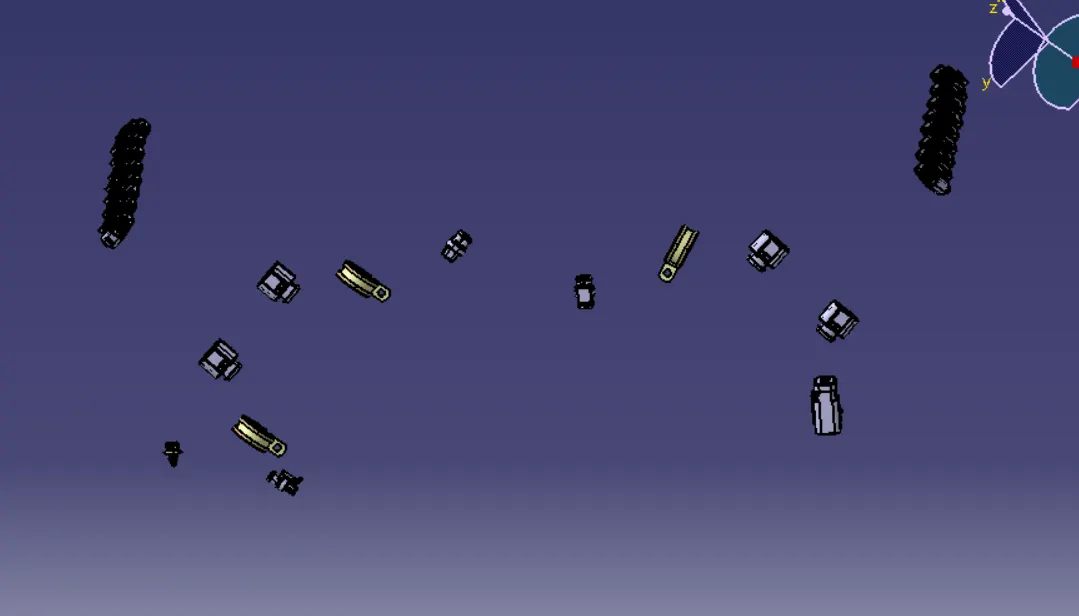
Installing Plastic Guiding Channels:
1. The engine features a total of 8 injectors, located on both the left and right sides of the engine. These guiding channels will be used to route and protect the wiring harness associated with these injectors.
2. The guiding channels are designed with an open-bottom configuration where the bottom is fixed, and the top is moveable, allowing for ease of installation and harness routing.
3. Define the guiding channels as equipment, specifying their properties and characteristics in the design.
4. Intrest the guiding channel into the geometrical bundle, ensuring it is integrated into the bundle assembly.
5. Mount the guiding channel in the required position. Ensure that it is secured in a manner that provides optimal support and protection for the writing harness.
6. Mount the top side of the guiding channel, ensuring that it is appropriately positioned and securely attached to the engine, completing the installation of the guiding channel system for the wiring harness.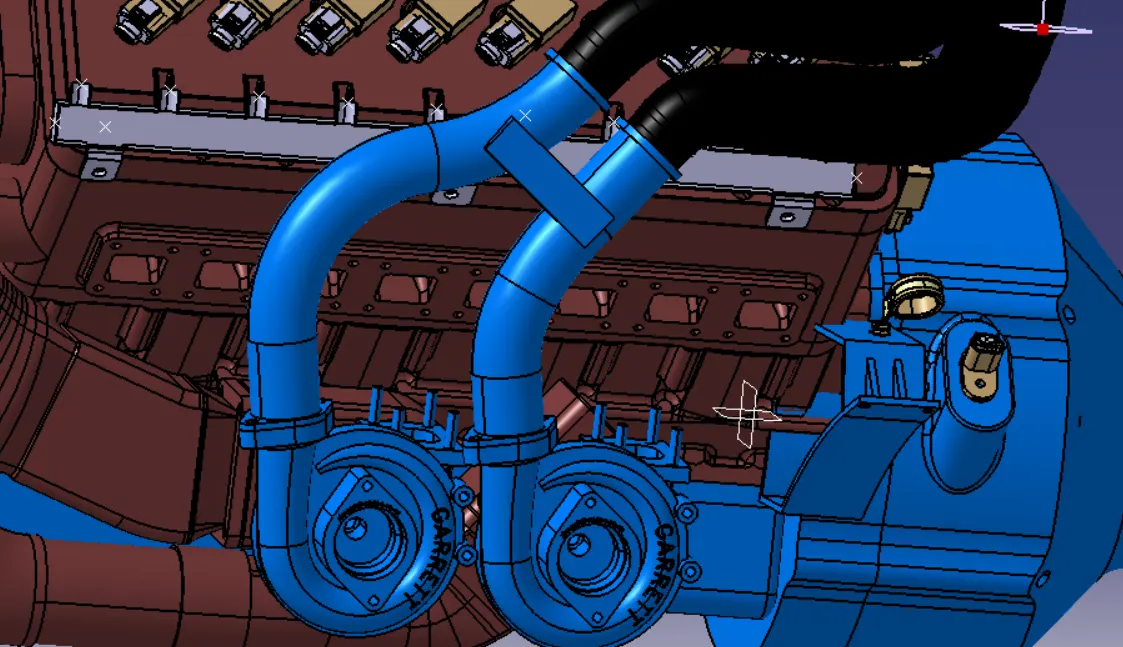
MULTI BRANCHING:
To initiate the creation of a Multi-Branchable document, follow these steps:
1. Start routing the first bundle segment by clicking on the "Branch Definition" command, as illustrated in the provided image.
2. As you activate the "Branch Definition" command, the module will automatically switch to Electrical Harness Installation mode.
This process establishes the foundation for a Multi-Branchable document, and by following the specified command, you can seamlessly transition to the Electrical Harness Installation module for further actions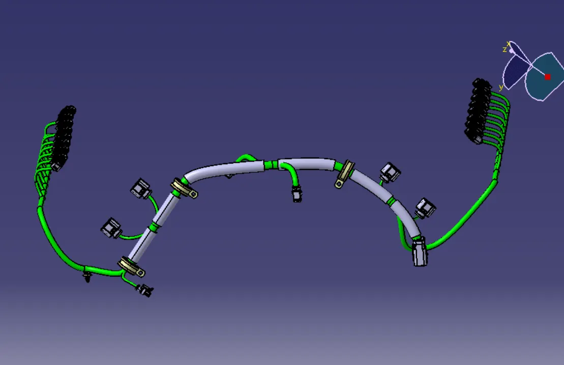
Adding Protective Covering to the Wiring Bundle:
1. To enhance the protection of the wiring bundle, it is necessary to add a protective covering. This covering safeguard the wiring from environmental factors and potential damage.
2. Create a corrugated (cot) tube designed for this purpose and add it to the catalog of available components. Ensure that the specifications and dimensions of the tube are accurately defined.
3. Within the Electrical Harness Assembly workbench, access the "protective covering" command.
4. Apply the protective covering to the wiring bundle, following the specific guidelines and configuration as depicted in the accompanying figure. This protective covering ensures the wiring remains shielded from external elements, contributing to the overall durability and reliability of the harness assembly.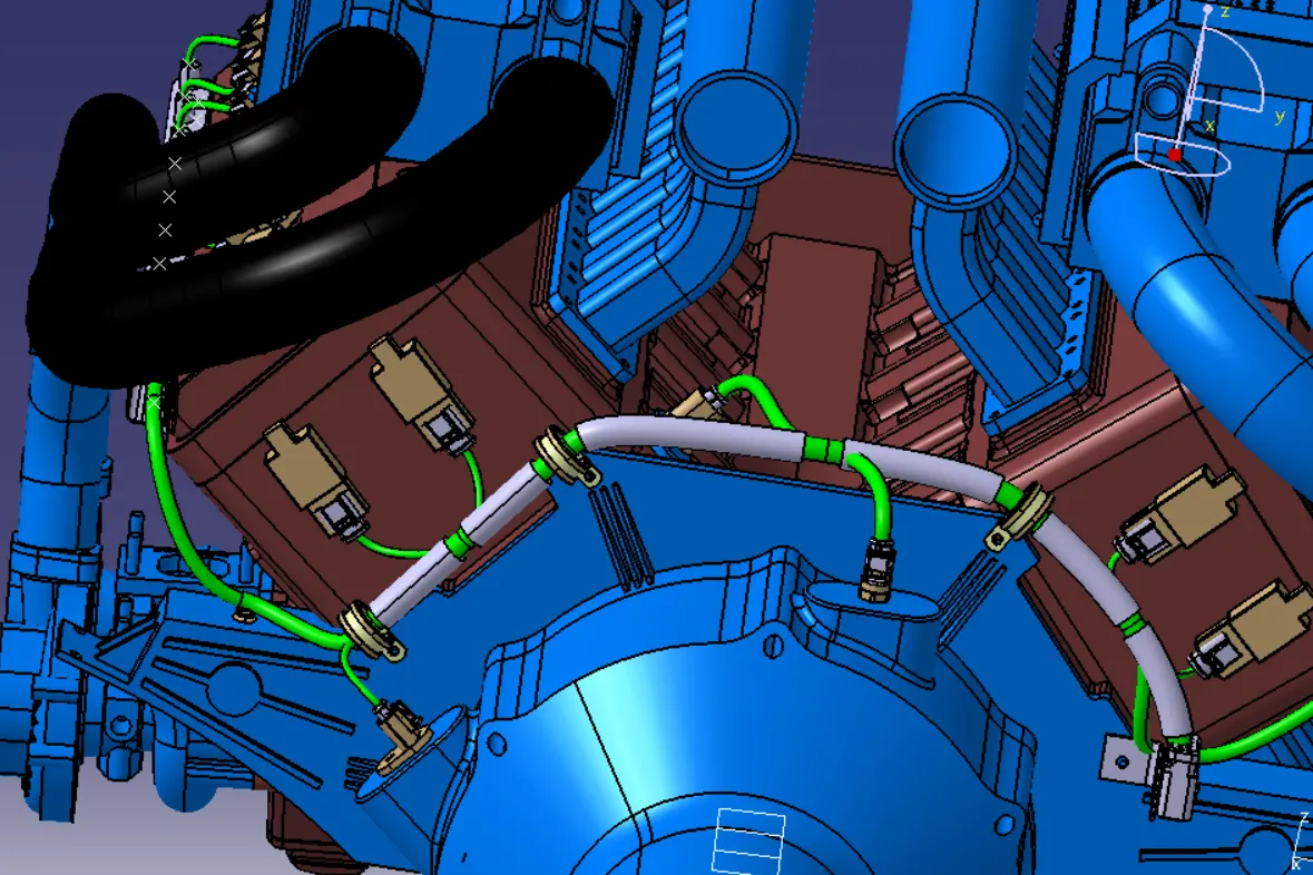
Verifying Bundle Continuity:
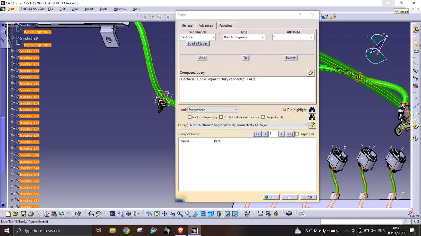
In this step, Begin by ensuring that the multi-branchable option is activated. Then, negative to Edit>search>Advanced>Workbench-Electrical>Type-Bundle Segment >Attribute-Fully connected.
By selecting the 'True' option, all connected bundle segments will be displayed, while opting for 'False' will reveal all non-connected bundle segments.
For this specific case, we have chosen the 'True' option and initiated the search for results. As a result, all the bundle segments are highlighted, confirming that they are electrically connected, as illustrated in the figure below.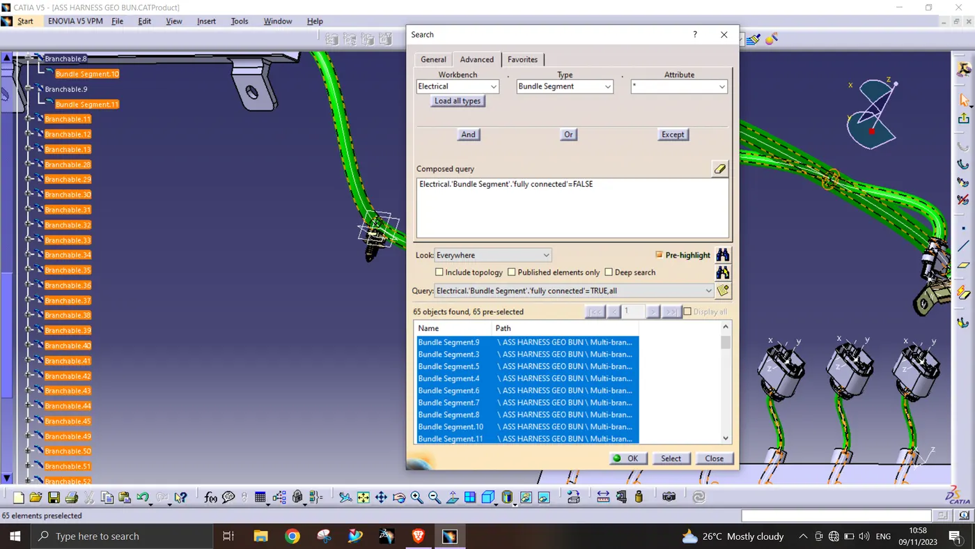
Flattening the Wiring Harness Bundle:
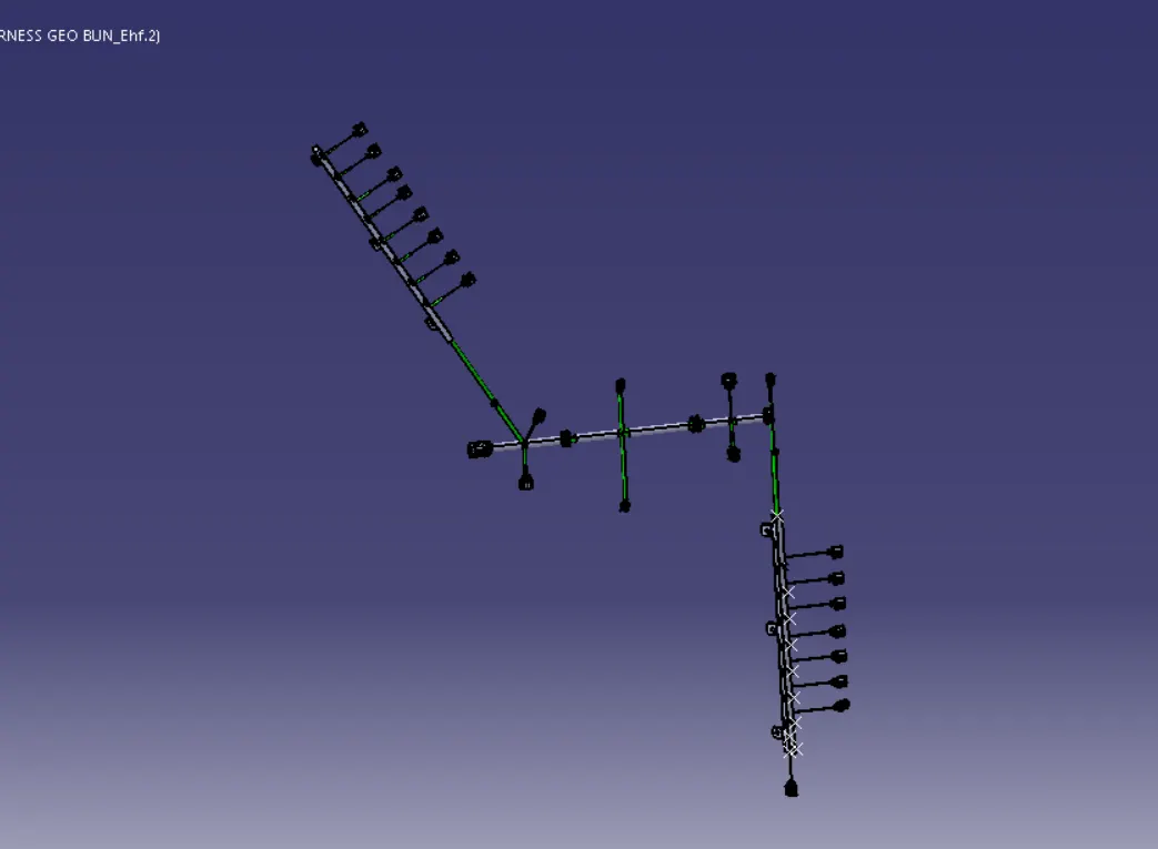
1. To flatten the wiring harness bundle, initiate by creating a new product file to accommodate the flattened harness configuration.
2. Switch to the Electrical Harness Flattening workbench within the design software.
3. Configure the harness flattening parameters in line with the specifications depicted in the provided figure. These parameters govern the process of achieving the flattened view of the wiring harness
4. After setting the parameters, proceed by clicking the"Extract" command. This action will enable the software to generate the flattened view of the wiring harness.
5. In the next step, Select the engine wiring harness product file to be flattened. The software will utilize the defined parameters to create the flattened representation of the wiring harness within the new product life.
DRAFTING:
To create the"Engine Wiring Harness Flattening Drawing" follow these steps:
1. Open a new CAD Drawing file and name it "Engine Wiring Harness Flattening Drawing".
2. Use the "Font View" command to set the view orientation.
3. Select the required plane in the Flattened Harness Assembly to pull the flattened view into the drawing sheet.
4. Go to the properties of the drawing.
5. Enable the "3D Wireframe" option for a clearer representation.
6. Also, enable"3D colors" for a more detailed visualization.
7. Click "OK" to apply the changes.
8. Save the drawing file with the desired name.
Following these steps will result in the creation of the"Engine Wiring Harness Flattening Drawing" with the specified view and display settings.
adding connectors to the engine wiring harness. Place these connectors strategically on the fuel injectors, neutral position sensor, camshaft sensors, and vehicle speed sensor.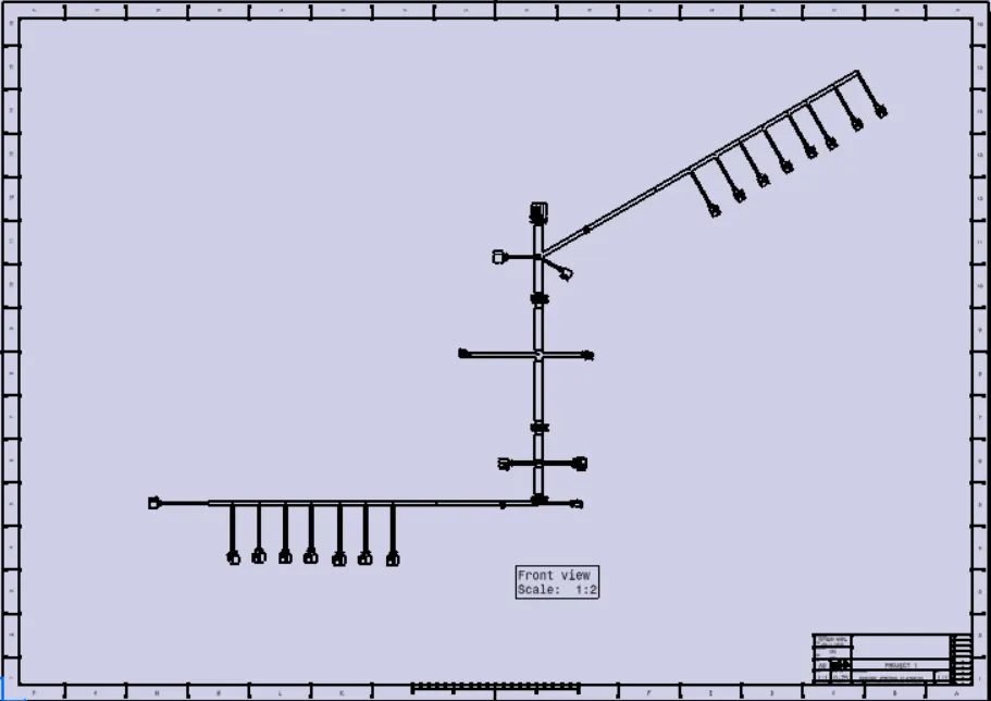
OUTCOME: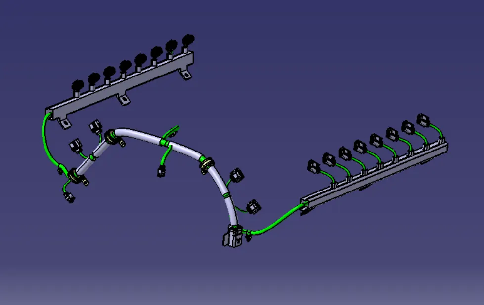
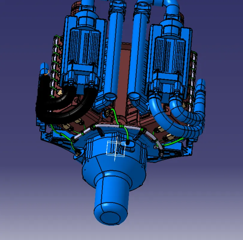
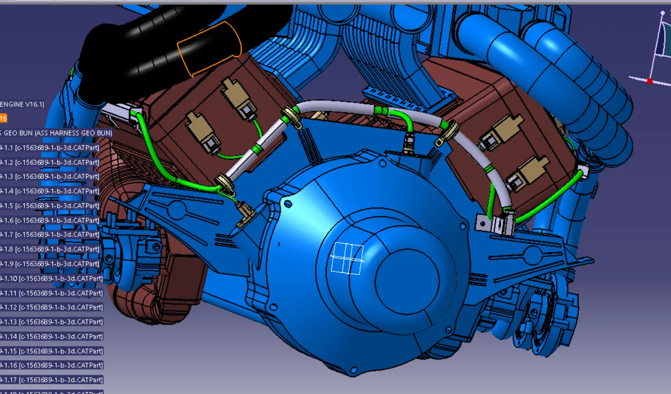
CONCLUSION:
In summary, the wiring harness assignment was executed in CATIA V5 with a focus on applying packaging rules and industry best practices. Leveraging connector 3D data, the design adheres to standards and demonstrates attention to details like clearance, clipping/clamping, and continuity. The use of CATIA tools ensures efficiency in routing, while the flattened view drawing and application of 3D wireframes and colors enhance clarity. The inclusion of protection coverings adds durability. The submission of comprehensive reports underscores transparency and adherence to design principles.
NOTE:
I cannot able to upload my design file so I have provided a Google Drive link where you can view my answers
https://drive.google.com/drive/folders/1H9AKPh7tNGlf1hdez-BEIRdmZD_gsWdW?usp=drive_link
https://drive.google.com/drive/folders/1H9AKPh7tNGlf1hdez-BEIRdmZD_gsWdW?usp=drive_link