Project 1
Project 1: Development of a Complete Wiring Harness Assembly for a V16 Engine
Statement of assignment:
Route the Wiring harness on Given Engine and Prepare flattened view drawing in CATIA V5. Application of all Packaging rules, Industry best practices studied in this course shall be demonstrated in design. Apply Protection coverings as required.
Available connector 3D data can be used, or you can download the connectors from www.te.com
Prepare & Submit all necessary reports like clearance, Clipping/Clamping selection, Harness fixing requirements, Harness continuity, and Assumptions if any along with CATIA 3D data.
Engine Wiring Harness Routing
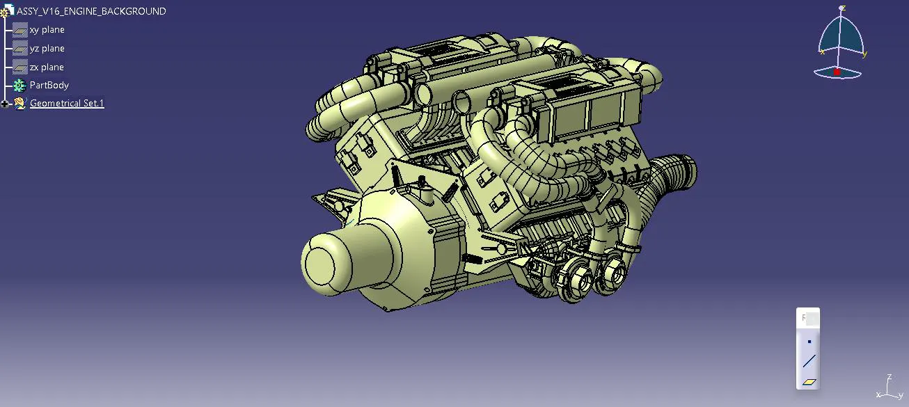
The V16 engine CAD data is seen in the image above. The wire harness for the following engine-attached electrical components is routed here.
- Each of the 16-cylinder engines has a fuel injector.
- There are four camshaft sensors on each engine block.
- Engine coolant sensor between the two blocks in the middle of the engine.
- Engine oil temperature and pressure sensors are installed on both cylinder blocks' oil sumps.
- Sensors that detect the gearbox assembly's neutral position and gauge vehicle speed.
- An interconnection connector to link the vehicles and the engine's harness systems.
- It is necessary to mount the wire harness and manage its routing to ensure suitable wiring harness packaging. Additionally, clearance management and manufacturability are addressed.
- P-clamps to offer effective routing clearance management and positive clamping.
- Corrugated tubes are used to shield the wiring harness from potentially dangerous substances and temperatures.
- Mounting clips for mounting the connectors
- Guiding channels provide thermal protection in high-temperature zones.
Next, make an assembly wire harness context new product in the assembly workbench. The wire harness electrical bundle and geometrical bundle are constructed inside of this product file at the top level. Given that this context component now has V16 engine CAD data.
All of the harness parts, such as connectors, clips, grommets, and actual physical bundle segments and branches, are included in the geometric bundle. Electrical definitions should be given to each component.
Placement of Connectors
- Switch to the “Assembly Design” workbench, and start placing the connectors at the proper location using the snapping features and compass
- Place the 4-pole Connectors at the 16 Fuel Injector Sensors
- Place the 4-pole Connectors at the 4 Camshaft Sensors
- Place 2-pole Connectors on the Coolant Temperature and Vehicle Speed Measurement Sensors.
- Place Connector No. 2 on the Neutral Sensor.
- Place the L-sheet Bracket and the Interconnection Connector in the Desired Suitable Position to Assist in the Wiring Harness and Routing
- Place the P-clamps on the Desired Suitable Position to Assist in the Wiring Harness and Routing.
- Place Fir Tree Clips on the Desired Suitable Positions to Assist in the Wiring Harness and Routing
Harness Routing and Packaging
- Include all of the electrically defined components in the geometric bundle. Place the parts in a way that allows the harness to be routed through them.
- Use the “Geometrical Bundle” command on the electrical harness assembly workbench to electrically specify the geometrical bundle product file.
- The geometric bundle contains the accessible connectors that are correctly mounted on the fuel injectors, camshaft sensors, engine coolant sensors, and camshaft sensors. A manipulation tool is used to position the connectors.
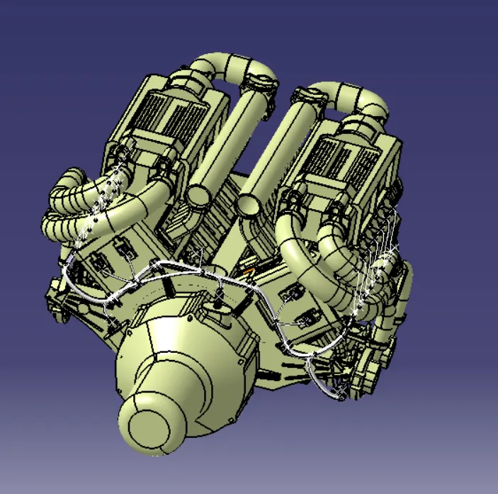
- The interconnection connector is where the bundle routing begins, followed by the P-clamps and guiding channels. Add branch points to direct the wire harness from the main branch to different connectors.
- Choose the external curve option, then click on the line that has been drawn in the guiding channel to route the wiring harness through it. After that, add branch points to the wiring harness to direct it to the connectors from the guiding channel. To prevent tension on the wire, the bundle section is given the necessary bend radius and slack.
Design Criteria to Follow for Routing the Wiring Harness
- The routing of the wiring harness took into account variables including ease of manufacturing, accessibility, convenience of equipment attachment and maintenance, and ease of equipment removal.
- The wiring harness should be laid out so that it is simple to install on a vehicle.
- The wiring harness should be routed and maintained away from sharp surfaces such as panel edges and corners.
- When installing the harness, avoid routing and clipping in the operator's blind zone.
- Verify that the route satisfies the conditions for clearance with the various adjacent parts.
- When routing, each branch must have adequate slack to prevent further strain on the wire and terminal crimping joints, but the extra slack must not interfere with neighboring components or reduce the desired clearance requirements.
- Enough clamps should be available to guarantee the wiring harness's safety and positive clearance with the environment.
- If using clamps to satisfy the clearances in crucial sections is challenging, then the use of plastic guiding channels is recommended.
- The minimum branch length should be 50mm.
- There should be a minimum of 25mm between the clip and the closest branch point.
- There should be a minimum of 50mm between two breakouts.
- Check to see that harness protection is offered by the local temperature, manufacturing potential, and expected reliability.
- A minimum bend radius of 1.8 is required
Wiring Harness Flattening
To flatten the wiring harness, create a new product file and save it with the desired name in the same folder as the wiring harness. Then, select “Harness Flattening Parameters” and define harness flattening parameters on the “Electrical Harness Flattening” workbench. Make sure to select “Double line” for the bundle segment, and “Double line” for the protective covering when defining the harness flattening parameters before producing the flattened view.
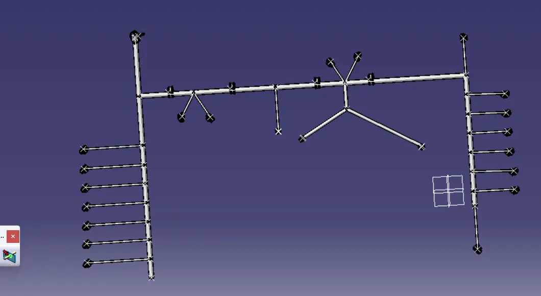
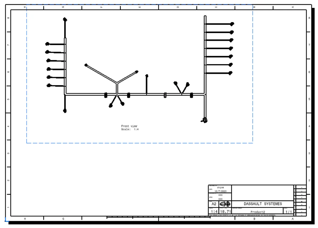
Drawing of the Flattened Wiring Harness
To generate a drawing of the harness, open a new drawing file, select the command “Front View”, then go to the flattened harness window and select an appropriate face. Right-click the drawing sheet and select properties. In the view tab, select "3D wireframe" and "is always visible" in the dress-up settings to make the bundle segments visible.