Project 1
OBJECTIVE:
Creation of Mould for a table fan outer casing using SolidWorks.
INTRODUCTION:
The injection moulding process involves heating & injecting plastic material under pressure into a closed metal mould tool. The molten plastic cools & hardens into the shape inside the mould tool, which then opens to allow the mouldings to be ejected or removed for inspection, delivery, or secondary operations.
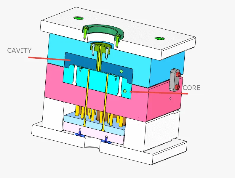
Injection moulding is a manufacturing process that allows for parts to be produced in large volumes. It works by injecting molten materials into a mould. It is typically used as a mass production process to manufacture thousands of identical items. Injection moulding materials include metals, glasses, elastomers, and confections, although it is most commonly used with thermoplastic and thermosetting polymers.
WORKING:
The first stage of injection moulding is to create the mould itself. Most moulds are made from metal, usually aluminium or steel, and precision machined to match the features of the product they are to produce.
Once the mould has been created by the mould-maker, the material for the part is fed into a heated barrel and mixed using a helical-shaped screw. Heating bands melt the material in the barrel and the molten metal or molten plastic material is then fed into the mould cavity where it cools and hardens, matching the shape of the mould. The cooling time can be reduced through the use of cooling lines that circulate water or oil from an external temperature controller. Mould tools are mounted on plate moulds, which open once the material has solidified so that ejector pins can eject the part from the mould.
METHODOLOGY:
The injection moulding process requires careful design, including the shape and features of the part, the materials for the part and the mould, and the properties of the moulding machine. As a result, there are various considerations that need to be taken into account when injection moulding.
PROCEDURE
STEP-1: Deciding the tooling direction
- Selected the tooling direction which leads to minimum udercuts
- done draft analysis to check adequate drafts in the model
- core
- cavity
STEP-2: Scaling the model
Increased the model size by 0.6% to account shrinkage because ABS material shrinkage % is 0.6%
calculation
(0.6/100)+1 = 1.006
so 1.006 is the scaling value
STEP-3: Creating parting line
It is a core & cavity separating line or core and cavity meets at this line
STEP-4: Creating sutt-off surface
To close the holes and to create the core cavity surfaces
STEP-5: Creating the parting surfce
Surface which separates the core and cavity into 2 blocks in a mould
STEP-6: Creating core and cavity surfaces
Merge the parting surface with core and cavity surfaces
core surface
cavity surface
STEP-7: Creating core and cavity blocks
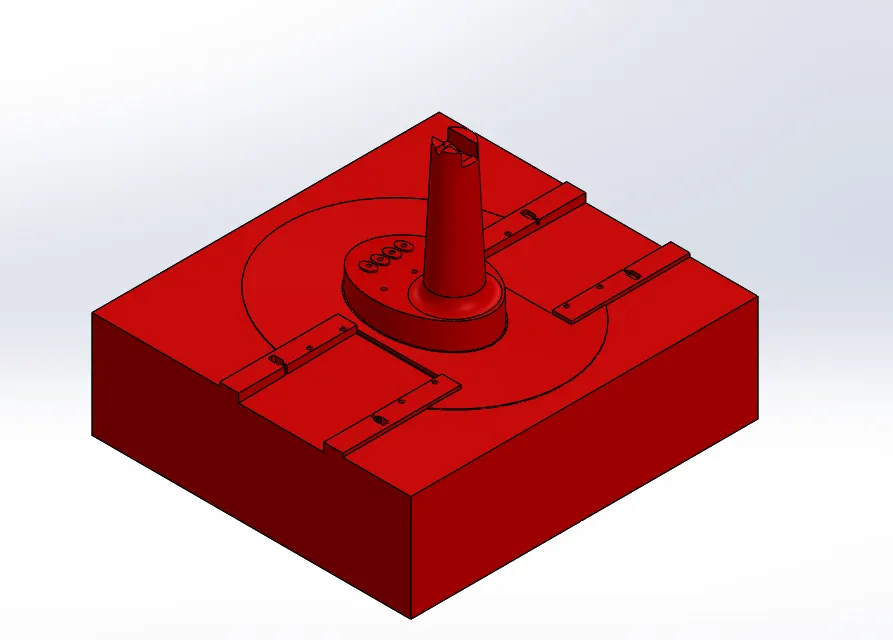
CORE
Edited the core block to match the slider block.
Created guide rails in core block.
Make a cut in the core block for bolts.
CAVITY
- Edited the cavity block to match the slider block.
- Edited cavity block as per rib rails.
- Edited cavity as per slider cuts.
- edited as per washers and gave 1mm relief.
SLIDER
Created slider block in such a way that it should not intersect with the component,gave suitable gap allowance
Created the wedge to properly interlock with cavity.
Given suitable fillets
WASHERS AND BOLT
EJECOR PINS
Ejector pins are created for the part to be pushed out from the core when the part has cooled down.
DIFFERENT VIEWS OF THE MODEL
- ISOMETRIC VEIW
- CORE WITH SLIDERS
<>></>
<>>