Project 1
Aim: Route the engine harness for V16 engine and apply the packaging rules.
Wiring harness routing principles for a V16 engine involve guidelines to ensure that the electrical wires and connectors are arranged and secured correctly within the engine compartment. The key principles include ensuring easy accessibility for maintenance, protecting against heat and vibrations, separating different electrical circuits, securely fastening the harness using appropriate clips and brackets, avoiding contact with sharp edges and moisture, shielding sensitive wires from interference, allowing flexibility for engine movement, incorporating service loops for maintenance convenience, and documenting the harness layout for future reference. These principles collectively ensure the safety, reliability, and efficient functioning of the electrical system in the intricate and high-performance setup of a V16 engine.
Step 1: Study of Engine CAD data
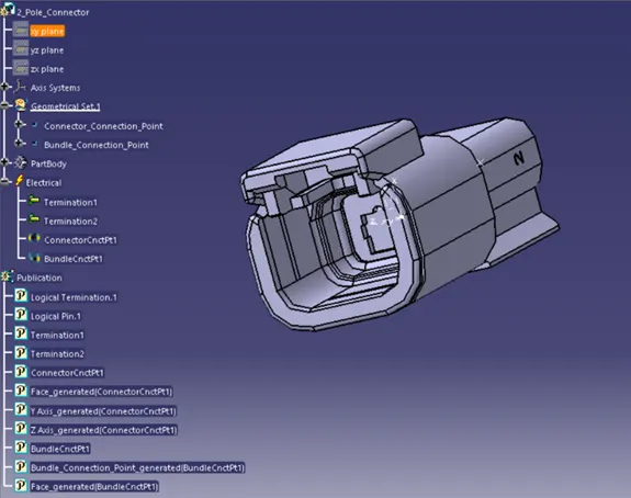
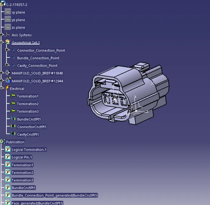
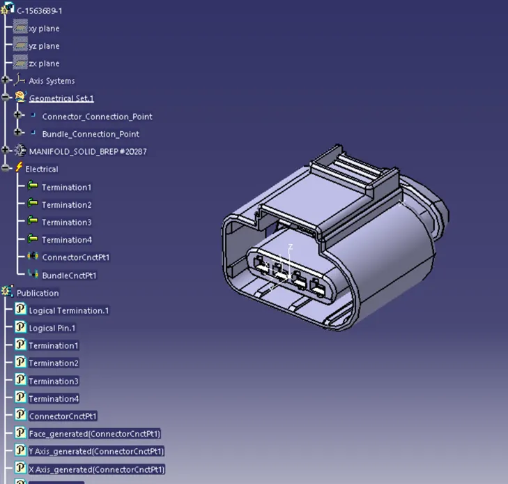
In the Engine assembly CAD data, several electrical components need to be identified and appropriately placed. The engine has a V-shaped arrangement with 8 cylinders on each cylinder block, requiring 4-pole connectors for the 8 injectors on each cylinder head. These injector connectors are closely situated, necessitating a channel for harness routing and protection. Additionally, there are 2 camshafts per cylinder block, totalling 4 camshaft sensors, each requiring 4-pole connectors. The engine coolant temperature sensor is located at the center of the cylinder block, necessitating a 3-pole connector. On the transmission case, there's a vehicle speed measuring sensor on one side, requiring a 3-pole connector, and a neutral position of transmission detecting sensor, which needs a 2-pole connector. Proper identification and placement of these electrical components are crucial for the engine's functionality and overall performance. Various features of the engine assembly such as holes accommodating the bolts can be used to incorporate suitable clips and clamps as washers to aid in an efficient routing. Also, suitable contours can be created where required in coordination with the engine CAD team by making some changes in the design.
Step 2: Defining the wiring harness components as electrical
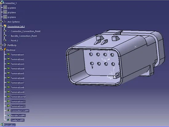
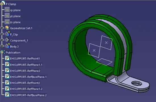
The components used for the wiring harness assembly such as the various connectors, clips, and channels need to be defined as electrical for them to be used for bundle creation between them.
<!-- [if !supportLists]-->1. <!--[endif]-->2-Pole Connector:
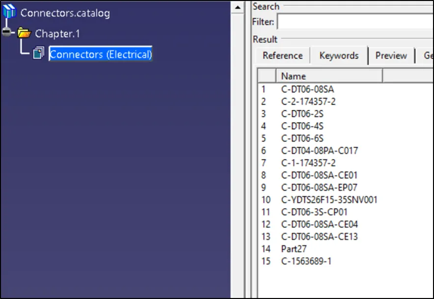
<!-- [if !supportLists]-->2. <!--[endif]-->3-Pole Connector: [C-2-174357-2]
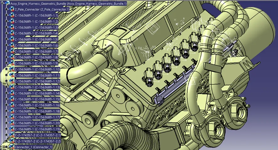
<!-- [if !supportLists]-->3. <!--[endif]-->4-Pole Connector: [C-1563689-1]
<!-- [if !supportLists]-->4. <!--[endif]-->Interconnection Connector:
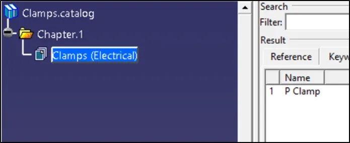
<!-- [if !supportLists]-->5. <!--[endif]-->P Clamp
<!-- [if !supportLists]-->6. <!--[endif]-->Guiding Channel Assembly:
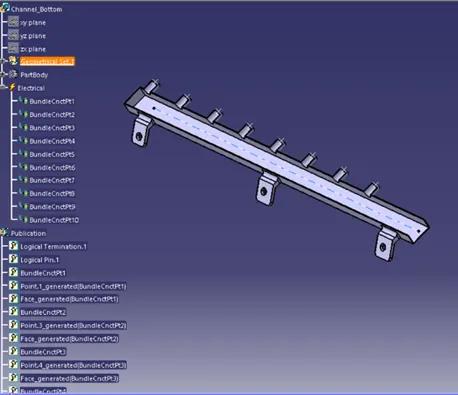
The guiding channel assembly consists of a channel top and channel bottom part. Here, only the channel bottom part is defined as electrical with features such as the bundle entry point and bundle tracing line inside the channel. The bundle entry points have to be defined at each of the branching channels. Then the channel top and the channel bottom are included into a product assembly.
<!-- [if !supportLists]-->7. <!--[endif]-->Fir Tree Clip
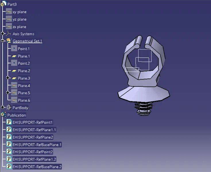
After defining all the components of the harness assembly, they are stored in a suitable catalogue.
<!-- [if !supportLists]-->a) <!--[endif]-->Connector Catalogue
<!-- [if !supportLists]-->b) <!--[endif]-->Clamps Catalogue
Step 3: Engine Harness Context Assembly creation
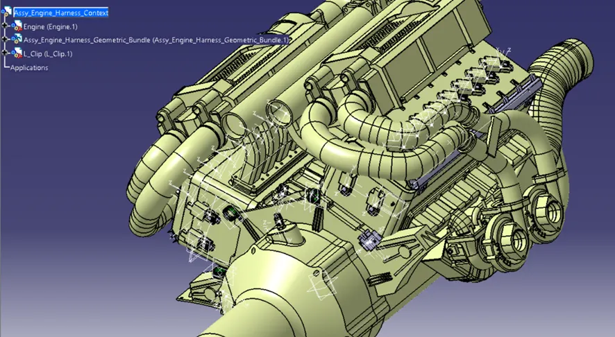
To start with the harness routing, we first need to create an Engine Harness context assembly into which the Engine product CAD data and the Geometrical Bundle Assembly product are included. The engine acts as an external support for the bundle creation and thus it in itself won’t be a part of the bundle assembly. The bundle assembly includes all the components such as the connectors, clips, clamps, guiding channels etc. Thus, all the required components are included into the ‘Geometric Bundle Assembly’ product file and are placed at their intended positions with respect to the engine assembly CAD data using various manipulation tools.
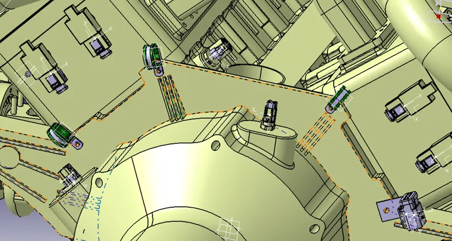
Step 4: Harness bundle Routing
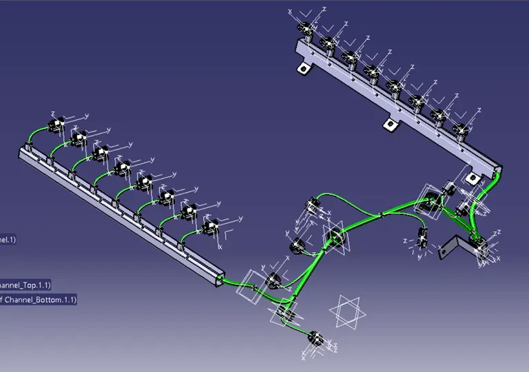
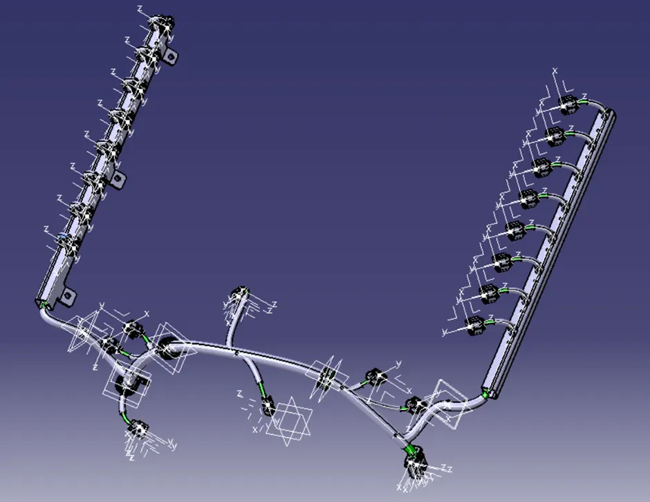
To start creating a wiring harness bundle, activate the Geometric Bundle assembly product file and electrify it using the ‘Geometrical Bundle’ command in the ‘Electrical Harness Assembly’ workbench. Then start the routing from the interconnection connector and create the main engine harness bundle around the collar of the transmission case of the engine. Then suitable branch points are created and branches are added to the bundle connecting various connectors with the help of clips and guiding channels.
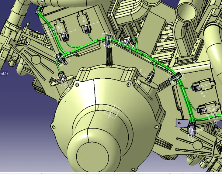
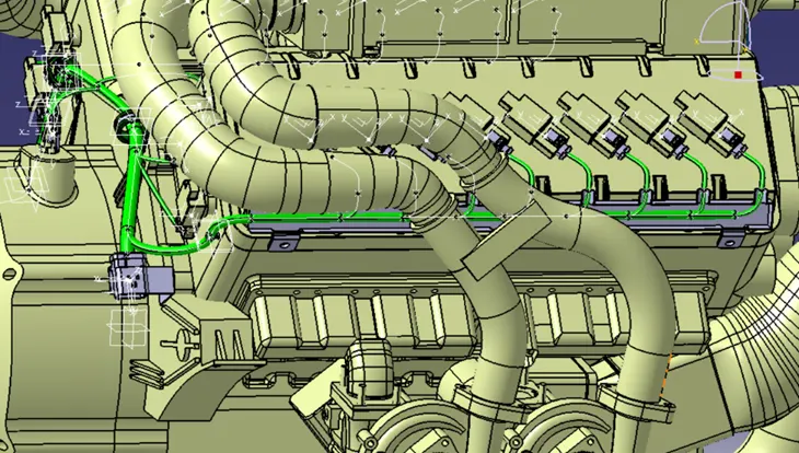
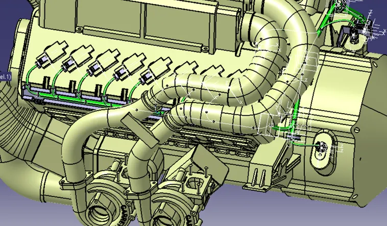
Step 5: Apply Protection coverings
Step 6: Check for Harness Continuity
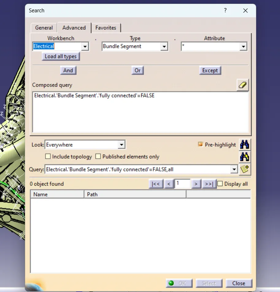
To check for bundle continuity, got to edit>search. Then in the window popup that appears select the ‘Electrical’ workbench and ‘Bundle Segment’ type. Then select the ‘fully connected’ attribute with the condition as ‘FALSE’. Then click on search. So, as the attribute is selected as ‘False’ and the result will only appear if any part of the bundle segment is disconnected. So, from the results, it is clear that the entire wiring harness bundle segment is fully connected and there is no discontinuity observed.
Step 7: Prepare Bundle Flattening
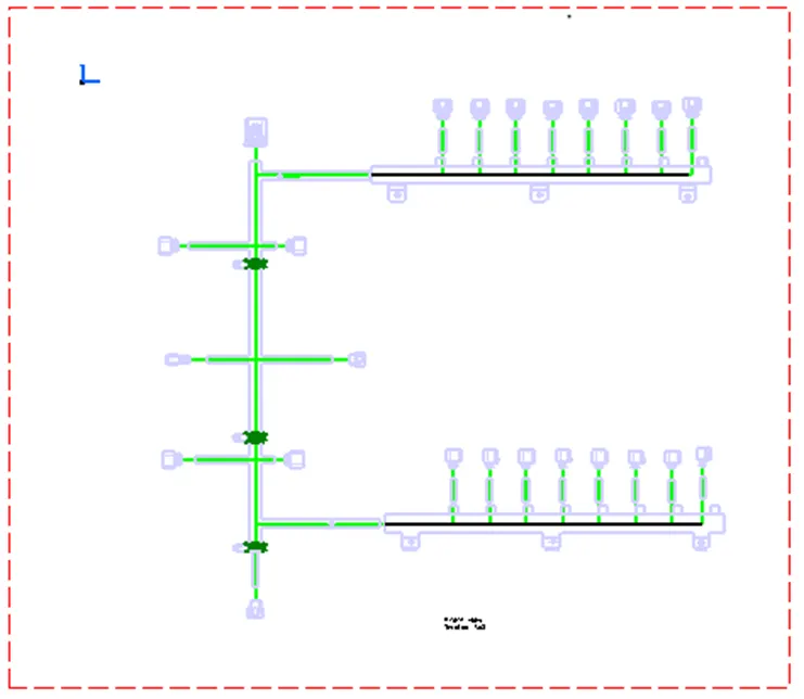
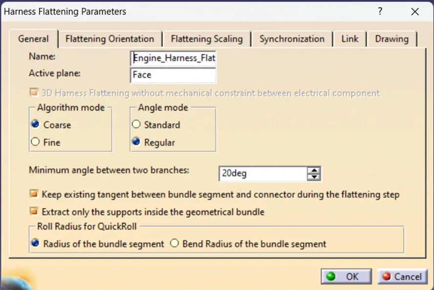
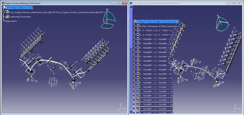
Begin the process of bundle flattening for the wiring harness routing assembly by initiating a new product file and ensuring it's saved in the same location as the 3D Harness assembly. Then, access the 'Electrical Harness Flattening' workbench and configure the harness flattening parameters to match the requirements of the current project.
<!-- [if !supportLists]-->1. <!--[endif]-->Extract 3D Harness
<!-- [if !supportLists]-->2. <!--[endif]-->Flatten and rearrange the bundle
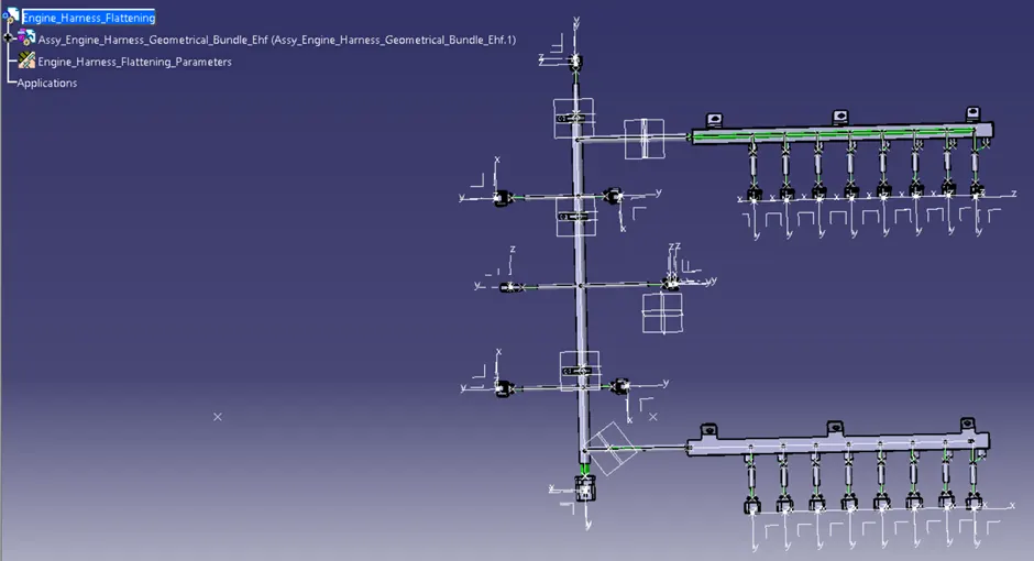
<!-- [if !supportLists]-->3. <!--[endif]-->2D Drawing