Project 1
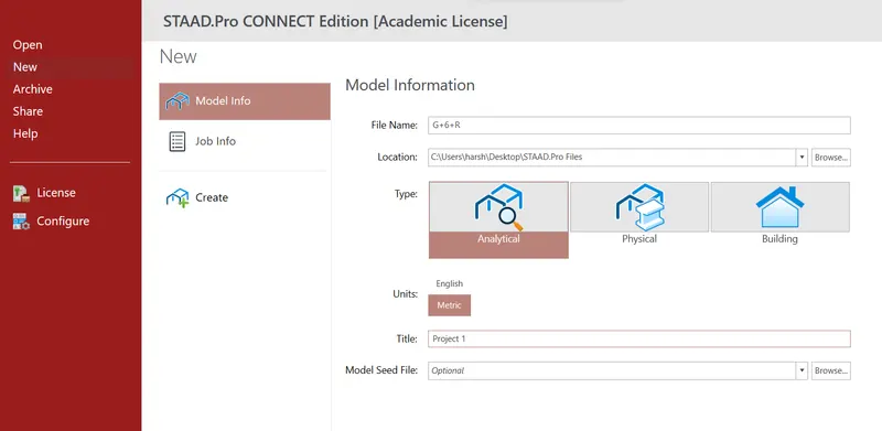
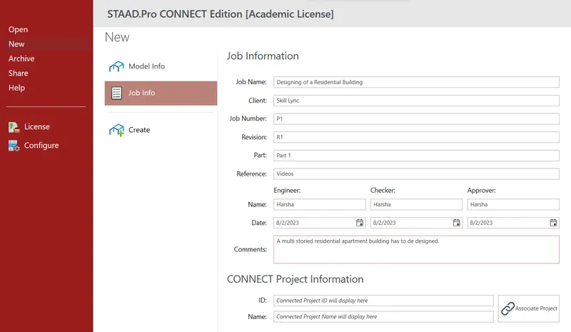
Initially,we open the Staad.Pro software.We then go to New>Model Info and give the required details and select the Analytical Type and Metric Units.
In the Job Info,we give the further details.
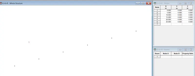
Then,the workspace gets opened.
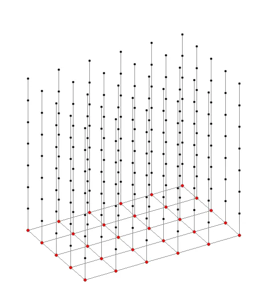
Where intially form the nodes for one line.
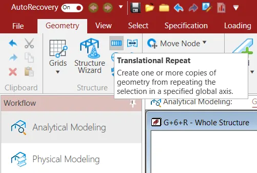
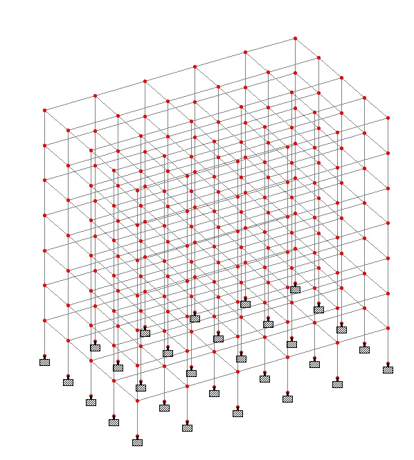
We use the option of Translational Repeat available in Geometry Tab to copy the nodes to different positions.
Thus,we form a layer of nodes.
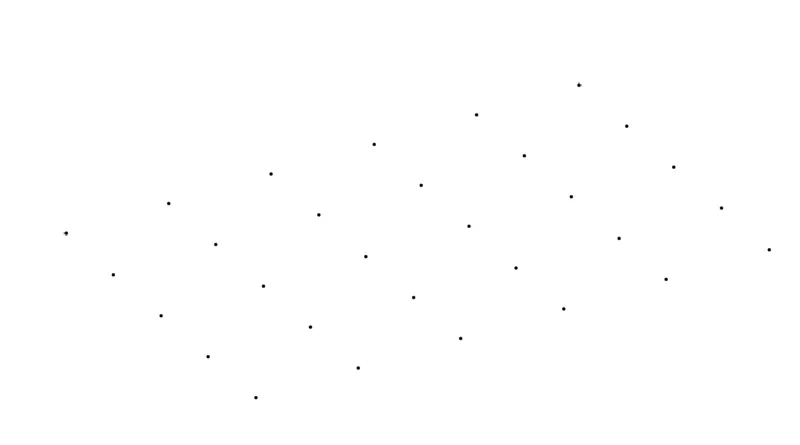
We then copy the nodes to higher positions along with linking the nodes.
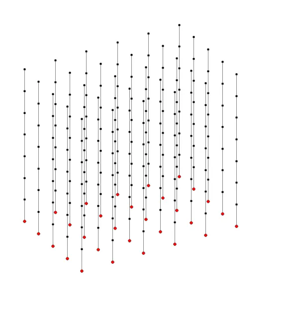
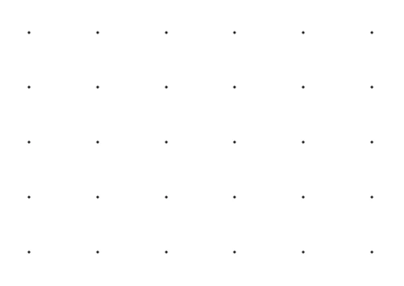
We then go to the Top View in the View Tab.
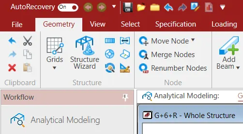
We then use the option of Add Beam in the Geometry Tab to create the beams.
So,we form the beams as shown.
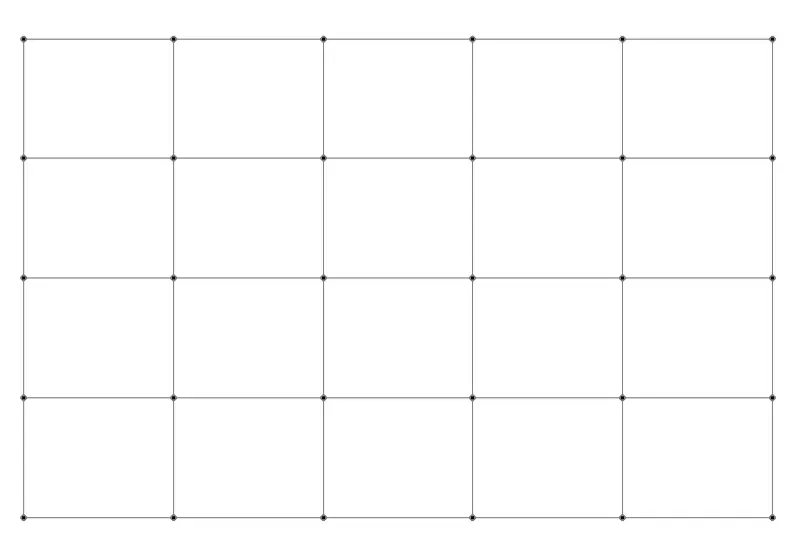
The beams formed will be available for one layer,where we will be copying those to higher positions as stories using the Beam Cursor.
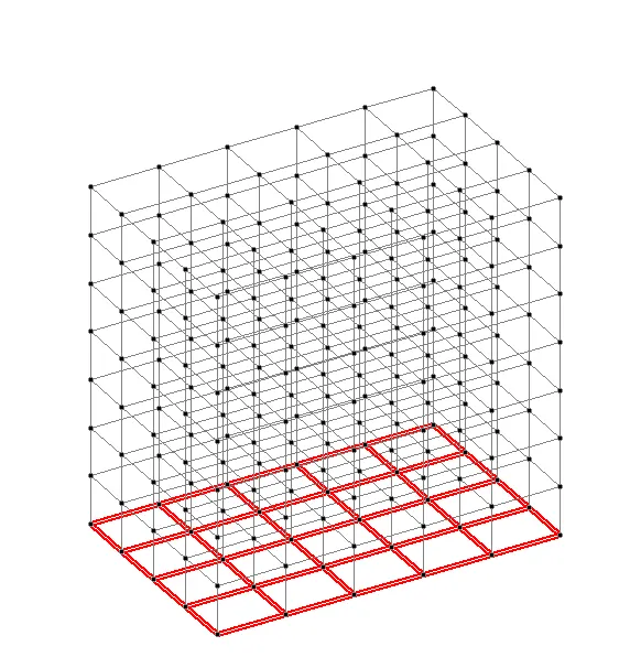
And we even remove the beams formed at the bottom which are not required.
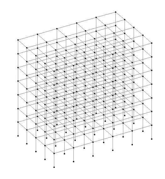
After the model creation,we form the sections for the beams and columns.
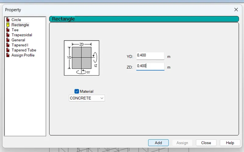
We then go to Properties Tab and we use the option of Define to form the new sections.
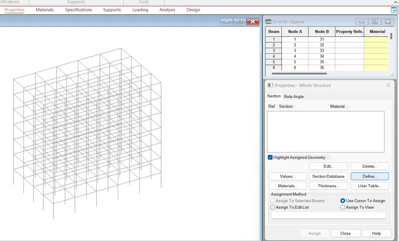
Then in the resultant tab,we select the Shape and Material and we even provide the dimensions of the section.
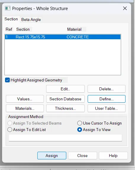
The resultant section is visible in the Properties-Whole Structure Tab.
Where we then select it and then using the option of Assign To View to set it to the model created.
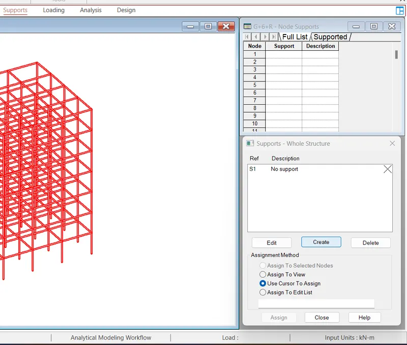
The we go to Supports Tab,using Create option,we create a support.
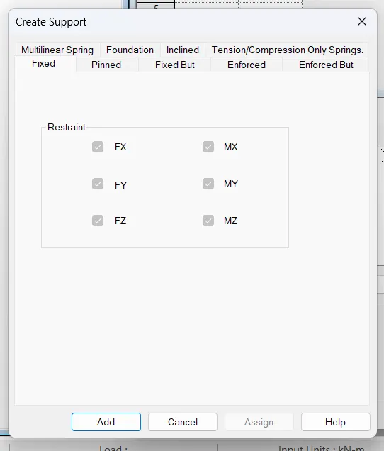
Where we Add a Fixed Support.
Where we select the required nodes using the Nodes Cursor and then we assign the supports to those.
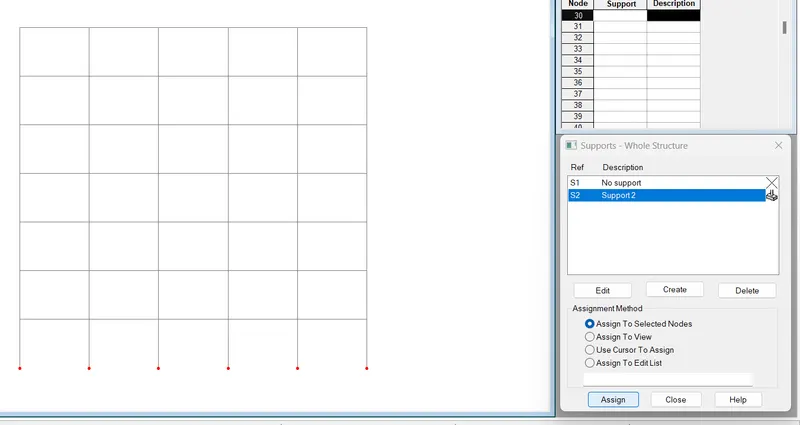
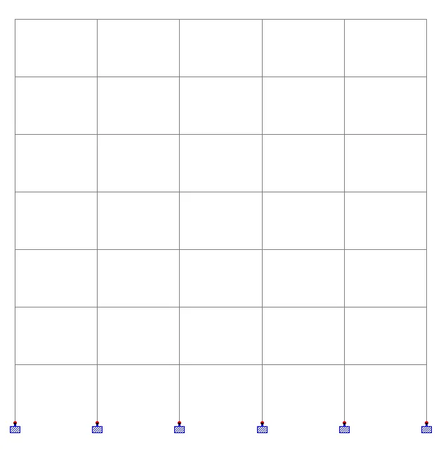
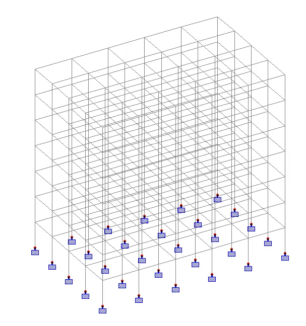
Then we go to Loading Tab,where we initially add the Load Cases.
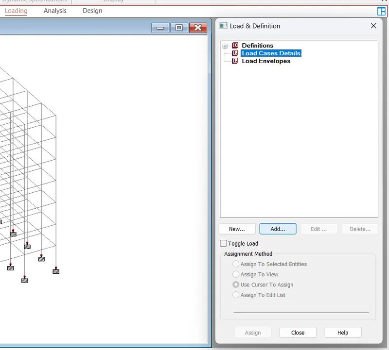
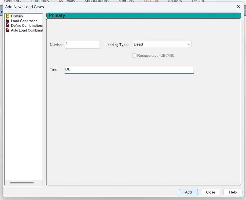
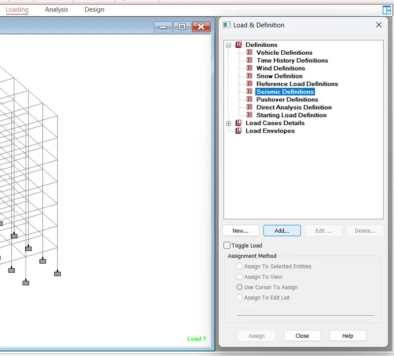
We even require the definition for the Seismic Loads and for Wind Loads.
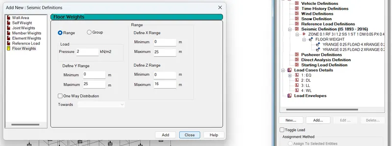
So,we go with Loading Tab>Load & Defintion>Definitions>Seismic Definitions>Add...
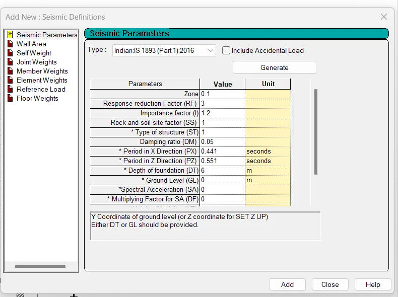
Where we give the required seismic parameters.
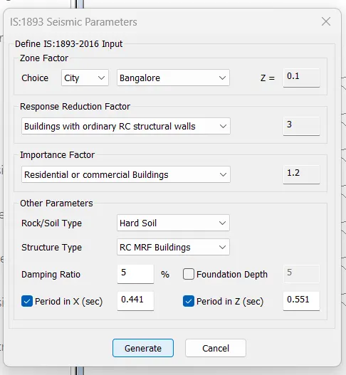
We even give the loads to be considered under the seismic loads.
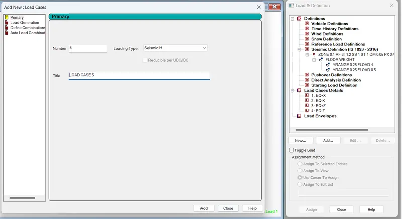
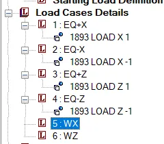
Where 4 cases are formed for 4 different directions of the EQ loads.
Similarily,we even define the Wind Load.
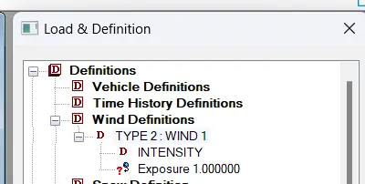
Where along with adding the Wind Intensity,we even add the Exposure Factor.
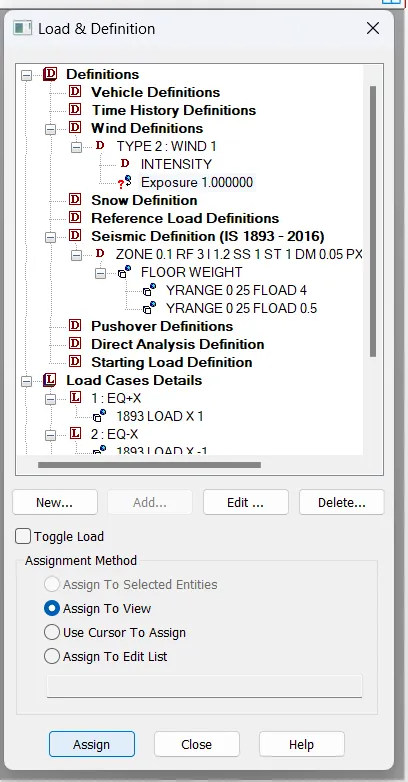
And we then assign the Exposure Factor to Nodes.
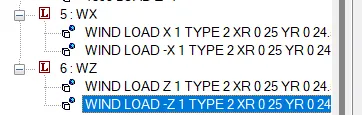
For the Wind Load,2 cases are added for 2 different directions.
Under these 2 cases,positive and negative directions wind loads are added.
We then continue by assigning the loads to structure.
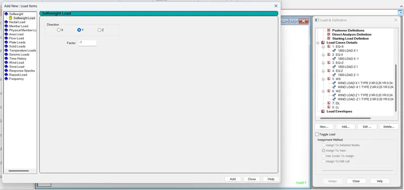
We then continue by adding the Dead Load and Live Load.
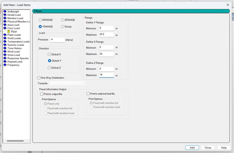
For these primary loads,we just add the Floor Weights and for the Dead Load,we even add the Self Weight factor.
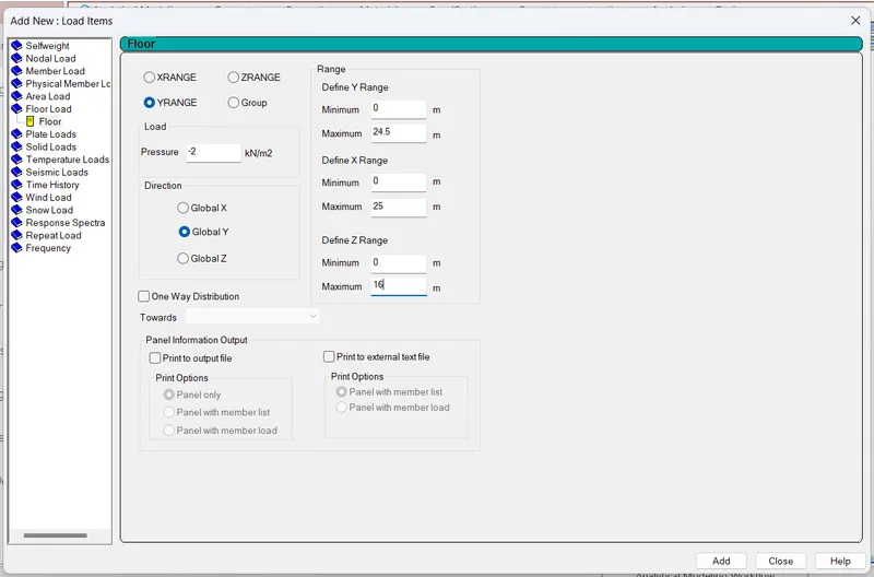
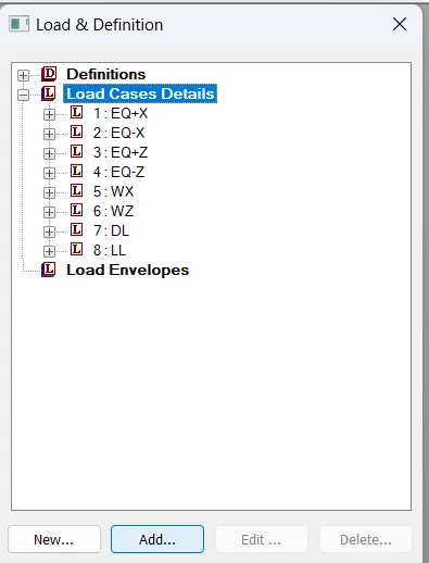
After the loads,we continue to add the Load Combinations.
To do that,we go to Loading Tab>Load & Definition>Load Cases Details>Add New:Load Cases>Auto Load Combinations.
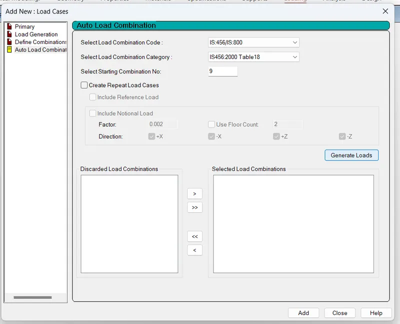
Where we use the option of Generate Loads,where the combinations are automatically gets generated.
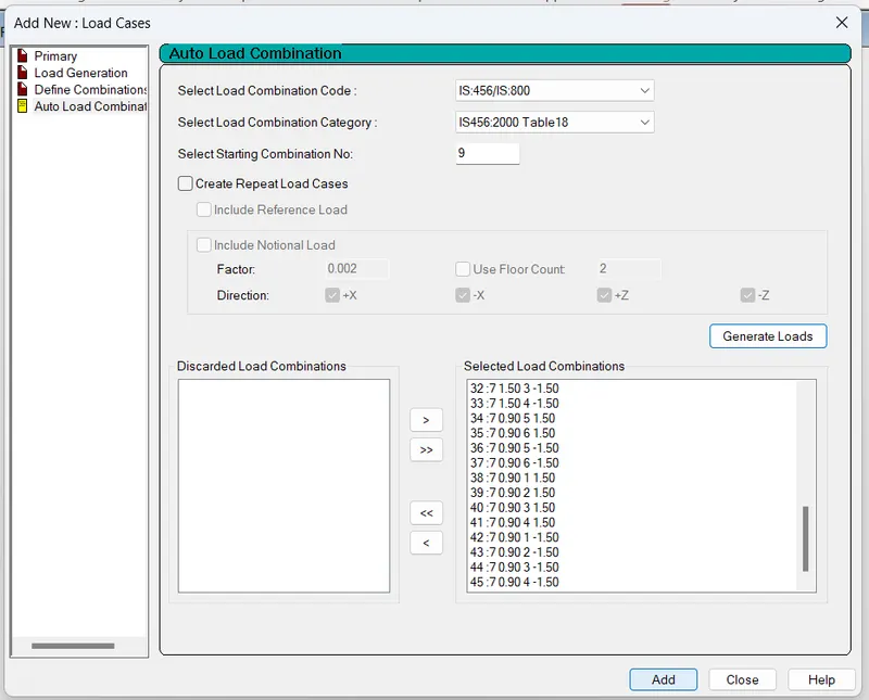
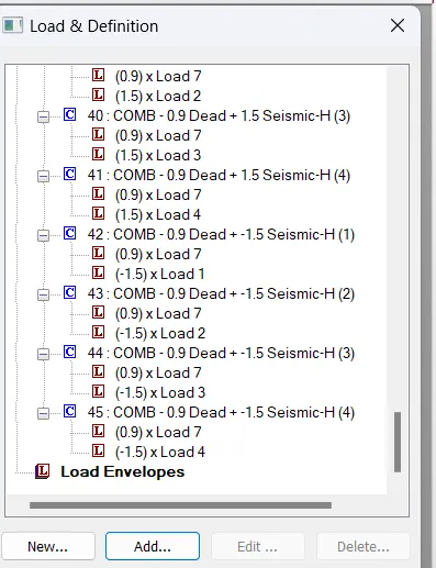
We the Add the Load Combinations.
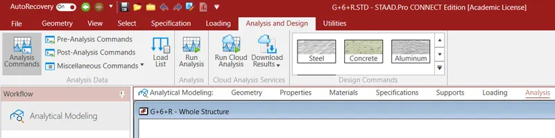
We then go to Analysis and Design Tab>Analysis Commands.
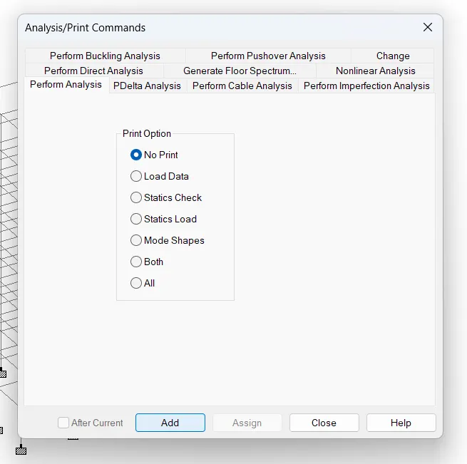
Where we then add the required analysis commands for the analysis.
We the run the analysis for the model using the option of Run Analysis.
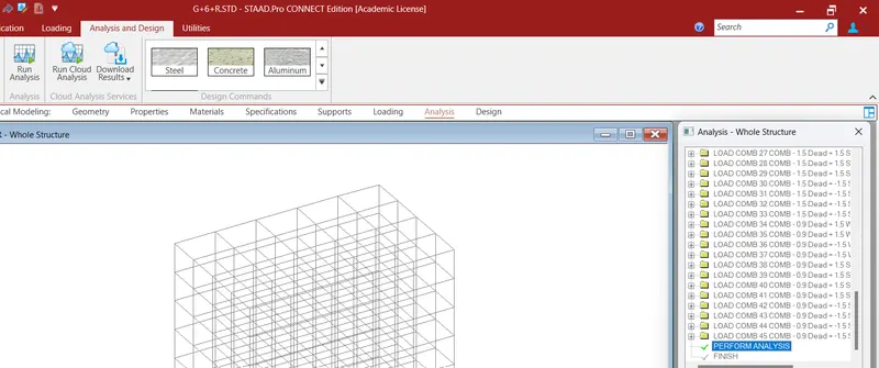
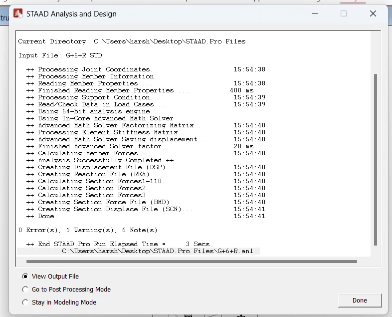
Where in the result tab after running the analysis,using the option of View Output File,we can save the file as DBR.
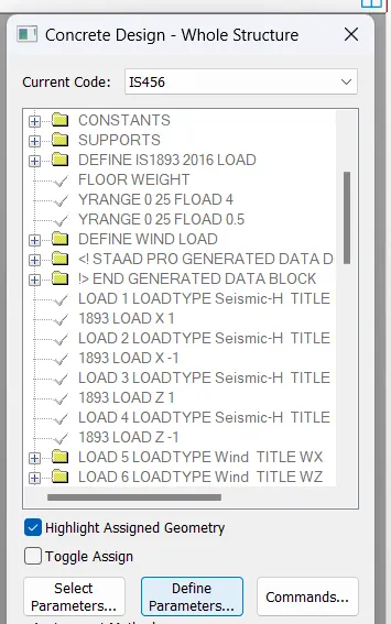
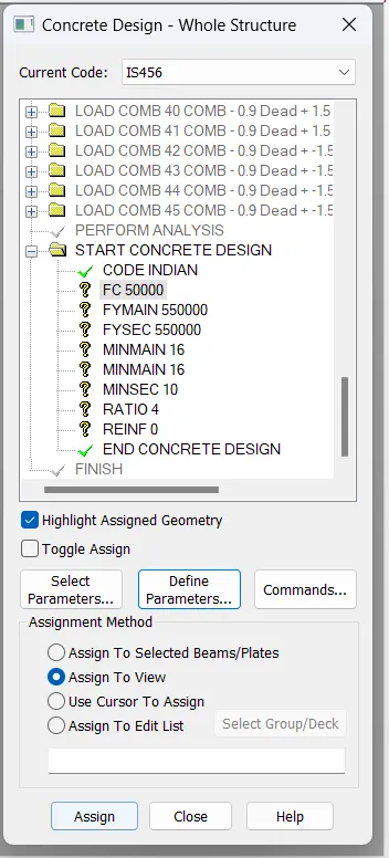
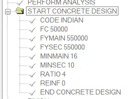
We the define the required paramaters.
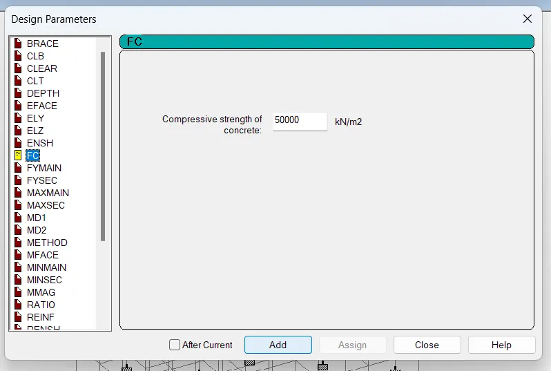
After the definition of the required parameters,we assign them to the required sections.
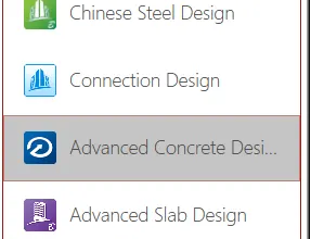
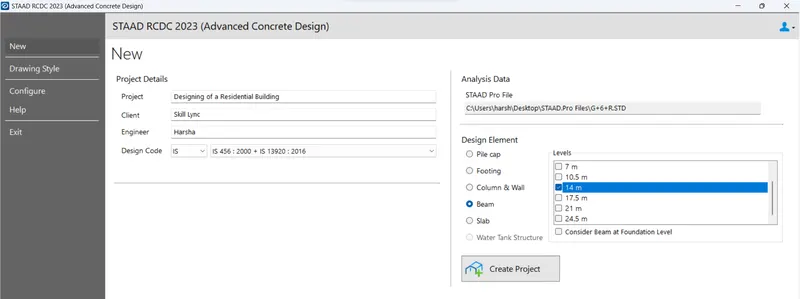
We then go Advanced Concrete Designer.
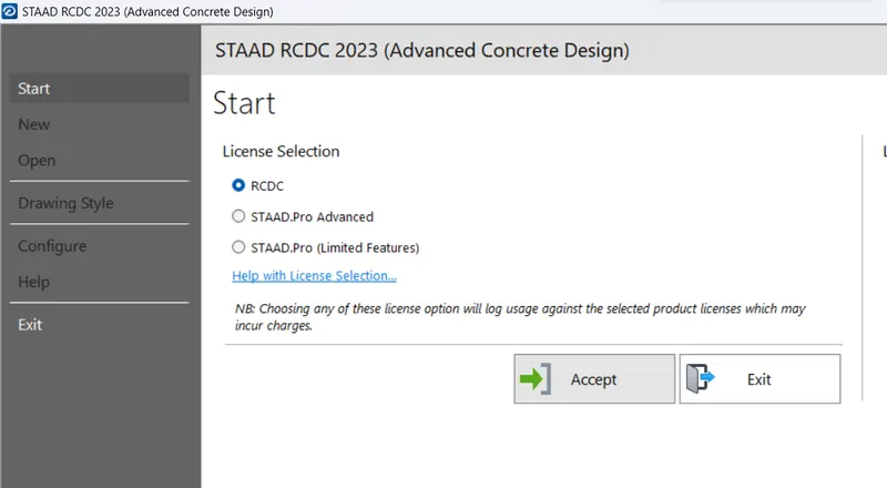
Where initially,we design a beam.
 +
+
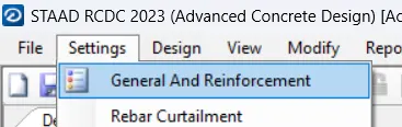
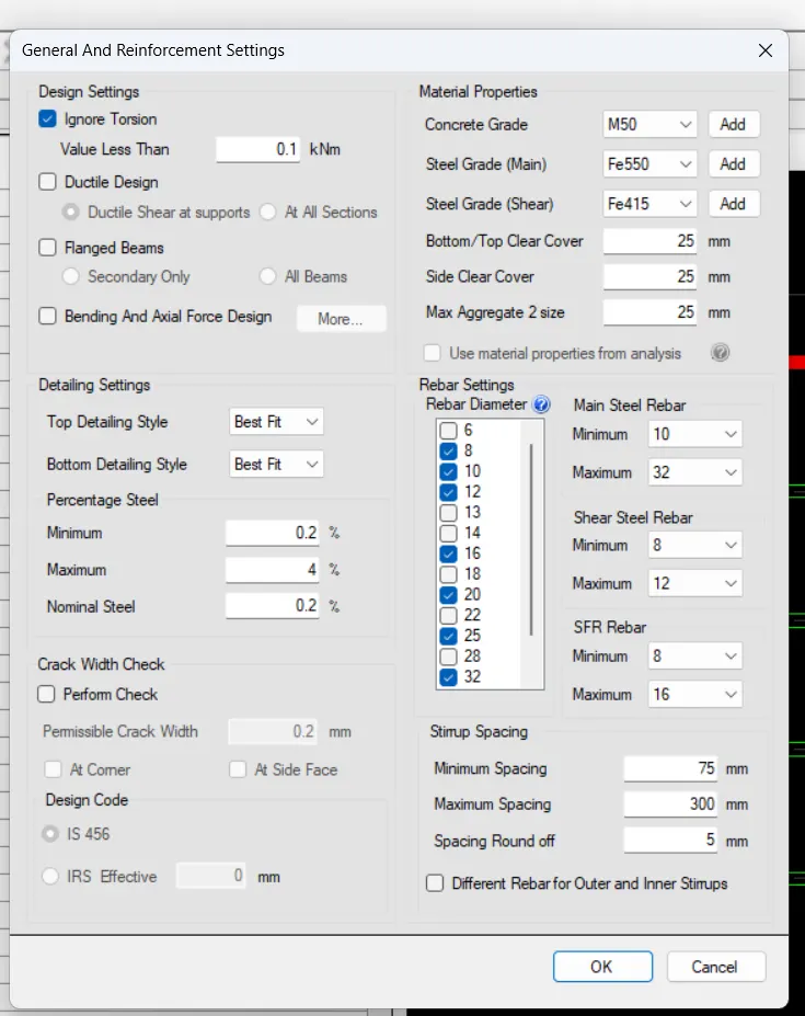
We then go to Settings>General And Reinforcement,and give the required details.
We then design the members.
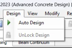
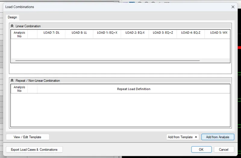
Where we give the required loads to be considered while designing.
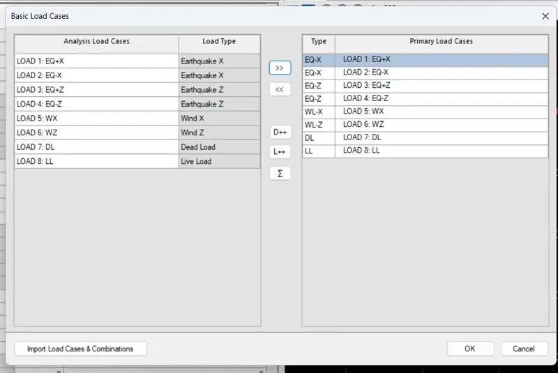
And we even add the load combinations.
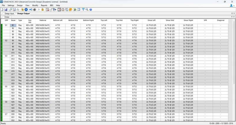
Where we can find the design summary.
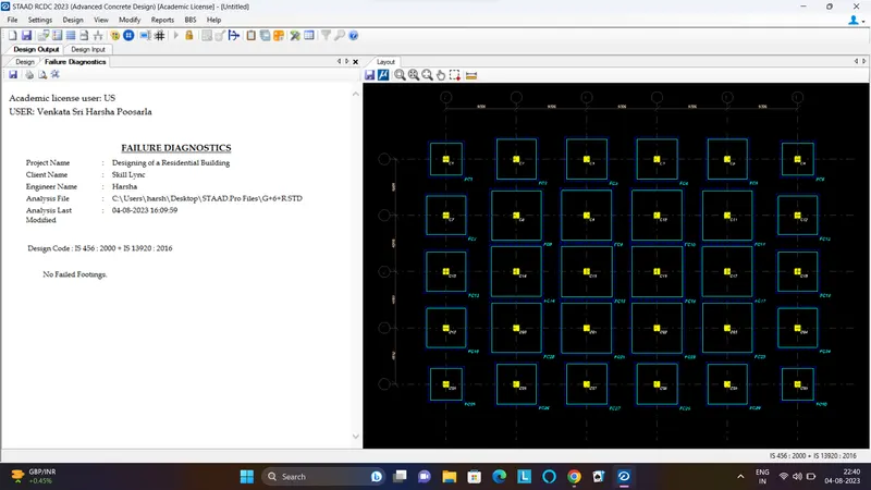
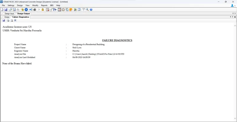
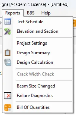
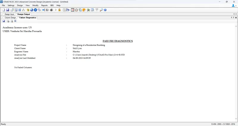
We can find the other such as Failure Diagnostics,Design Calculations,Design Summary,etc.
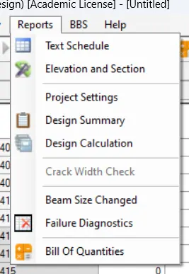
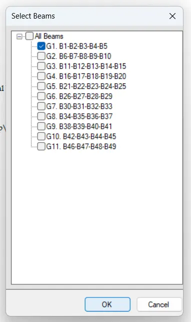
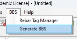
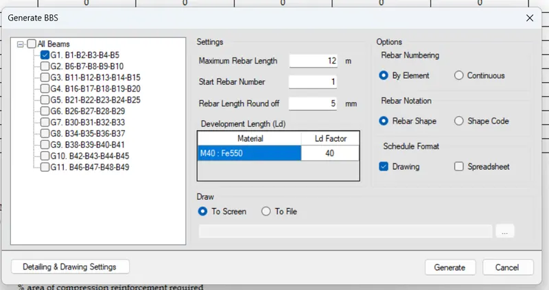
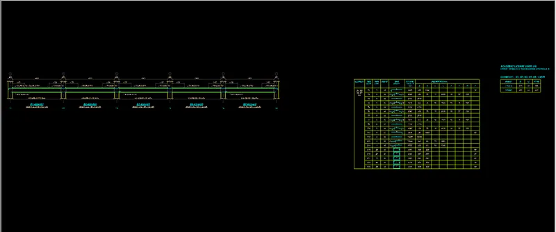
We can even generate the BBS.
In the similar manner,we go with the Columns too.
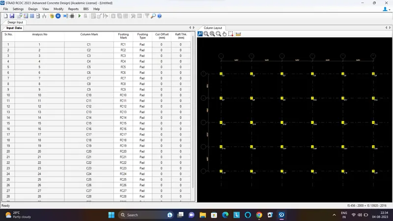
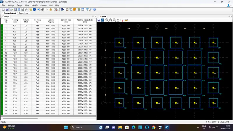
We even go with the Footings.