A Project on Wiring Harness Routing of V16 Engine
Project - Wiring Harness Routing of V16 Engine
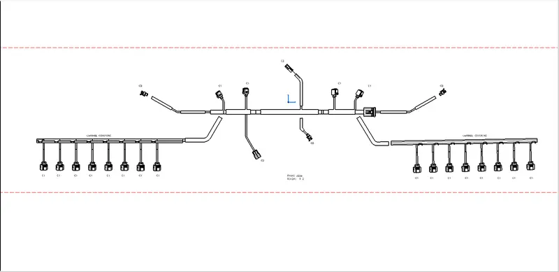
Objective: Route the Wiring harness on a V16 Engine and Prepare a flattened view drawing in CATIA V5. Application of all Packaging rules, Industry best practices studied in this course shall be demonstrated in design. Apply Protection coverings as required.
The Concept Routing of the Wiring Harness of the Engine is done as follows:
- Start by Creating a new product and name it 'Assy_Engine_Harness_context'.
- 'Assy_Engine_Harness_context' will contain the Assembly of the Engine CAD file and the Wiring Harness Geometrical Bundle.
- Define all the Connectors that are to be used for routing, and save them in a catalog
- Similarly, also define the Clips and connectors needed for the routing.
- Import all the Files into the Geometrical Bundle.
- Place all the connectors and clamps in suitable places, using desired manipulation methods.
- After all the connectors and clamps are placed define the product file as an Electrical geometrical bundle in the Wiring harness assembly workbench.
- Start routing the wire bundle as desired.
- After the routing is completed check for the bundle continuity.
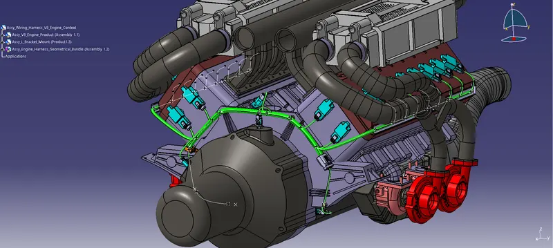
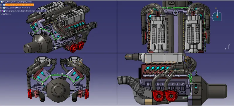
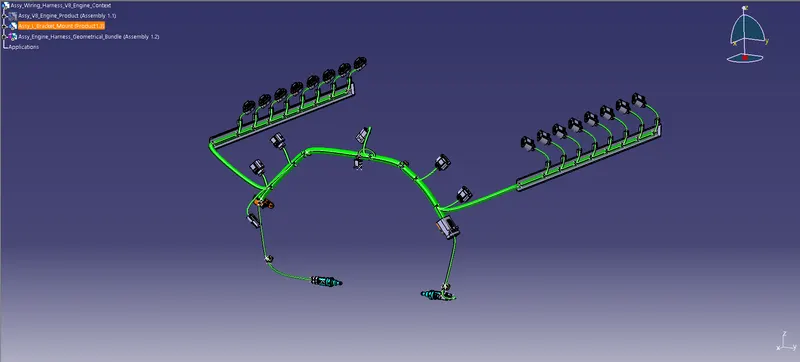
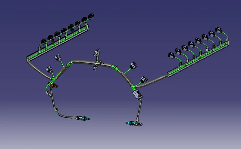
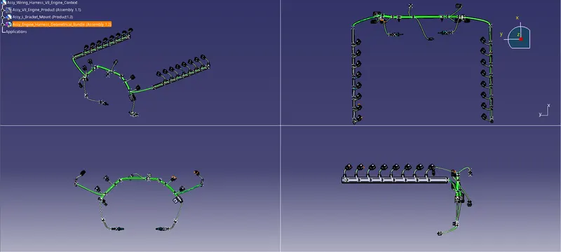
Rules and Industry Best Practices Applied to Complete the Wiring Harness Routing:
- Mounting equipment such as clips and clamps should be provided wherever necessary.
- Provide required clearance to the harness from the High temp. components.
- Provide additional slack wherever needed according to the surrounding and harness bending requirement.
- It should be made sure that there is no case of fouling i.e. the route is not passing through the component while designing the wiring harness in CAD software, additional clips/clamps may be used to avoid fouling.
- Protection should be provided as needed according to the surrounding temperature.
- The wiring harness should be easy to assemble and easy to access.
- Avoid routing over bolts, bolted joints, or screwed joints to avoid harness puncture.
- Avoid harness routing near sharp edges or else provide protection over the harness.
- The minimum distance between Clip to the branch point should be at least 25 mm.
- The minimum distance between two branch points should be at least 50mm
- Avoid direct support for harnesses on fuel lines routed in the engine.
- Avoid too many sheet metal brackets on the engine. Try to use available threaded bosses on the engine or demand for it.
- Use plastic guiding channels if needed.
- The branch Length should be greater than 50mm.
- Use of protective coverings such as corrugated tubes should be used wherever it is required.
Connectors & Supports Used for the routing
The given Engine has the following Electrical devices:
- 16 fuel injector sensors - (Connector Used - 4 Pole X 16)
- 4 cam-shaft sensors - (Connector Used - 4 Pole X 4)
- 2 Coolant & Oil temp. sensor - (Connector Used - 2 Pole X 3)
- 2 Timing sensors - (Connector Used - 3 Pole X 2)
- 1 Interconnector - (Connector Used - 12 Pole X 1)
Mounting Equipment/Supports Used:
- Fir-Tree Cable Clip
- P- Clamp (Min 20mm dia)
- L-Bracket ( Sheetmetal Design)
- Guiding Channel
The bend ratio for all the bundle segments is considered to be 1.4
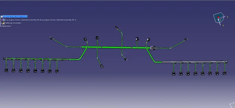
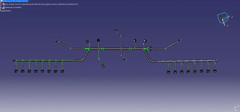
Flattening of the wiring Harness
The Flattening of the wiring harness is to be done after creating the Routing as desired in the Flattening workbench.
Input the standard settings.
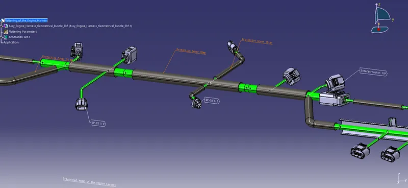
Provide the Protection coverings for the required bundles.
We can also provide the 3D annotations for the easier understanding of the Harness Bundle.