Project 1
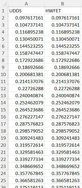
a) Creating Fuel economy numbers in Excel
Code-
%% Creating Table for Fuel Economy in Excel
if Drive_Cycle_Select == 1
load DriveCycles/UDDS;
filename ='Fuel_Eco.xlsx';
writematrix(Fuel_eco,filename,'Sheet',1,'Range','A1');
elseif Drive_Cycle_Select == 2
load DriveCycles/HWFET;
filename ='Fuel_Eco.xlsx';
writematrix(Fuel_eco,filename,'Sheet',1,'Range','B1');
end
output-
b)Time trace for Engine transmission input, Transmission output and wheel speed
For the UDDS cycle-
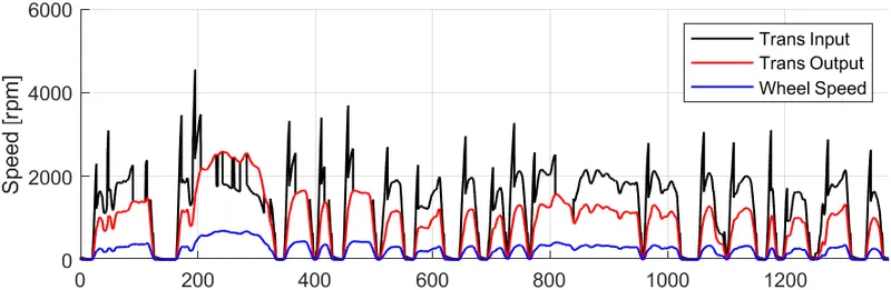
The variation in the speed depends on the UDDS cycle speed requirements. The Gear ratio causes the speed reduction It can be observed from the above plot. The Transmission output has less speed than the transmission input directly coming from the engine. This is the result of the Gearbox. After the transmission, the speed is further reduced by the final drive ratio through the differential. We get high Torque at the output because of the gear reduction.
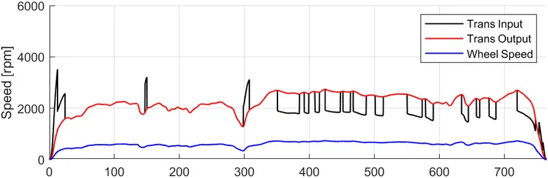
For the HWFET cycle-
c)Engine Torque-
For the UDDS cycle-
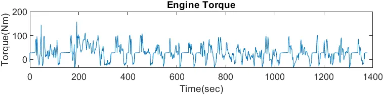
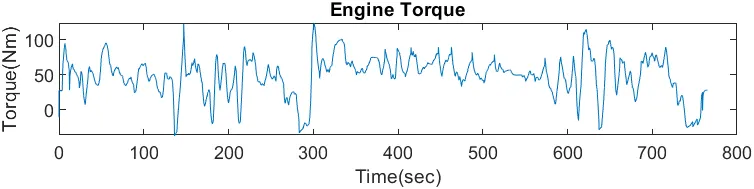
Engine torque varies according to the load of the UDDS cycle. The negative torque is the torque generated during the braking/Deceleration. It can be recovered through regenerative braking(if available). The load variation fluctuates in the UDDS cycle more compared to the HWFET cycle.
For HWFET cycle-
Engine Power-
For the UDDS cycle-
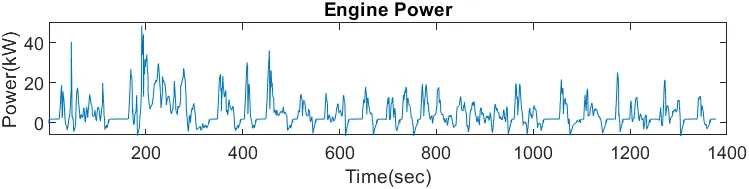
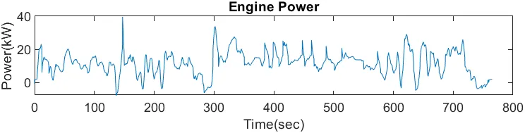
The engine power varies with respect to the load acting on the vehicle.
For HWFET cycle-
Fuel rate and Fuel consumption
For the UDDS cycle-
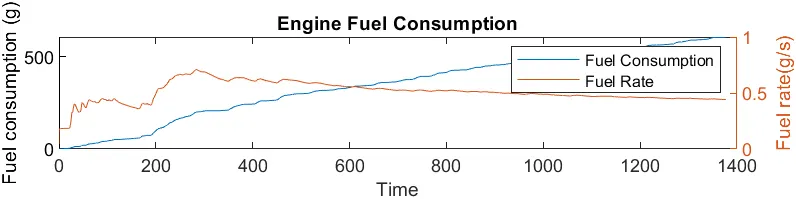
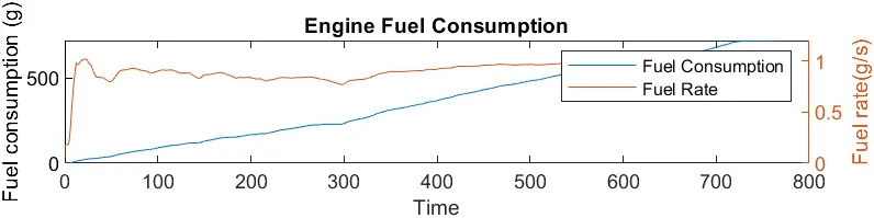
The fuel flow rate in the HWFET cycle is much higher than in the UDDS cycle. In the UDDS cycle, the accelerator pedal is not continuously pressed so the fuel consumption rate is low.
For HWFET cycle-
d) accelerator and brake pedal
For the UDDS cycle-
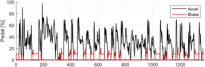
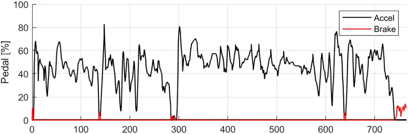
In the UDDS cycle due multiple start and stop the brake pedal is pressed frequently. In HWFET cycle the vehicle maintains constant speed so the accelerator is pressed constantly.
For HWFET cycle-
Gear command-
For the UDDS cycle-

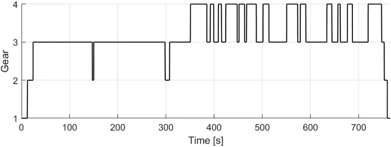
In the UDDS cycle, the driver is driving the vehicle in the first gear most of the time. The UDDS cycle has a lot of starts and stops due to this the driver drives the vehicle in the 1st gear. In the HWFET cycle, the vehicle is driven in the third gear most of the time. The HWFET cycle doesn't have a start and stops in the cycle.
For HWFET cycle-
Desired and actual speed-
For the UDDS cycle-
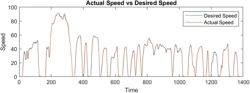
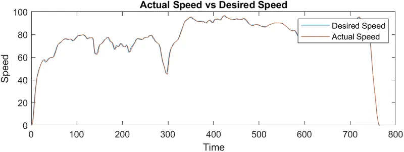
The actual speed and desired speed are nearly the same.
For HWFET cycle-
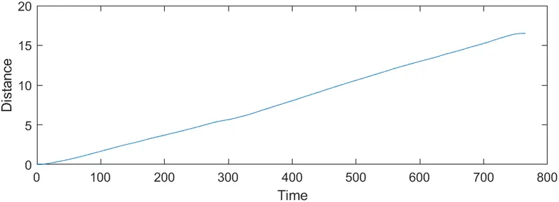
Vehicle distance
For the UDDS cycle-
For HWFET cycle-
e) Engine operating points
For the UDDS cycle-
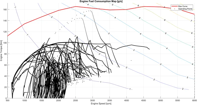
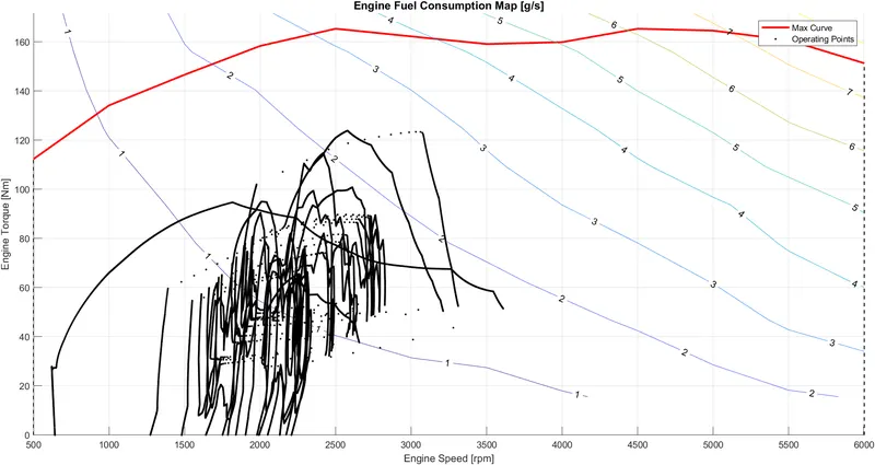
The operating points are displayed by the block dots. For the UDDS cycle, the operating points are concentrated between 1000RPM to 2200RPM. For the HWFET cycle, the operating points are concentrated between 1500RPM to 3000RPM.
For HWFET cycle-