Project 1
Title of the Project
Design of a Battery Pack for a Car.
Aim of the Project
The main Objective or Aim of the project is to,
i. Design the battery pack congifuration as per the given requirements and specification.
ii. Draw the BMS topology for this battery pack.
iii. Build 3S2P battery pack configuration with generic battery pack block using matlab and simulink.
Introduction to BMS.
A battery management system (BMS) is an electonic system that manages a rechargeable battery/cell/or battery pack by protecting the battery from operating outside its safe operating area, monotoring its state, calculating secondary data, reporting that data, controlling its environment, authenticating it and or balancing it.
Figure below shows the basic block of BMS Configuration.
BMS ia the technology dedicated to the oversight of the battery pack, Which is an assembly of battery cells, electrically organized in a ROW and Column matrix configuration as per the requiremets to enable delivey of targeted range of voltage and current for a certain duration of time for the expected load.
i.Design of battery pack.
Given Data,
Required power = 150 KW
Required Voltage = 120 Volt.
Battery capacity = 350 mAh = 3.5 Ah
Battery nominal Voltage = 3.6 Volt
We have,
No. of cells connected in series = Required voltage / Nominal cell voltage = 120/3.6 = 33.33
Note:- We always required the no of cell in Whole number so to get it we can roudoff the obtain results to its nearest Whole number i.e 33 and 34.
Rounding off the No of cell in series depends on maximum and minimum voltage requirement.
| No of cell in series |
Case-1 Roundoff to 33 |
Case-2 Roudoff to 34 |
| Nonimal Batter Voltage | 3.6 * 33 = 118.8 Volt | 3.6 * 34 = 122.4 Volt |
Since, its always better to have more voltage.
so, we have to pick case-2 which is 34 cells in series.
No. of cells connected in Parallel = Continuous current required / cell Nominal capacity
= ((150*1000)/120) / 3.5
= 1250/3.5 = 357.1428571
Rounding off the No. of cell in parallel depends on the continuous current reuirements or battery capacity.
| No. of cells in Parallel |
case-1 Round-off to 357 |
Case-2 Round-off to 358 |
| Battery capacity | 3.5 * 357 = 1249.5 Ah | 3.5 * 358 = 1253 Ah |
It is always recomended to discharege the battery current for contionous current in 1C.
since, Continous current requirement is 1250 A
so, we have to choose case-2 which is 358 cells in parallel
ii.BMS Topology
There are four types of BMS Topology
i. Centralized Topology.
ii. Master Slave Topology.
iii. Modular Topology.
iv. Distributed Topology.
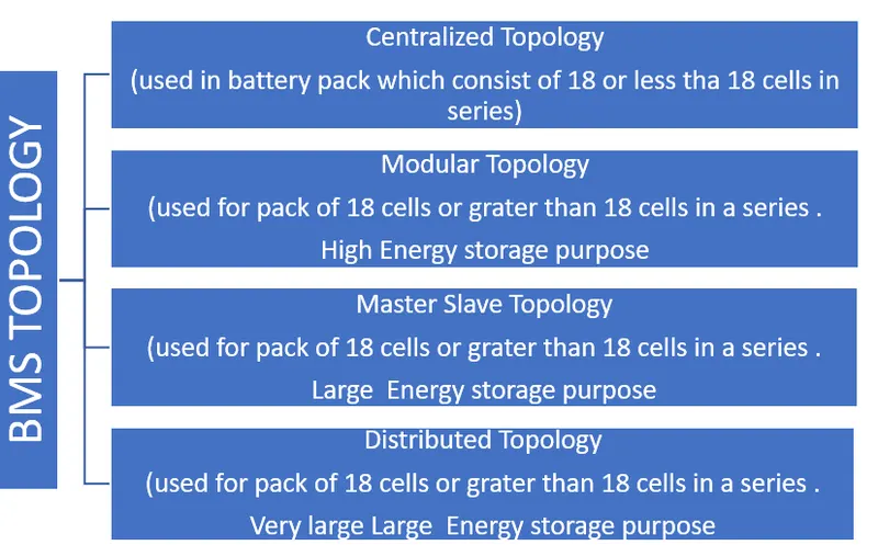
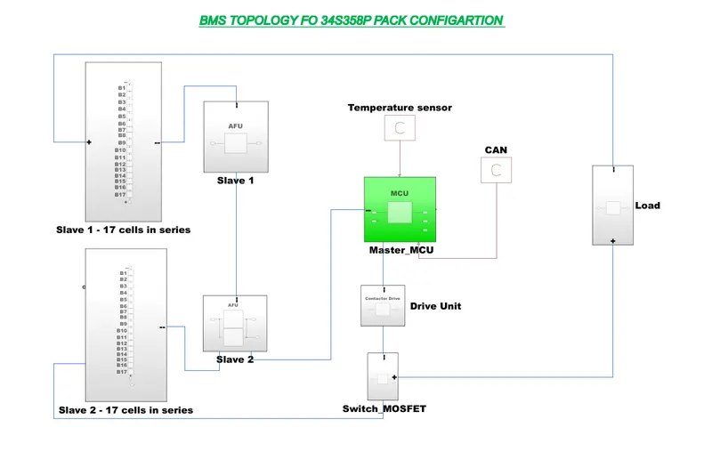
As per design the Master Slave Topology is best suitable.
To implement this we can create two battery pack model consisting 17 cells in series and 179 cells in parallel which is acting as Slave and its is combined to form a single battery Pack of 34S358P.
The Master Slave Topology for this is shown Below.
iii.3S2P Battery pack Configuration with a generic battery block using Matlab/Simulink.
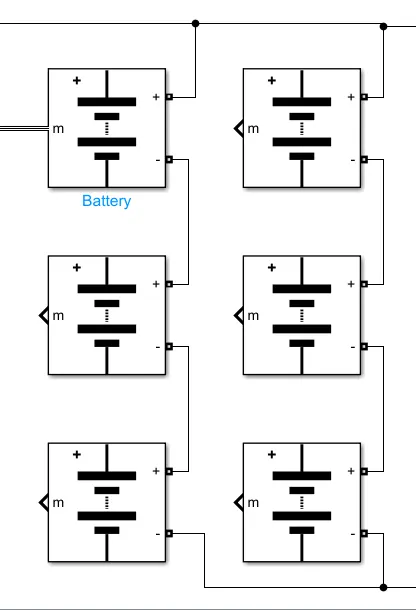
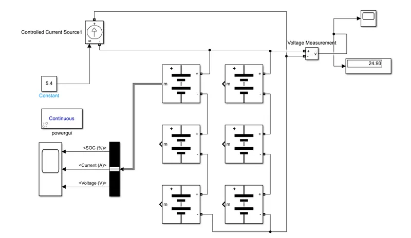
Here the total No. of cell required = 3*2 = 6 cells. From which 3 are connected in Series and 2 in parallel as shown below. The complete simulink Model is also given.
Here,
The Voltage measurement block is connected accross the battery pack (BP) to measure the BP voltage. The scope block is used to dispaly the SOC, Current and voltage. The controlled current source is used as the load to the battery pack. The constant block is connected to Cntrolled current source is the value of load i.e 5.4 Ah. its mean the load will consume or required a 5.4 A per hour.
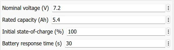
The Parameter of the battery block is set as
Therefore,
Nominal voltage of BP = No. of cells in Series * Nominal voltage of a cell
= 3 * 7.2 =21.6 volt
Rated capacity of the battery pack = No. of cell in Parallel * Rated capacity of a cell
= 2 * 5.4 = 10.8 Ah
Hence, This BP has voltage rating of 21.6 volt and Rated capacity of BP is 10.8 Ah .
Results:-
The simulation is run for 10sec. and after the 10s the SOC , voltage and current state is shown below.
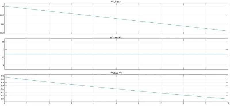
Here, the voltage result is only for 1 cells.
Note, The maximun voltage of the cell or battery is 8.3 volts
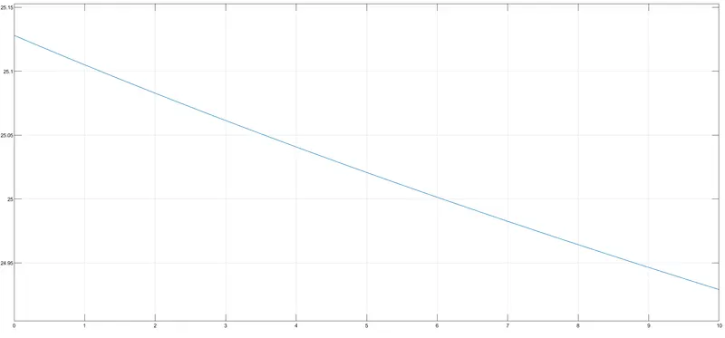
Therefore, Battery BP voltage = 8.3 * 3 = 24.9 volts
The Drop in voltage after the 10s is shown below
Conclusion
Hence the BP designed is done and from the above calculation the BP configuratuon is 34S358P. and The best suitable BMS Topology is Master and Slave.
The 3S2P BP configuration is implemented in Matlab and simulink and results is analysed.