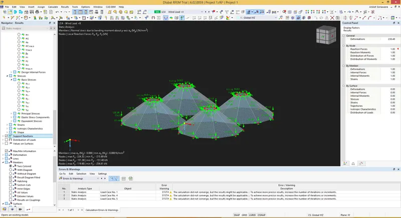
Project 1
Aim - To create a user-defined member and test the cross-section for tensile load.
Procedure -
Step 1)
i) Initially Open the RFEM software
ii) Click on New Project
iii) Enter the Project details as shown below
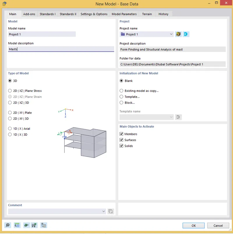
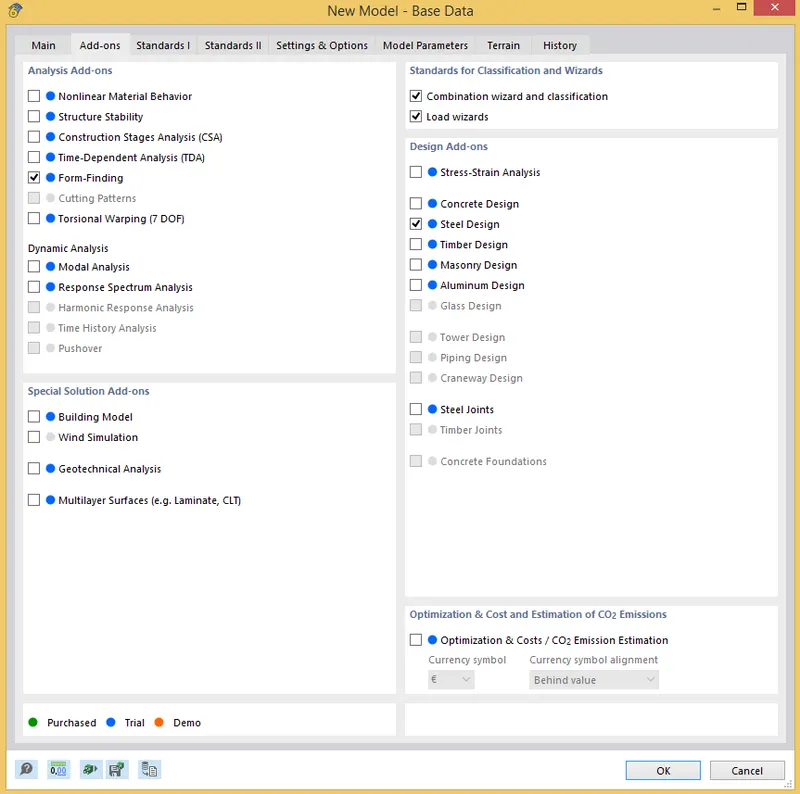
iv) Click on Add - ons
iv) Once you enter the details , Click on Okay and You will see the working space window
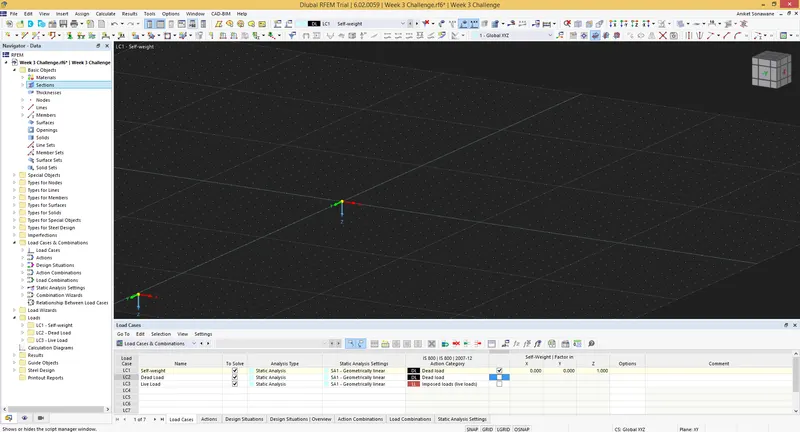
Step 2) Creating geometry
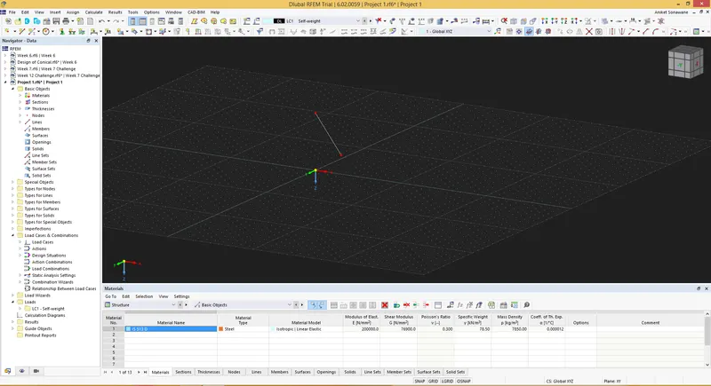
i) Click on New Node
ii) And Enter the Nodes as (0,0,5) and (2,0,4)
iii) and Draw the line
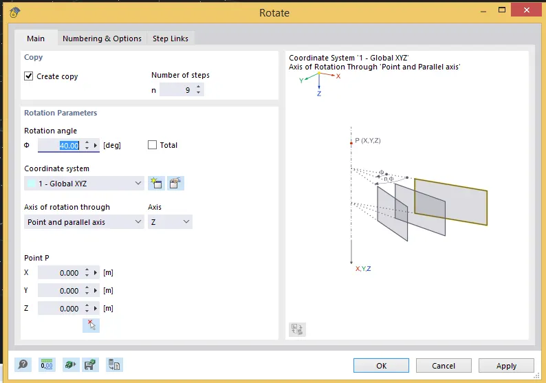
iv) Click on Rotate to create a cone shape
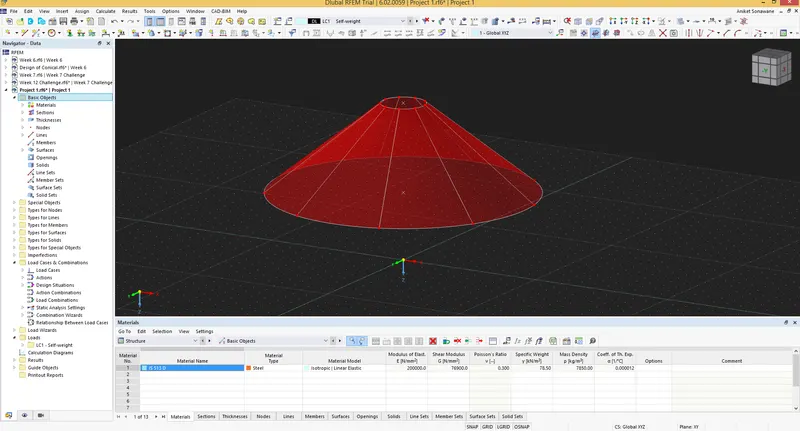
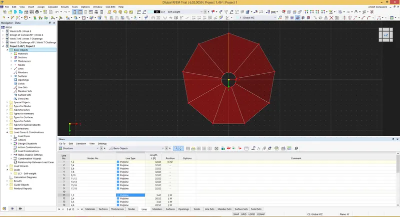
v) Convert the Arc into polyline
vi) Now we have to mirror this cone , For that Select the cone and Mirror it as shown below
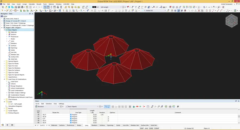
Step 2) Assign Property
i) Select the Member and Assign Cable property
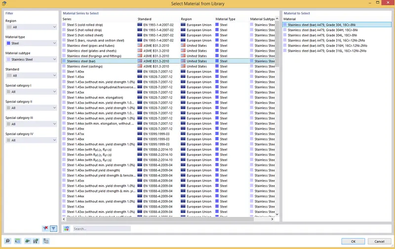
vi) Now we have to assign Support - For that Select Node 1 and Click on it and Select Hinged Support
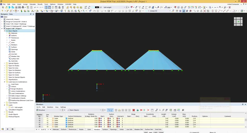
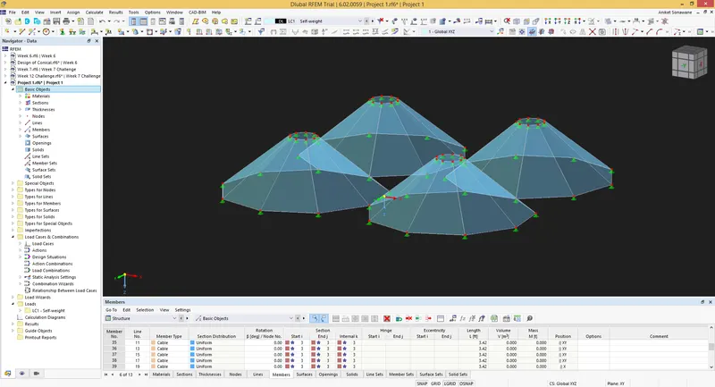
Step 3) Load cases
i) Click on New Load Cases
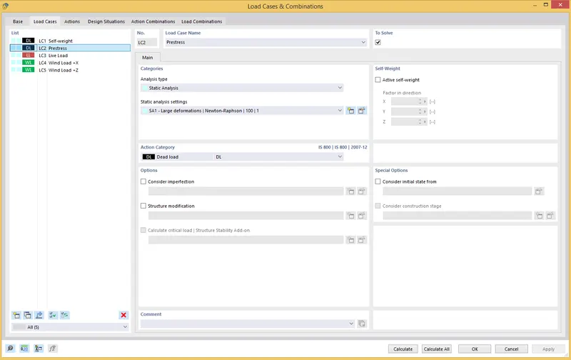
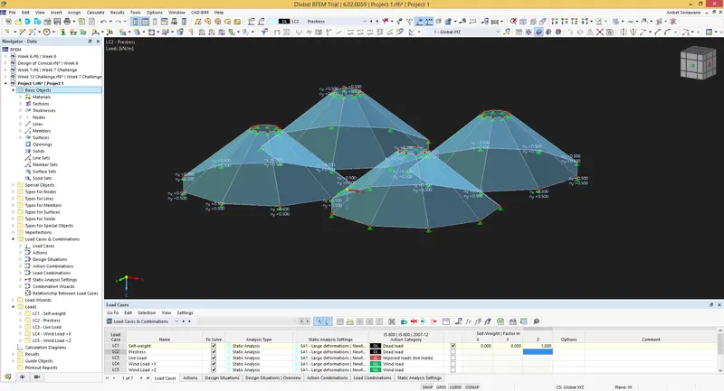
Step 4) Analysis - Form Finding
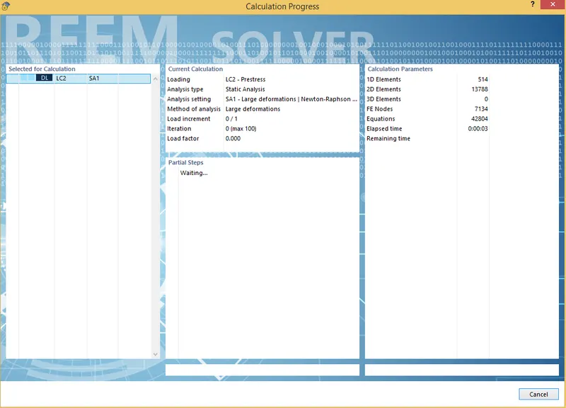
i) Click on Calculate
ii) And Run the Analysis
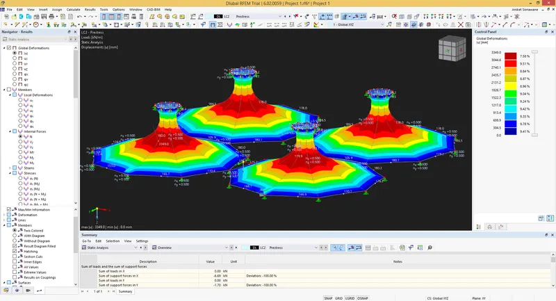
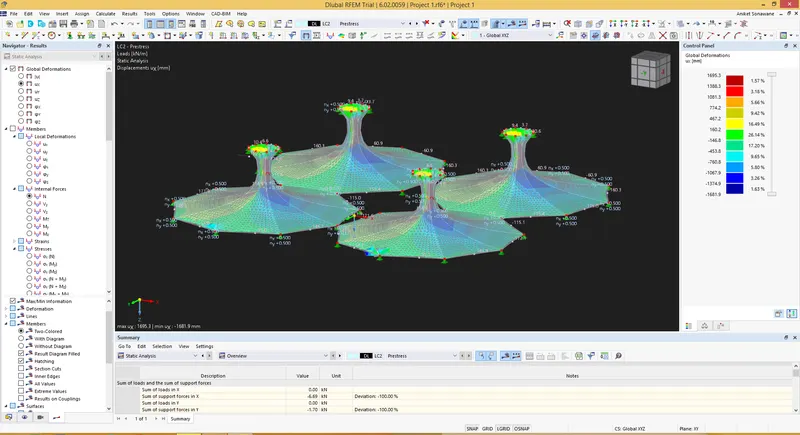
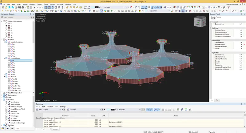
1) Axial Force
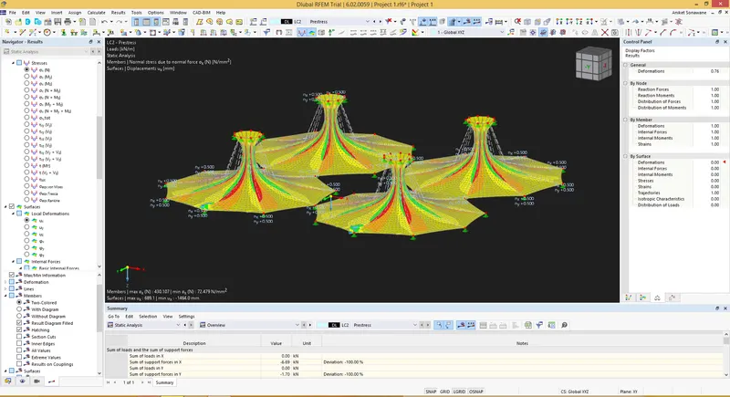
2) Surface Stresses
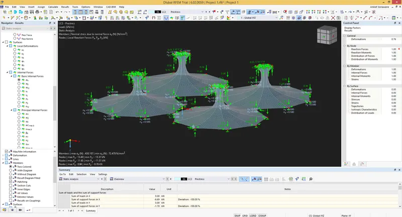
3) Support Reaction
B) Structural Analysis
i) Add the Load Cases - Live Load
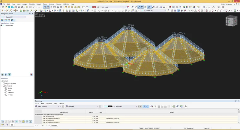
ii) Wind Load +X
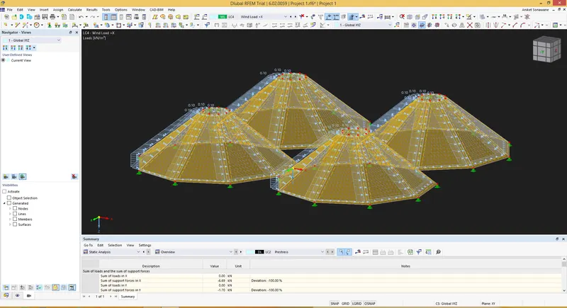
iii) Wind load +Z
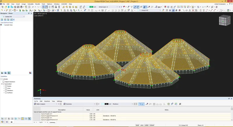
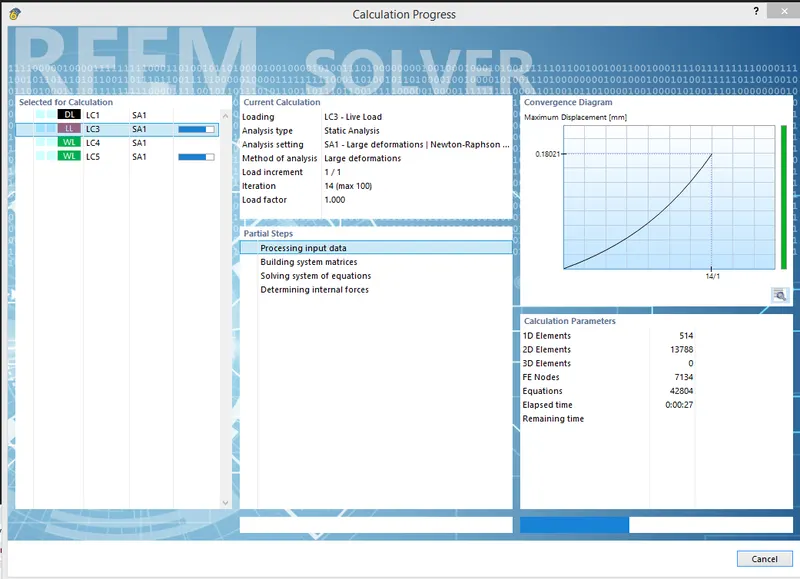
iv) Now Run the Analysis
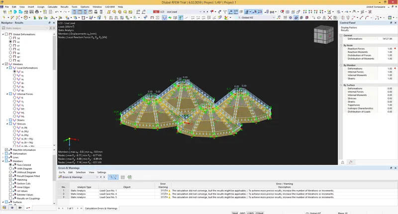
1) Axial Force

ii) Surface Stress
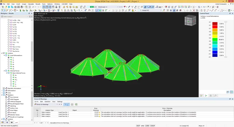
iii) Support Reactions