Project 1
Aim - To Define and Design the wiring harness routing for the given engine model and perform flattening and drafting
Methodology -
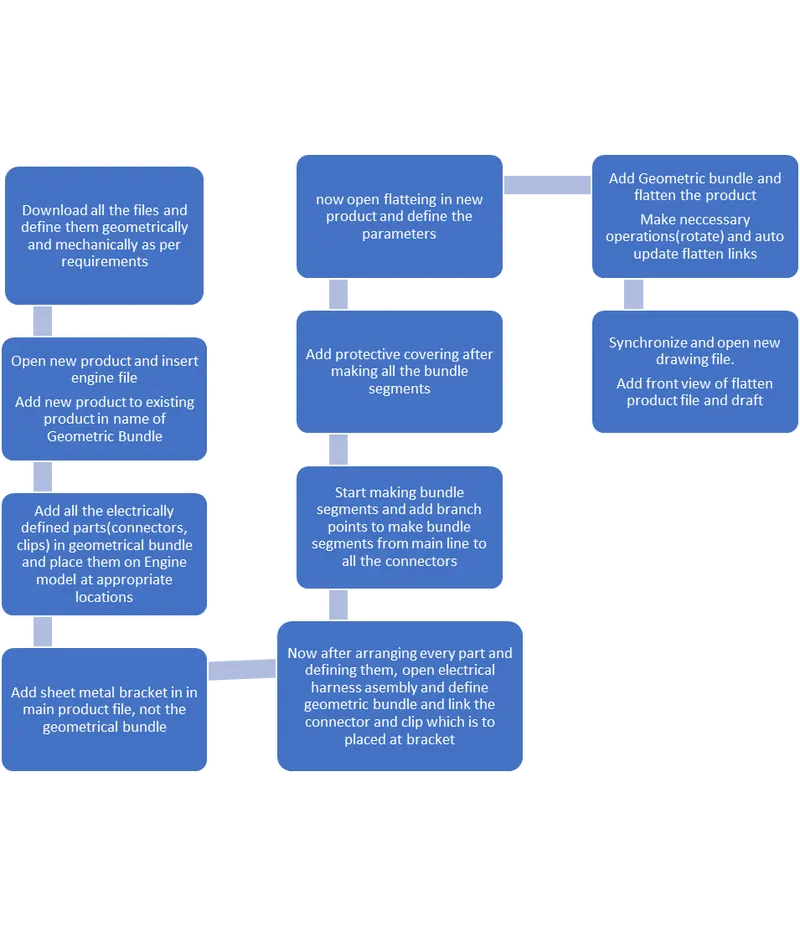
Introduction
Electric wiring harness design is a crucial aspect of developing modern engines and vehicles. It involves designing a system of wires and cables that connect various electrical components within the engine, ensuring that the system operates reliably and efficiently. The design process typically begins by identifying the electrical components that need to be connected and determining their wiring requirements, such as the type and size of wire, connector type, and routing path. This information is used to create a wiring diagram or schematic that shows the connections between the various components, including any necessary splices, fuses, or other protective devices.
Once the wiring requirements have been established, the routing of the wires and cables is designed, taking into account factors such as length, bend radius, and proximity to other components. The goal is to create a routing that provides a reliable and efficient electrical connection while also minimizing the risk of damage or interference. In many cases, computer-aided design (CAD) software such as Catia is used to create a 3D model of the engine or vehicle, including the wiring harness. This allows the designer to visualize the routing of the wires and cables in the context of the entire system, ensuring that the design is optimized for performance, reliability, and safety.
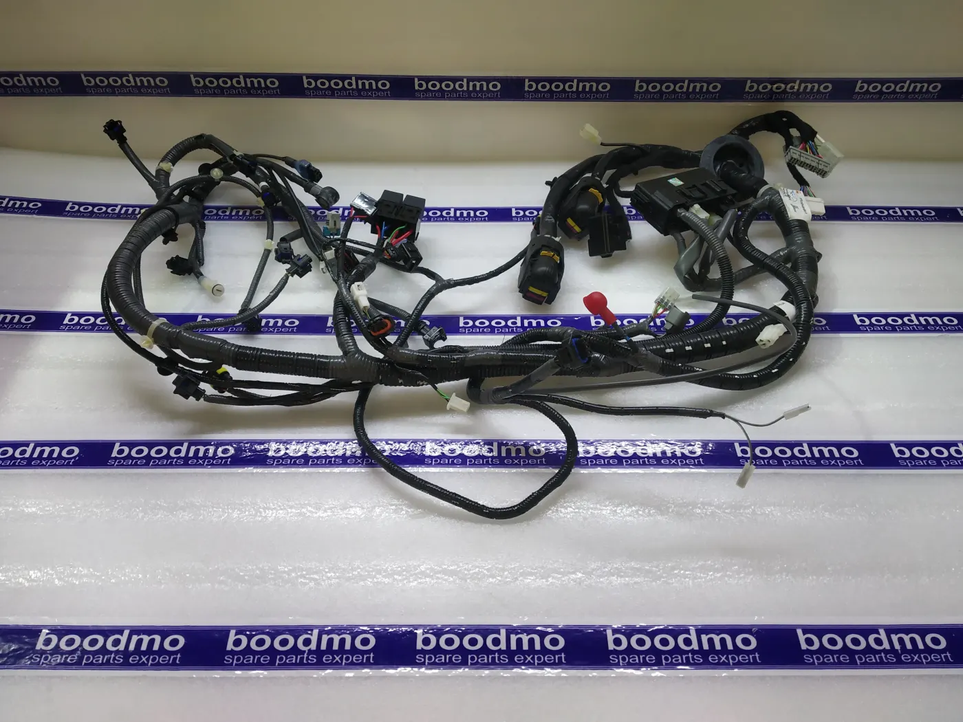
Designing an electric wiring harness can be a complex process, requiring collaboration between engineers, designers, and manufacturers. It involves not only the electrical and mechanical design of the harness itself but also considerations such as material selection, cost, and manufacturability. One key challenge in wiring harness design is ensuring that the harness is easy to install and service. This typically involves designing the harness with modular components and connectors that can be easily connected and disconnected, as well as providing clear labeling and documentation for the various components.
Procedure -
- Download the Enigne File and all the cad parts for wiring harness(connectors, clips, clamps, channels, brackets)
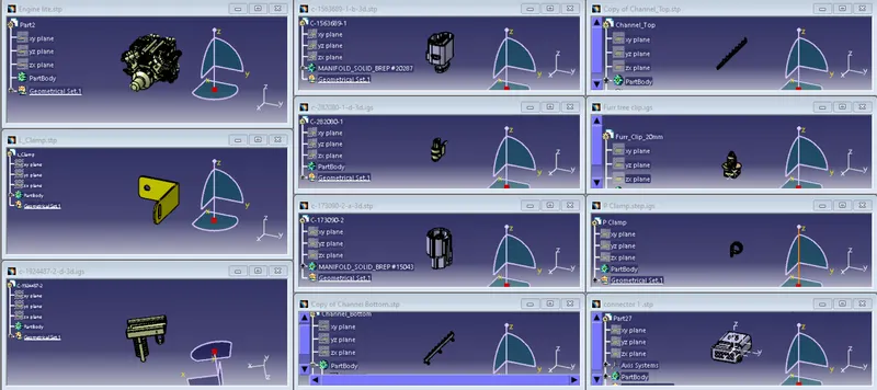
Step-1:Connectors
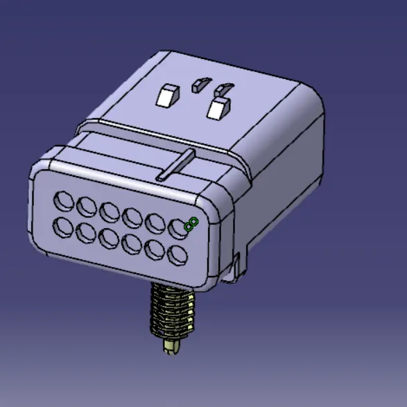
- Open the connectors Cad model in Catia part design workbench and define the model geometrically. That is to define a point and axis system at the connector connection, another point for bundle connection and add cavity connection point
- Now open the electric part design workbench and define the connector as single insert connector with required no. of terminations. Then define he above mention connections
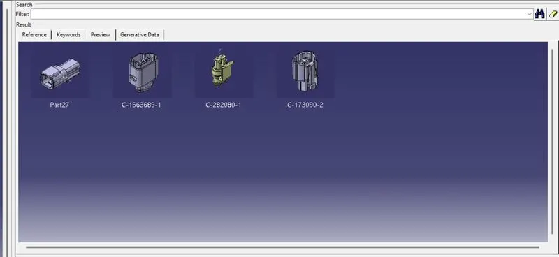
- After defining all the connectors electrically, add them in a catalogue for further use
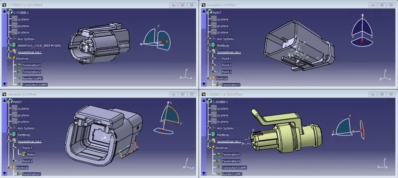
Step-2:Clip(mounting equipment) and clamps(support)
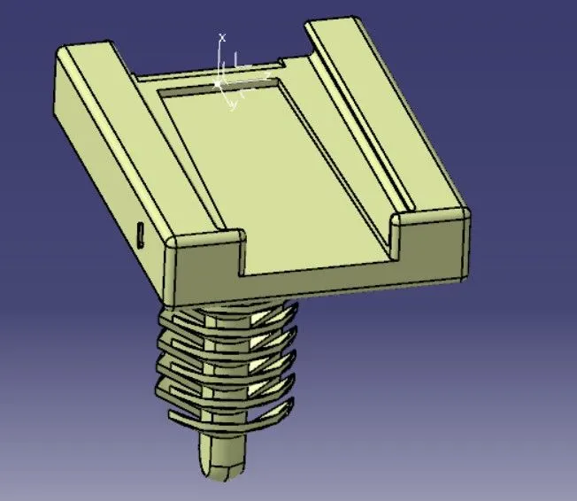
- Next is to define a clip so that connector can be mounted/linked. For that open the cad file of clip in part design and define a point and axis system at meeting side. now open the electric part design and define it as mounting equipment, then define the cavity with the point and axis system.
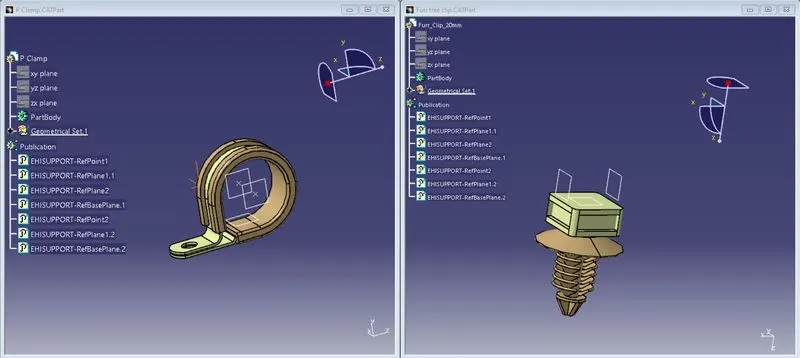
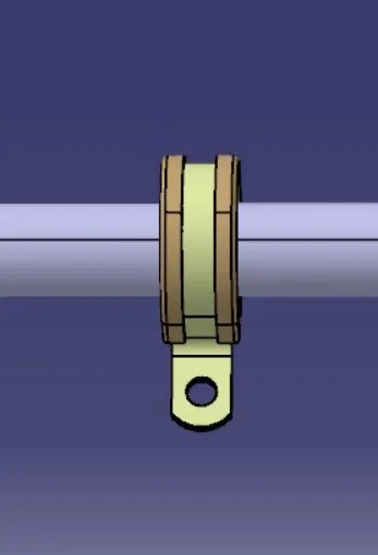
- After this we have to define the support equipment. For that open the p clamp and fir tree clip cad data in the mechanical oart design workbench and define two entry and exit planes with points and a base plane. Open electric part design and define the p clamp and firtree clip as support twice, as both sides can be entry and exit for the bundle segment
Step-3:Channel
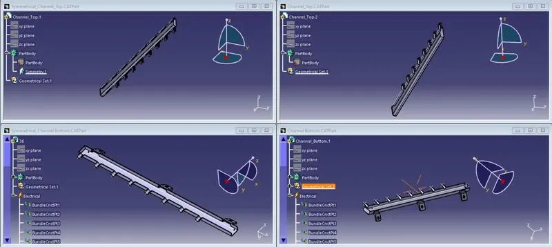
- Open the given channel bottom cad data in part design and define a point for budle segment entry and a point at 550mm near the end of channel. Now connect the points with a line
- After that add points to the channel at the bundle exits.
- pen the channel bottom in electrical bottom design and define it as electrical equipment and then define all the points as bundle connection points
- After that assemble the channel top and bottom
- Repeat the same with symmetrical channel top and bottom models.
Step-4:linking connector and clip
- Open both connector and clip in a new product file and open electrical assemby design. In that select link devices and select both connector and clip.
Step-5:Context Assembly
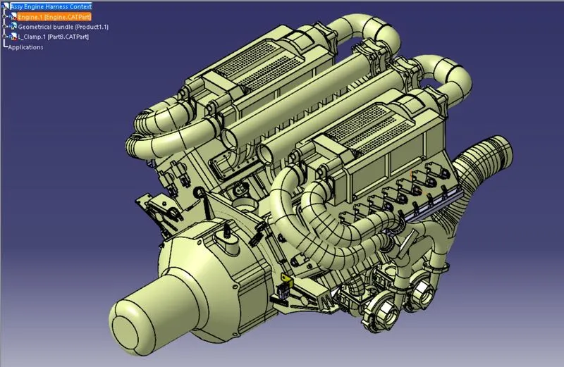
- Create a new main context assembly product file. And add Engine Cad model in th main assembly file
- Create a new product in the existing main product and name it as Geometric Bundle.Define the product as Geometric bundle in electrical workbench.
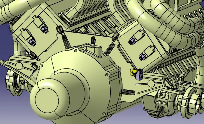
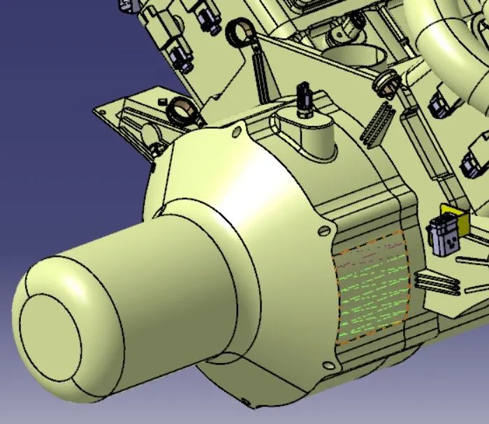
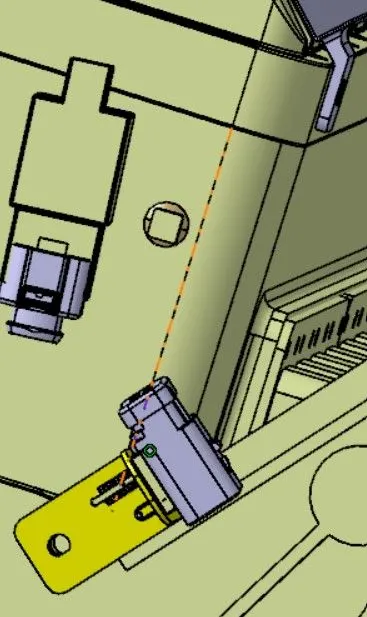
- The engine model under consideration necessitates the placement of 16 fuel injector sensor connectors, with eight required on each cylinder head. Additionally, four cam-shaft sensor connectors are required, along with one neutral position sensor connector and one speed sensor connector on the gearbox housing. The engine coolant temperature sensor is located at the center of the engine.
- Now add connector and place them at the appropriate locations by using tools like snap, smart move, manipulation and compass from assembly design workbench
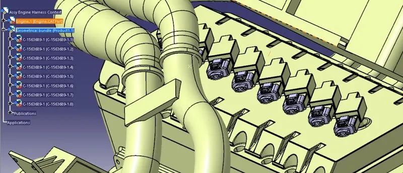
- After arranging all the connectors at correct locations, add a sheet metal bracket to the main product file, not the geometric bundle at the appropriate location by using compass, smart move and rotate. and add connector with clip to the sheet metal bracket
Step-6:Adding Guiding channels
-
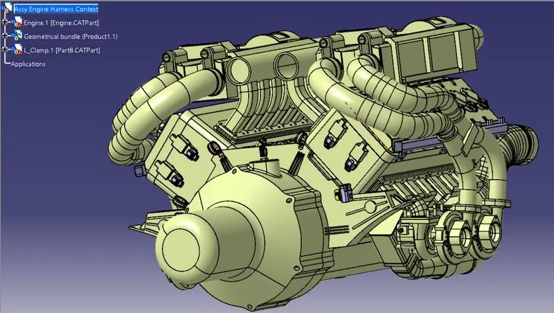
To facilitate the proper and straightforward routing of the wiring harness, we must add a plastic guiding channel to the given engine model, which has eight injectors on each side positioned very closely to each other. This guiding channel will help reduce the complexity of the wiring harness routing. We will need two distinct guiding channels, one for each side of the engine.
-
Once the guiding channel is electrically defined, we can place it at the desired location as shown in the figure above. To place the guiding channel,various commands such as manipulation, snap, smart move, compass, etc. were used.
Step-7:Mounting p-clamps and firtree clips
-
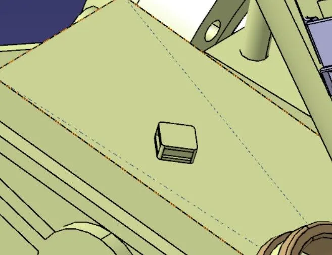
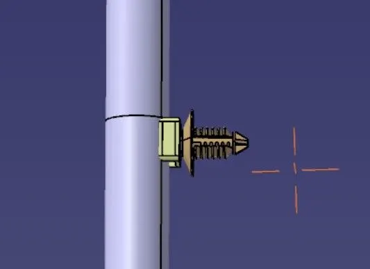
To facilitate the proper routing of the wire harness, three P-clamps were mounted on the existing bolts of the engine, as illustrated in the figure above. Additionally, to ensure a smooth path to the guiding channel on both sides of the engine, furr tree clipswere also mounted, as shown in the figure.
-
The furr tree clips, also known as fir tree clips, are widely used in automotive wiring harnesses to provide a secure and reliable attachment of wires to panels or housings. They are typically made of plastic and feature a "fir tree" shaped head that can be inserted into a mounting hole. Once inserted, the clip expands, providing a secure grip on the mounting hole and holding the wire or cable in place.
- Now all the parts required for wiring harness design have been defined and placed in context assembly at appropriate locations.After this bundle routing has to be done
Step-8:Wiring Harness Routing
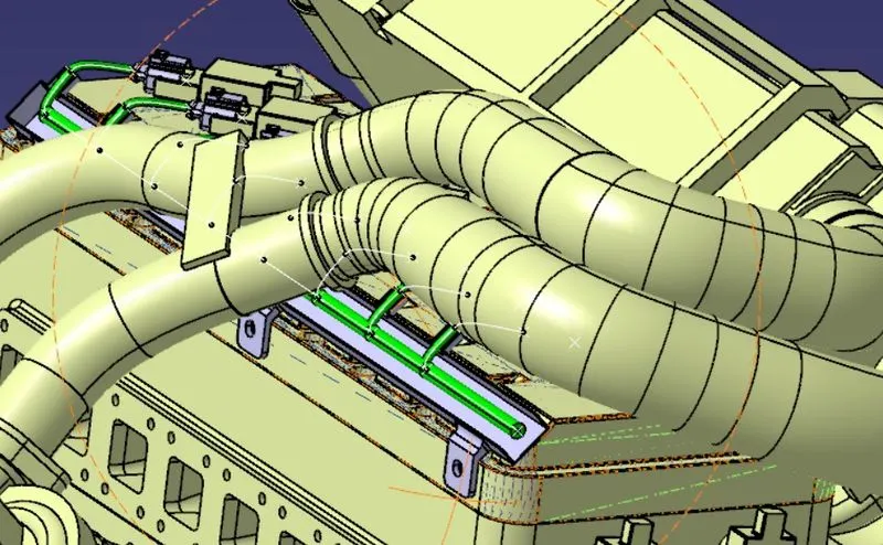
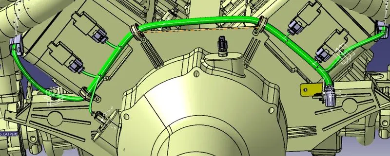
- First in the bundle segment, by selecting external curve, a bundle segment has been generated. After adding branch points, bundle segments which connect the channel bundle segment to all the connectors have been generated.
- Similarly, bundle segment has been generated at the symmentrical channel assembly too.
- To route the wire harness, we started from the interconnection connector and then directed the bundle to the P-clamps and the guiding channels. To enable routing to various connectors, branch points were added to the main branch of the harness.
- By adding branch points, we can ensure that each connector receives the required signals and power while minimizing the length of the wire segments, which reduces the overall weight and cost of the harness. Additionally, branch points allow for more flexibility in the design, as changes in the routing or components can be accommodated more easily without affecting the entire harness.
Step-9:Protective Covering
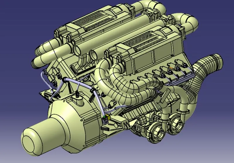
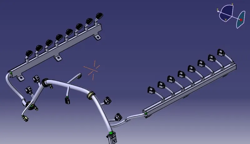
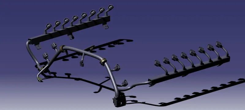
- To protect the wiring harness from high temperatures, protective coverings were added using the Define Protection Part command in the Electrical Part Design workbench.
- To use the protective covering in the harness design, we first store it as a device in the catalog by using the Store Device command and selecting the appropriate catalog file. Then, we can add the protective covering to the bundle segments by selecting the corresponding segments and choosing the appropriate covering from the catalog. By selecting the end extrinity we can give clearence.
- The protective coverings are essential to ensure the long-term reliability and safety of the wiring harness in harsh environments. They can also improve the aesthetics of the harness by concealing the wires and creating a uniform appearance. Additionally, the use of standardized protective coverings in the catalog can simplify the design process and reduce errors and variations.
Step-10:Checking Bundle Continuity
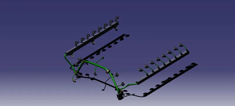
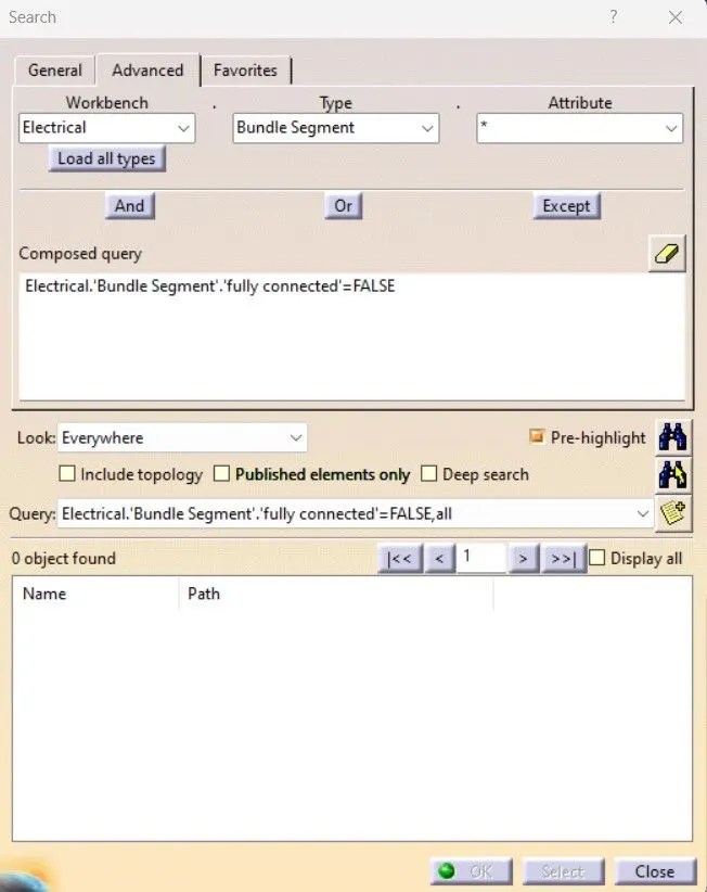
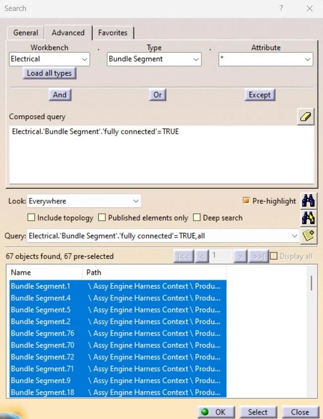
- In this particular step, we must ensure that the 'multi-branchable' option is selected, and subsequently navigate to Edit > Search > Advanced > Workbench-Electrical > Type-Bundle Segment > Attribute-Fully Connected.
- When the 'True' option is selected, all the connected bundle segments are displayed, while selecting 'False' shows all the non-connected bundle segments. In this case, we have opted for the 'True' option and searched for results. As depicted in the figure below, all the bundle segments are highlighted, indicating that they are electrically connected.
Step-11:Flattening
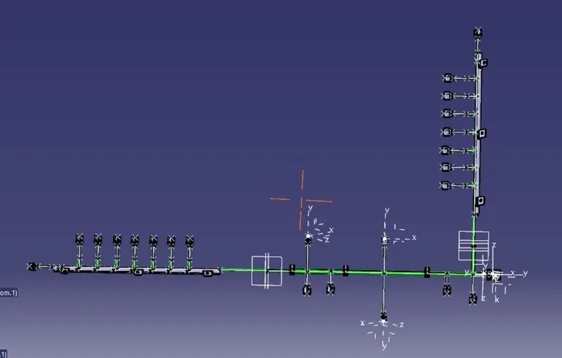
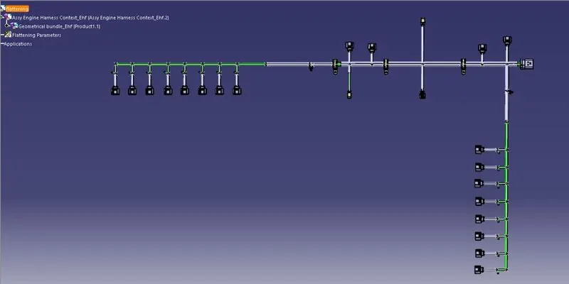
- Create a new product file for flattening and save in same folder. Open both harness flattening and main assembly parellely
- In Harness flattening Workbench, first add flattening parameters like orientations, scaling, drawing and others
- After adding them all the options for doing the operations are going to be available. Now extract the geometricle bundle in flattening workbench.
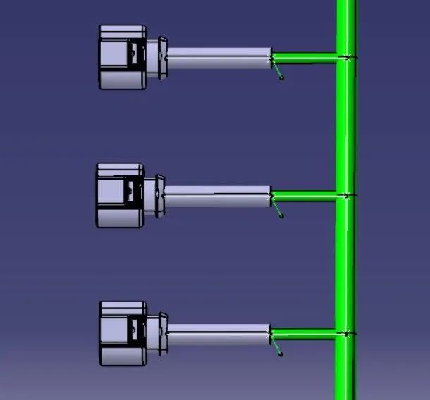
- After extract, we have to flatten it and for that we have to use flatten command, then by using rotate, bend and other features the flatten geometrical bundle is generated
- Now we have to auto update for any flatten links and synchronize.
Step-12:Drawing
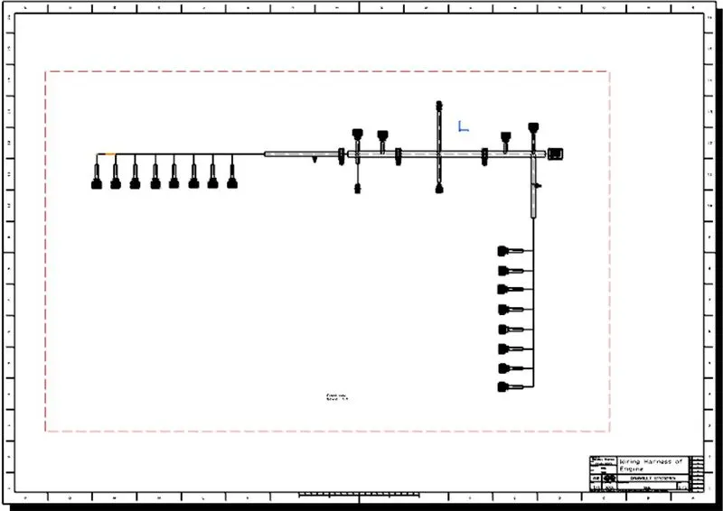
- Create new drawing file with A0 ISO sheet
- In Sheet backround add frame and title box, then in Working view add front view of flattened assembly by selecting a plane for reference
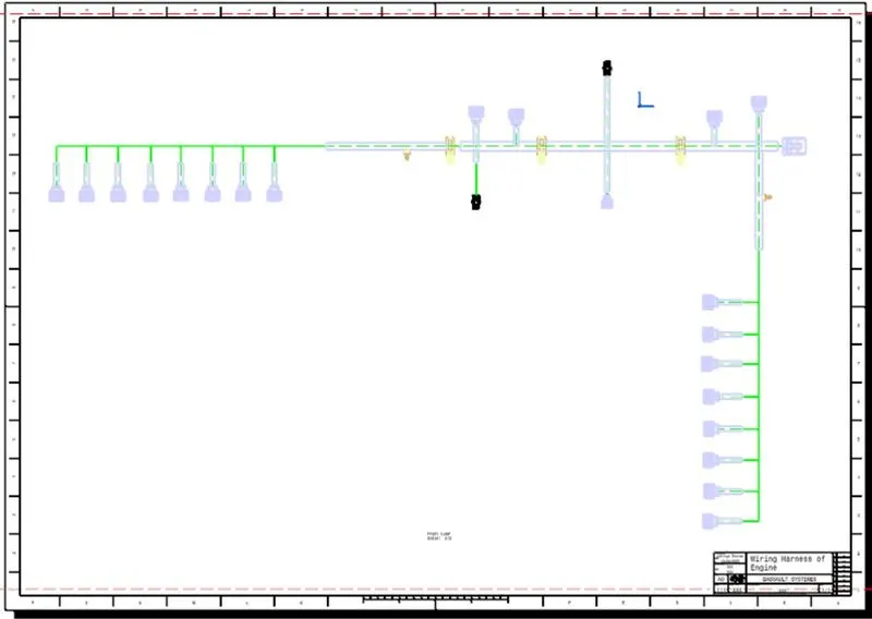
- In properties, change scale to 2:3 so that the draft fits the frame. Then in properties switch on 3D wireframe and switch on colors for differentating the components in the draft and apply them.
Conclusion:
The Defining and designing the Wiring Harness for the given Engine model has been succesfully completed by using Catia software. All the rules for packaging and routing for wiring harness have been followed while designing the routing.
Note:
For some of the corrogated tubes, i was unable to update the clearence with end extremities as software was not showing the option and I already checked with mentor and he said to proceed so please consider.
I tried uploading the zip file by using browse but i was unable to do that. So i am uploading the drive link of zip file, please use this
drive link-
https://drive.google.com/file/d/1kmwbFi580CZCj4wbhf_p8CamS71Yg2Li/view?usp=sharing