Project 1
The given engine is V16 engine and wiring harness has to be routed on this engine.
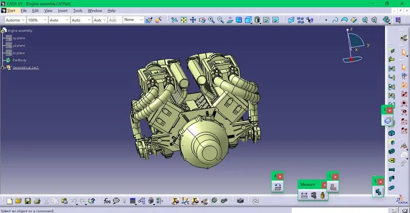
There are 16 fuel injectors with 8 on each side,2 cam shaft sensors on each engine block,1 oil level sensor ,1 sensor for measuring the engine speed and 1 sensor for finding the neutral position of transmission assembly.
The fuel injectors and cam shaft sensors require 4 pole connectors,the rest of the sensors are given 2 pole connectors.
The required connectors are downloaded ,given geometrical properties and defined as connectors.
One interconnector is also downloaded and defined .
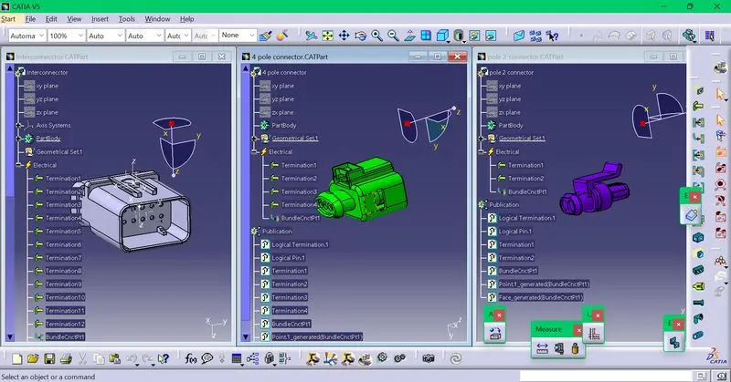
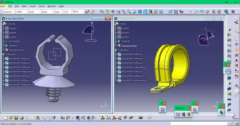
After that ,P clamp and fir tree clip are downloaded and defined as support parts for the wire routing.
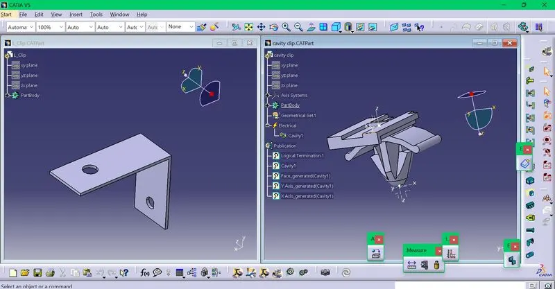
A cavity clip is downloaded and defined ,on which the interconnector will be placed.This will in turn be placed on an L clip ,which is also downloaded.
A guide channel is placed for routing the wires to the connectors on the fuel injectors.
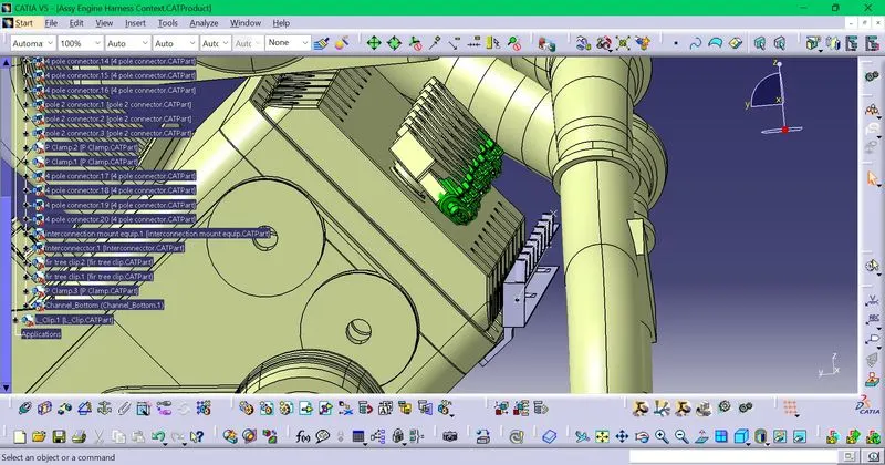
A product file is created, named assy engine harness geomterical bundle in which all the connectors are placed.The engine assembly and assy engine harness geomtrical bundle are placed in another product file named Assy engine harness context.
The connectors are placed in the appropriate positions of the engine.
4 pole connectors on the fuel injectors on each side.A guide channel is also for routing the wire to the connectors.
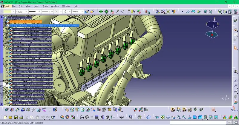
4 pole connector on each engine block.
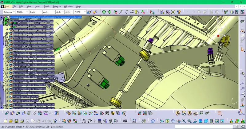
2 pole connector on the sensor position
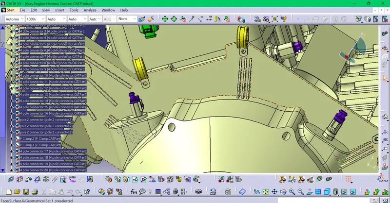
The P clamps are placed on the appropriate mounting points for routing the wire.
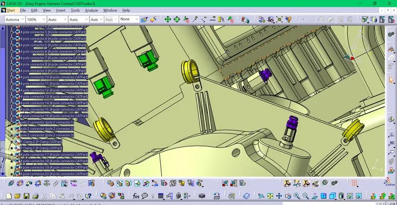
The fir tree clips are also placed at the appropriate points.
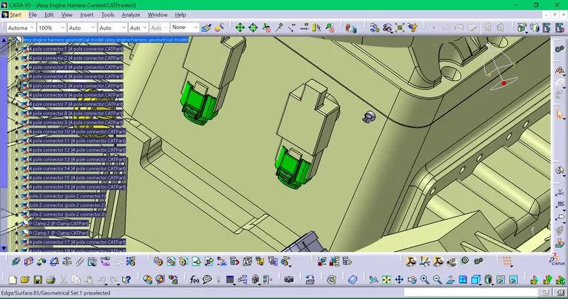
The interconnector is kept on the cavity clip which is kept on the L clip.The L clip is kept at the appropriate mounting position.
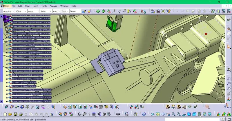
After the placements are done,we go into the electrical harness assembly.There the geometrical bundle file is selected and the bundle definition is done.
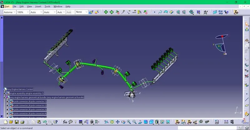
After wire routing,the bundle connectivity check is done.
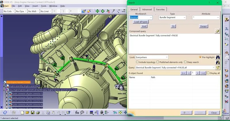
There is nothing shown as not fully connected,therefore the bundles are fully connected.
After routing the wire,the protective covering is done.
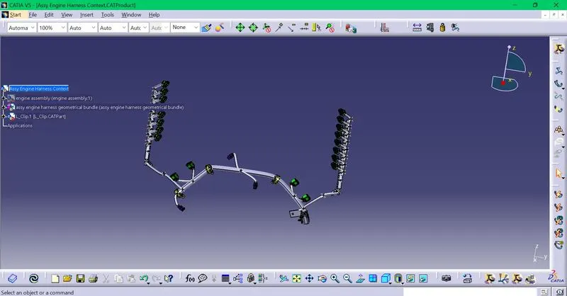
5 mm is given from the end extremity (connectors) for the protective covering.
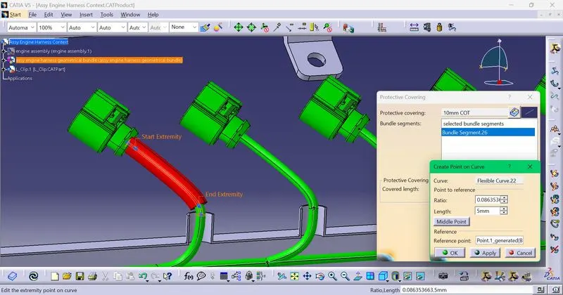
After all that,go to file,new and click product .Then select product,go to electrical harness flattening
set the flattening parameters and click extract and select the assy engine harness geometrical bundle and the wiring harness would appear in that .Rename the product file as Assy harness flattening
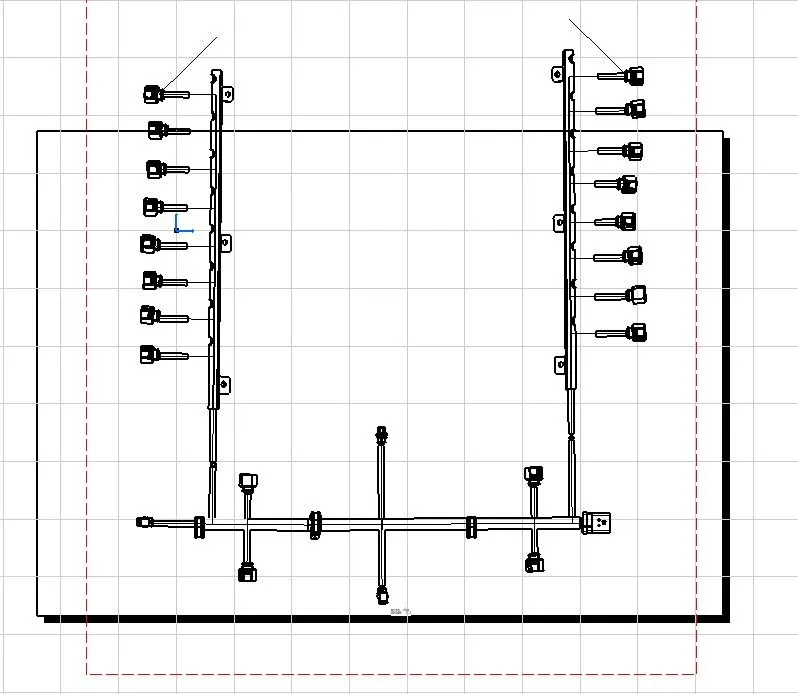
Click the flatten option and select a plane and click ok.The flattened harness assembly can be obtained.
use the rotate option and compass to align the wires and components in the appropriate manner.
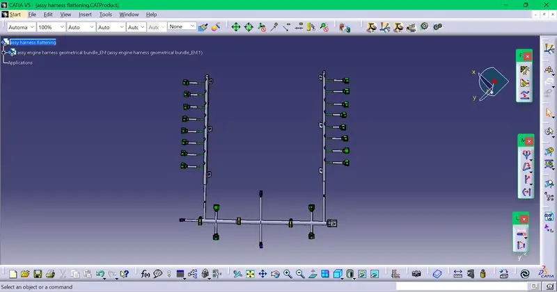
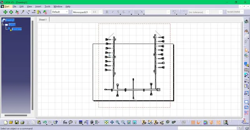
After this,click file ,new and drawing.In that ,click on the front view and go the flattened wiring harness window and click the wiring harness.
Then correctly align the drawing obtanied,also select the required options in the properties option.