Project 1
Study#1:a)
To design the battery pack configuration, we first need to calculate the number of cells required to achieve a voltage of 120V and a capacity of 150kWh.
Voltage per cell = 3.6V, Total voltage required = 120V,
Number of cells in series = Total voltage required / Voltage per cell
Number of cells in series = 120V / 3.6V
Number of cells in series = 33.33 cells = 34 cells
Capacity per cell = 3500mAh = 3.5Ah
Total capacity required = 150000/120 = 1250 Ah
Number of cells in parallel = Total capacity required / Capacity per cell
Number of cells in parallel = 1250 Ah / 3.5Ah
Number of cells in parallel = 357.14 cells = 358 cells
Therefore, the battery pack configuration will have 34 cells in series and 358 cells in parallel i.e, 34S358P battery pack configuration, resulting in a total of 12172 cells.
B:) The Master Slave BMS topology should be used for this battery pack to connect 34 cells in series
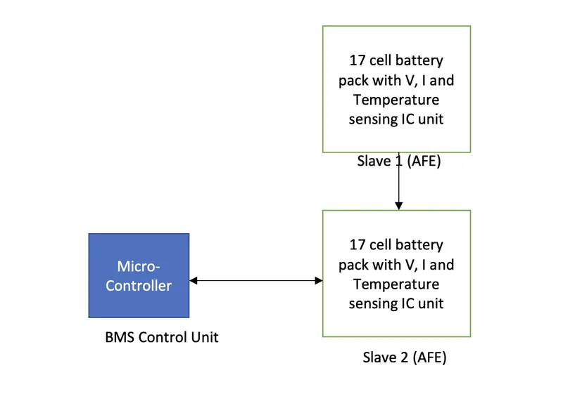
In a Battery Management System (BMS), the master-slave topology is used to monitor and control the individual cells within a battery pack. The BMS master device is responsible for monitoring the overall health and performance of the battery pack, while the slave devices monitor the voltage, temperature, and state of charge (SOC) of each individual cell.
The master device communicates with each slave device to gather real-time data on the individual cells' conditions. The slave devices continuously monitor the cells and report their status back to the master device. Based on the data received from the slave devices, the master device can take actions to balance the cells, control the charging and discharging of the battery pack, and protect the cells from overcharging or over-discharging.
The master-slave topology in BMS is critical for maintaining the overall health and safety of the battery pack. The BMS master device continuously monitors the status of the battery pack and can alert the user if any cell is not functioning correctly. Additionally, the master device can take action to protect the battery pack and prevent any hazardous situations from occurring.
Hence, the master-slave topology in a BMS allows for centralized control and monitoring of the individual cells within a battery pack, ensuring the overall health, safety, and performance of the battery system.
Study#2:
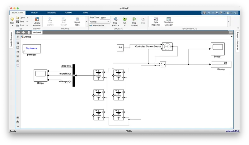
3S2P battery pack configuration with generic battery block using Matlab/Simulink:
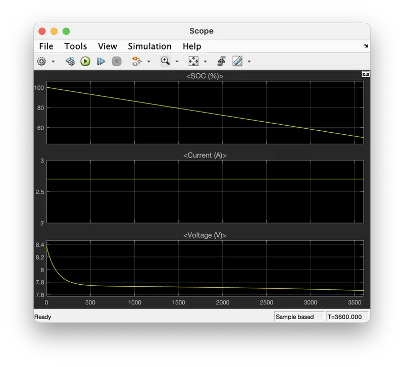
Results:
-
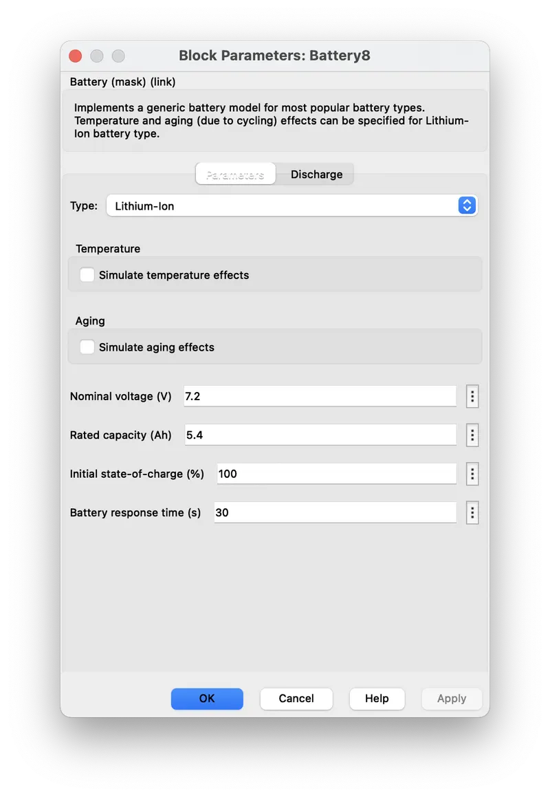
The total nominal voltage of the battery pack is 21.6V (3 x 7.2V), and the total rated capacity is 16.2Ah (2 x 5.4Ah).
-
The 3S2P configuration means that three battery cells are connected in series, and two sets of three cells are connected in parallel. This configuration allows for a higher capacity and longer runtime compared to a single cell.
-
The model built using Matlab/Simulink represents the battery pack configuration with voltage sources representing each cell, connected in series and parallel, and a load block to represent the device being powered by the battery pack.
-
The model can be simulated to test the behavior of the battery pack under different load conditions and to optimize the battery management system.
In conclusion, the 3S2P battery pack configuration built using Matlab/Simulink with nominal cell voltage of 7.2V and rated capacity of 5.4Ah is an efficient way to increase the total capacity and runtime of a battery system while maintaining a reasonable voltage level. The model allows for simulation and testing of the battery pack under different load conditions and can be used to optimize the battery management system for maximum efficiency and performance.