Project 1
WIRING HARNESS:
A wire harness is an exterior sheath that is used to protect certain types of electronic wires. Wiring harnesses are typically made of thermoplastic or thermoset materials, which help protect the cables from the environment. An engine wiring harness is a bundle of wires, cables, terminals, and connectors that control the electrical system of a vehicle. Each component of your vehicle receives power from an engine wiring harness. It is critical to the vehicle's operation and is typically made of heat-resistant rubber to withstand the high and low temperatures that vehicles frequently encounter. The engine wiring harness contains numerous cables that connect electricity to your vehicle's parts and sensors, ensuring that everything in your vehicle is in working order.
PROCEDURE:
DOWNLOAD & DEFINE:
Download the given engine CAD, connectors, mounting parts, and plastic channel, and define the electrical properties for each connector and mechanical part as shown below
- CREATE OF THE CONNECTION MIDPOINT & AXIS SYSTEM
- DEFINE THE PART AS ELECTRICAL EQUIPMENT
- DEFINE CONNECTOR CONNECTION POINT
- DEFINE BUNDLE CONNECTION POINT
- DEFINE ELECTRICAL CONNECTION
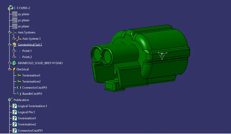
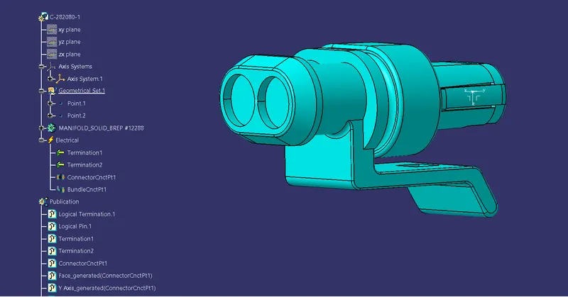
2-POLE CONNECTORS
C-73090
C-282080
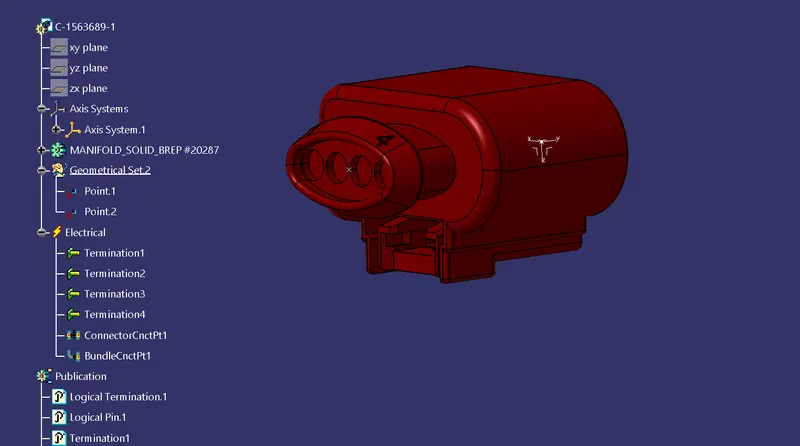
4-POLE CONNECTOR - C-1563689
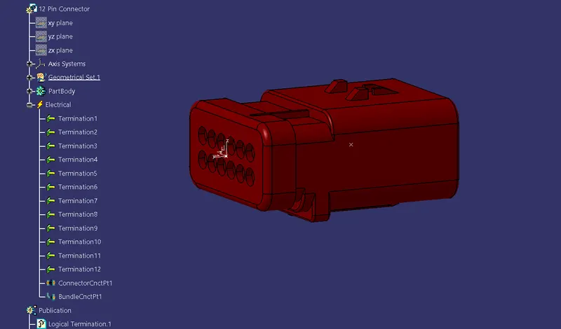
INTER-CONNECTION CONNECTOR - C-776438
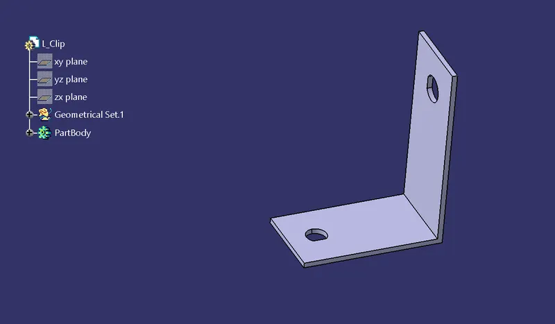
L-CLAMP
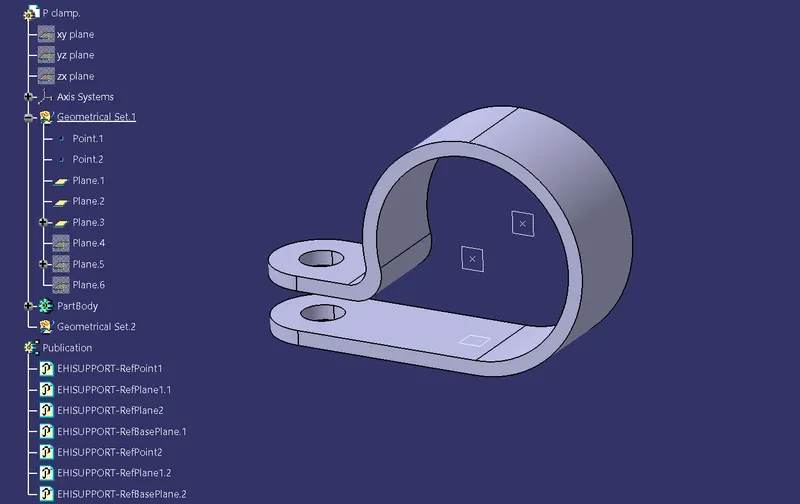
P-CLAMP
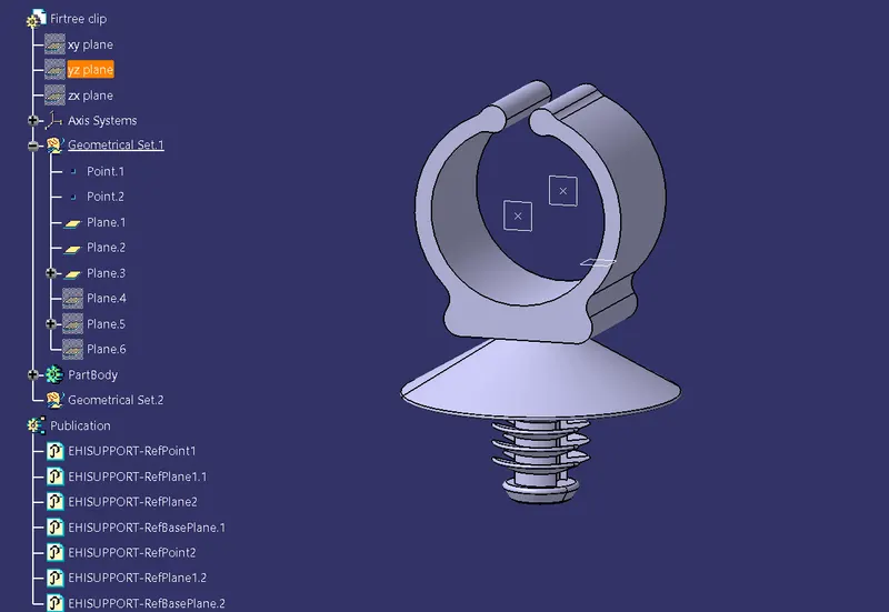
FIR TREE CLIPS
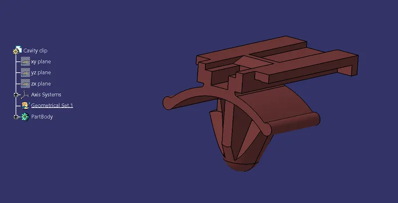
CAVITY CLIP
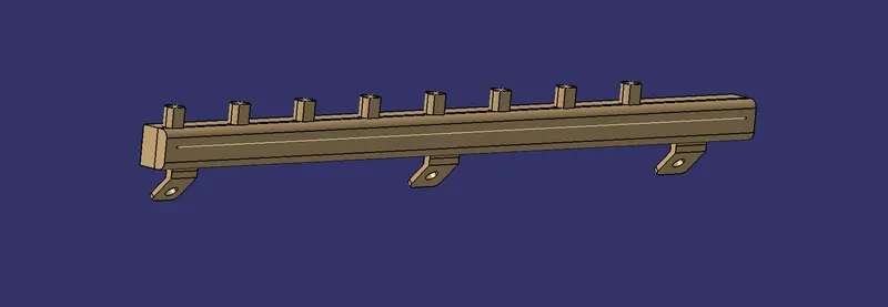
PLASTIC CHANNEL
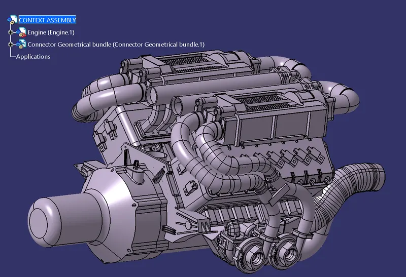
CREATE CONTEXT ASSEMBLY:
Create a new product file and insert the Engine CAD and Add a new product for Electrical Harness Geometrical Bundle for attaching the connectors, mounting parts, and plastic channel.
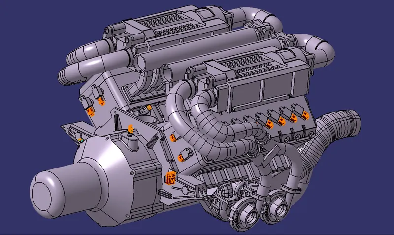
POSITION ALL THE CONNECTORS:
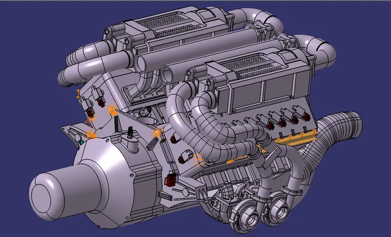
Insert the connectors in the file and position the connectors at the desired location using Manipulation, Snand ap tools in Assembly Design Workbench. 20 4-pole connectors, 3 2-pole connectors , and 1 12-pole inter-connection connector are positioned in the assembly.
POSITION ALL MOUNTING PARTS:
The 12-pole inter-connection connector is secured on the engine cover by an L-clamp and cavity clip. The wires run along through 2 P-clamps. 2 fir tree clips and two plastic channels on each side for protection.
MULTI-BRANCHING:
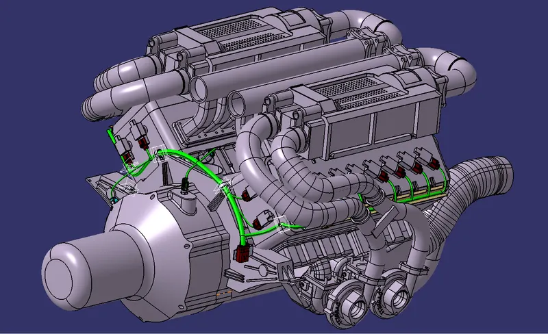
In the Electrical harness assembly workbench, the geometrical set is defined as a Geometrical bundle and the connectors are connected through multi-branching and providing slack to the wires wherever necessary. The wires run along through 2 P-clamps ans 2 fir tree clips and two plastic channels on each side for protection. The Diameter of the wires are provided based on the capacity of the bundles.
ELECTRICAL HARNESS PROTECTION:
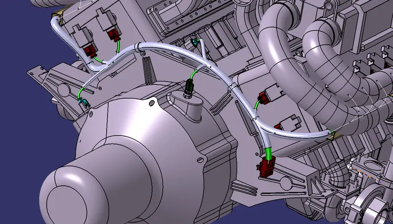
The wiring harness is protected by wrapping COT tubes around it. Minimal clearance is provided at necessary locations. Two plastic guide channels are also provided on each side for protection. 15mm and 20mm dia COT tubes are used to wrap the wiring harness.
ELECTRICAL CONTINUITY CHECK:
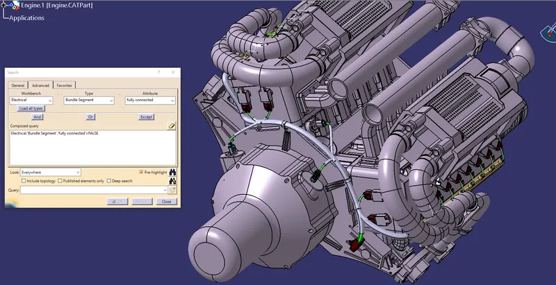
The Electrical continuity check is conducted to detect any errors in the wiring harness. This ensures that the entire geometrical bundle is connected properly.
FLATTENING OF GEOMETRICAL BUNDLE:
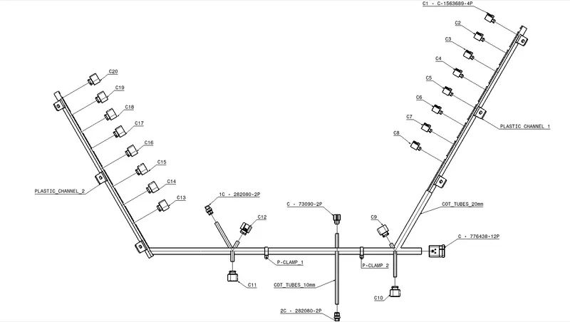
In the Electrical Flattening Harness workbench, the geometrical bundle is extracted, flattened, and manipulated in the desired orientation. Then the file is saved for the creation of a 2D drawing.
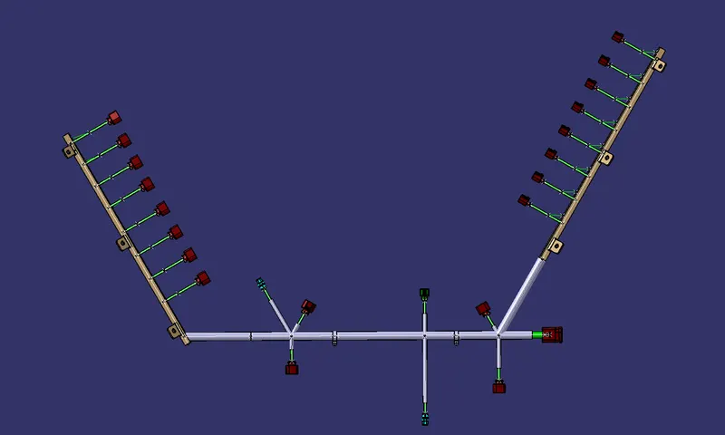
DRAWING CREATION:
Create a drawing file and extract the front view of the flattened assembly onto the drawing sheet. Define the drawing properties of the wiring harness sheet and save.