Project 1
The report for the given project is given below :-
- As soon as the part is ready for the mold design, the initial step would be analysing the draft,the draft must sufficient enough to eject the part feom the molds.if all the given drafts are sufficient enough we proceed further, if not can ask for the product team to given some draft where ever it is required and also the scaling of the part occurs with given shrinkage percentage.
- Next step would be creation of parting line, the analysis is required where to keep the parting line,and thats where the core and cavity will divided,after choosing it,the open countors must be closed with proper surface,to shut all the surfaces shutoff surfaces is used,finally if it shows in the green to it is separable quote,we should not move futher,hence the parting line is created and core and cavity is separated.
- The parting surface is created perpendicular to the part and normal to the parting line by using the command called ruled surface and lofted surface.later copy it for 1 instance to merge with core and cavity surfaces.knit all the surfaces and also with the core and cavity surfaces to get the final core and cavity with final surfaces. we can see the the final surface in the given below image.
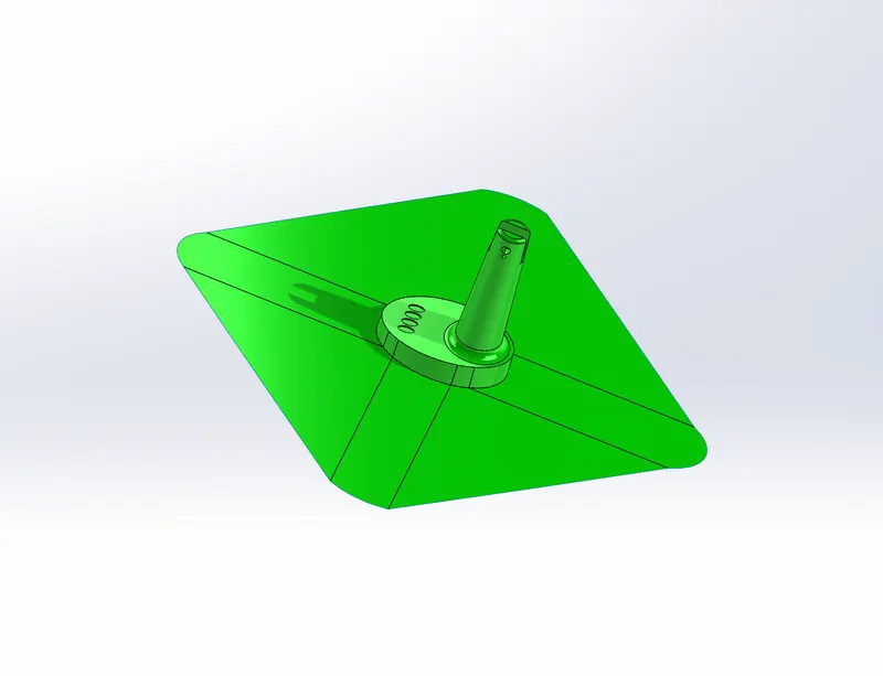
- Creation mold blocks depends on the part size,the size is decided accorting to the shape of the part,the core abd cavity blocks are created with sufficient enough space for sliders if any is required,and used the cut with surface command to cut the block and create the shape over it with respective parting surfaces.
- here i am providing the referance images which shows the complete picture of it.
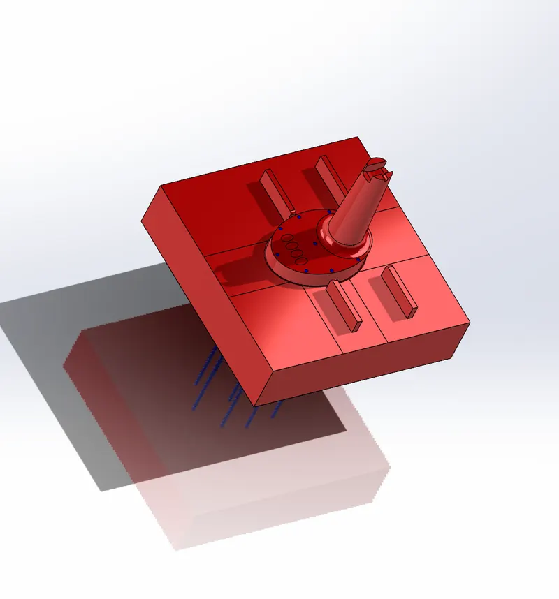
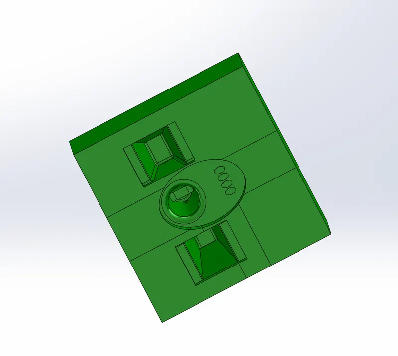
- After creating the mold blocks need to analyse the undercuts which forms while ejecting the part from the mold,if any unercuts we must be avoided to include them in core or cavity blocks,if any undercuts we must be providing sliders to over the effect of undercuts.
- We draw a sketch which can cut the body and we can remeke the shape of the block to reduce the material usage and look wise by using the split command.
- Once we get the final shape of the slider we make a copy of the slider solid for 1 instance ,and substract the one duplicate body from the main body and save the original into a new part and save it for to import if any further need.
- Reapeat the process for no of sliders, and follow the smae procedure and save them in the order.i have attached the images to refer them.
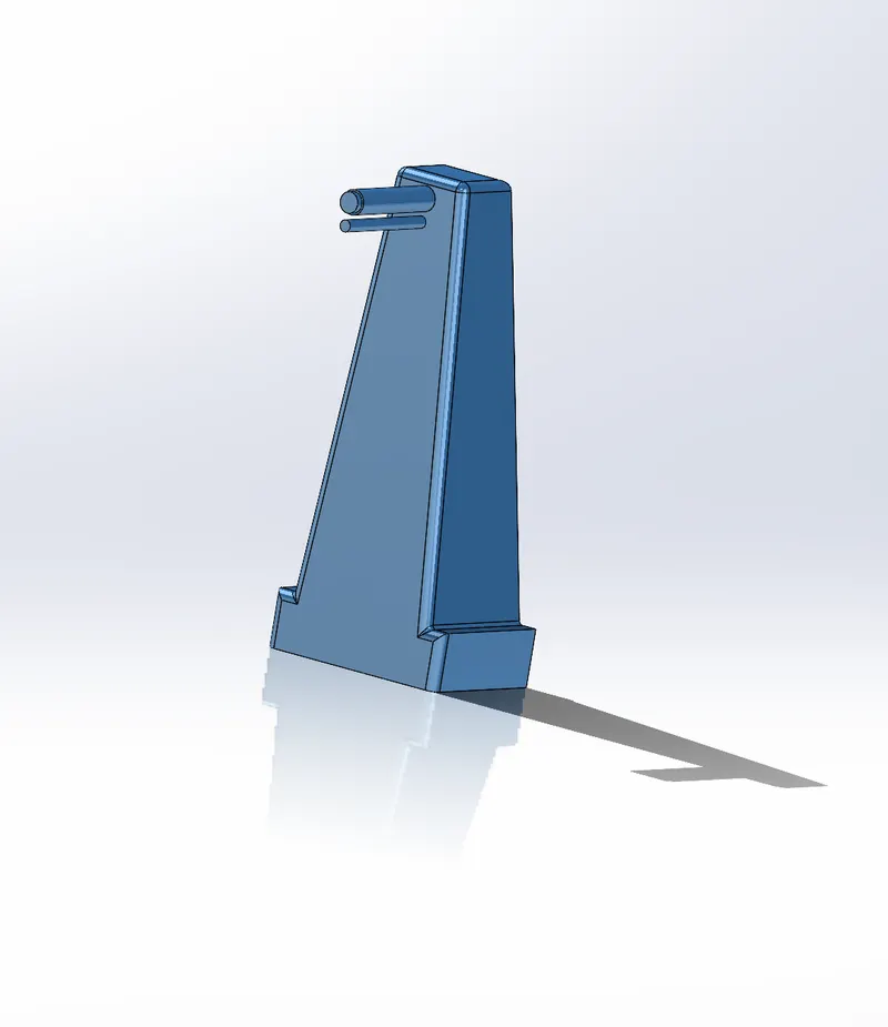
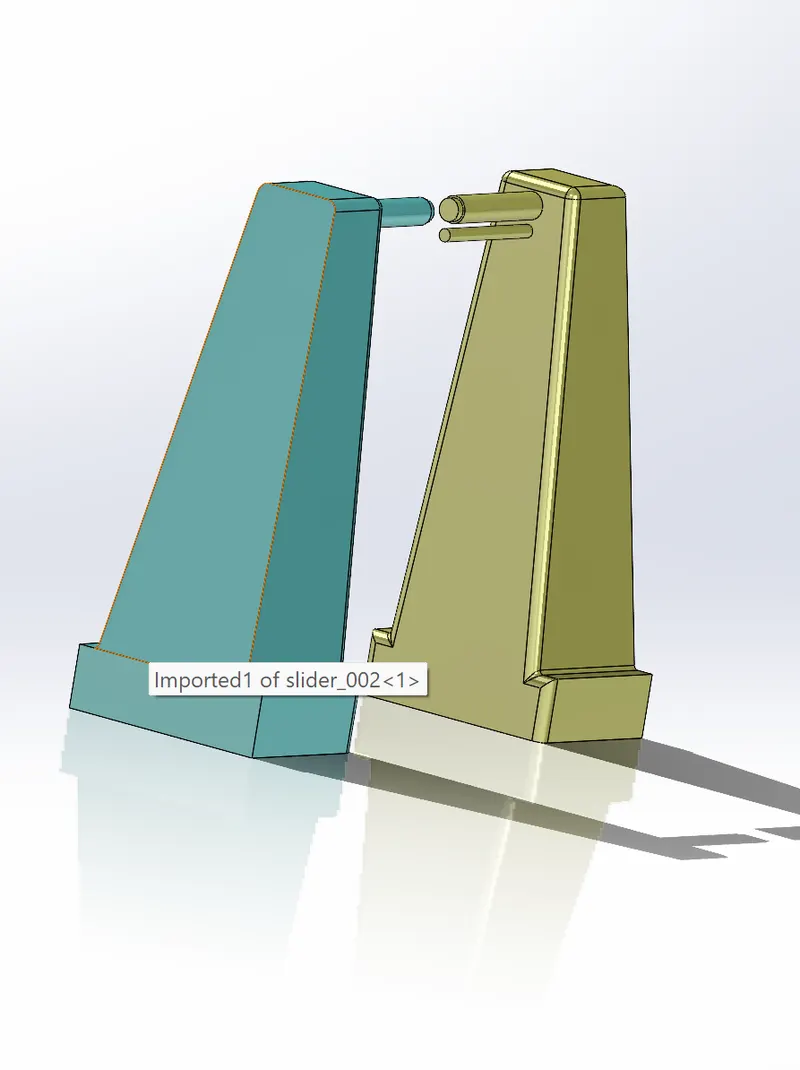
- The next step would be removing the material of core and cavity side to mathe the profile of slider into the core and cavity,this removal can takes place by substracting the sliders from the actual blocks by using combine command.
- Finally some addition and substraction of material ocuurs to get required shape of the core and cavity,and also used move face command to make a path for guidance for the slider to make a move after injection occurs.
- The ejection pins are aslo created on the core side by following the standards which can seen on the given image below.
