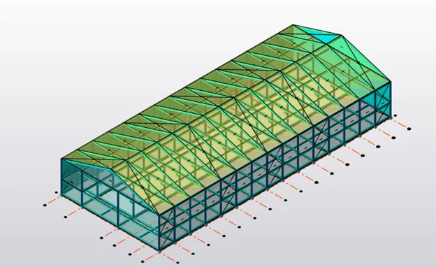
Project 1
Project 1:
Analyze and design a steel building to 10T CRANE as per IS standard code in TEKLA STRUCTURAL DESIGNER. Refer to the attached plan and elevation. Provide bracings and moment connection for lateral stability.
Consider dead, live, equipment, and wind loading. Consider the brick wall loading for 150mm thick and 1.5 KN per sq m for wall and roof cladding.
Assume wind loading basic speed as 39m/s
Report of each member to be generated and extract drawings of structural plans from the software
AIM: To analyse and design the given steel building according to the IS standard codes.
Procedure:
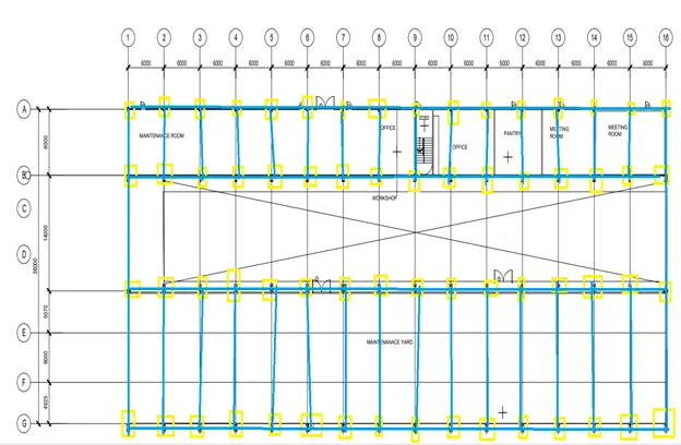
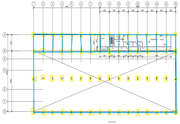
- First, we have to create a rough sketch of columns and beams using paint.
GROUND FLOOR
FIRST FLOOR
- After a rough sketch, a new Tekla file is opened and saved as Project-1
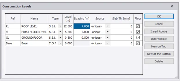
- Now create construction levels according to the given section plan.
Model tab-> construction level-> Base level (GF)- 0.5m -> First level(FF)- 5m -> Roof Level (RL) -7m.
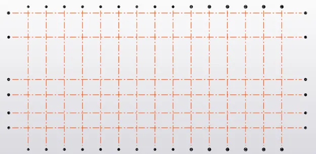
- After this, we have to go to the base level and create the grids according to the dimensions.
- Model panel-> grid line-> pick point-> pick another point
- To create another grid use quick parallel-> Distance at which the grid to be created.
- Like the above procedure create all the grids using parallel and perpendicular grids.
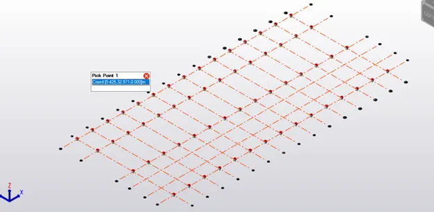
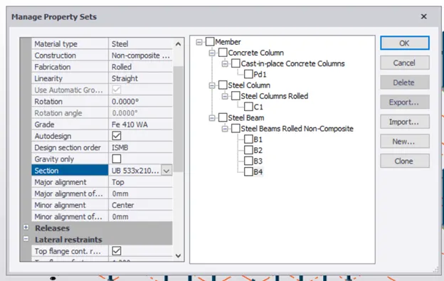
- After this create the RC columns till the base level of property 600x600 and M30.
- Property sets-> member-> concrete column -> 800x800 section -> M30 Grade
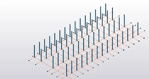
- Then add steel column from Ground level to roof level
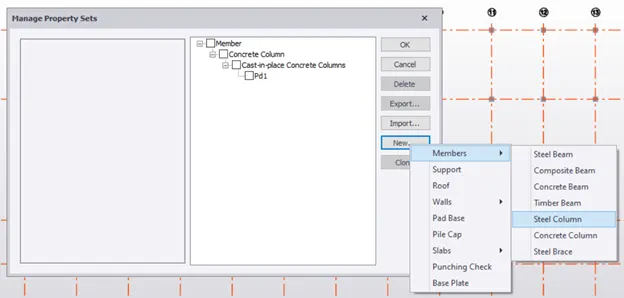
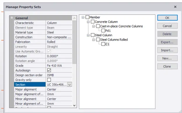
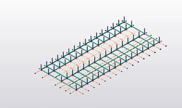
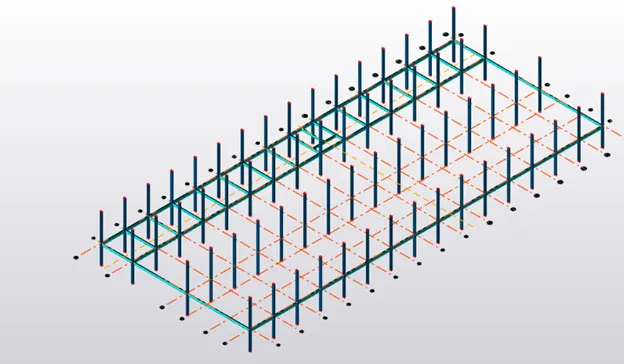
- After the creation of columns now create Primary & secondary beams steel beams in the ground, first & roof levels as required.
GROUND FLOOR
FIRST FLOOR
ROOF LEVEL
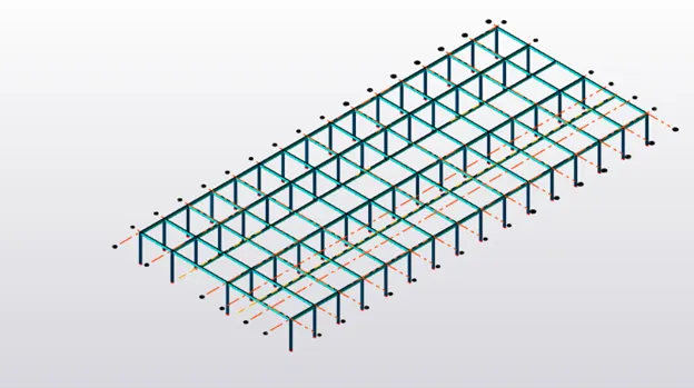
- Now in structure 3D create frames for each grid.
- Model tab-> Frames-> Select each grid.
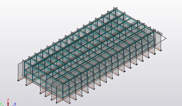
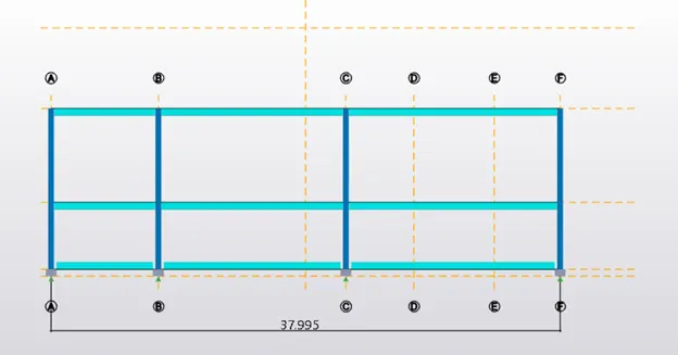
- Open frame 1
- Create a construction line with reference to the section view to create rafter beams.
- Create rafter beams property in property sets and model them in frame view.
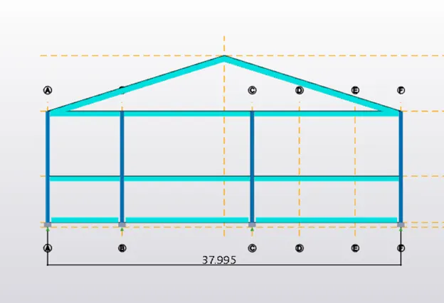
- Now open 3D view and copy the rafters to other gids also to form roof.
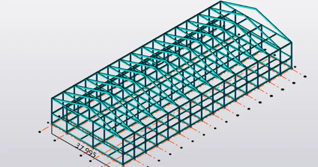
- Now create the ridge beam at the top of roof in 3D view.
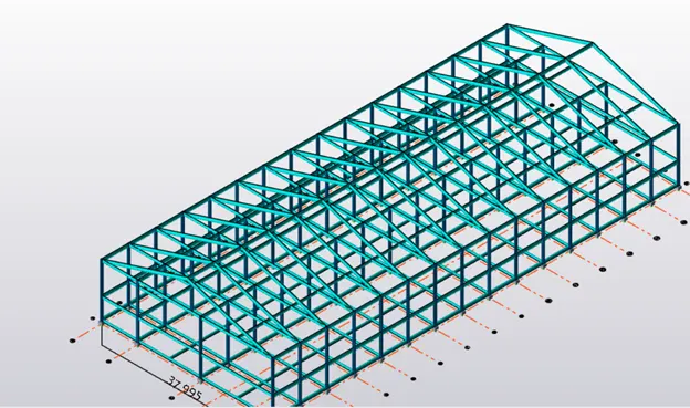
- Now add bracings on frame A & F and on the roof in 3D view.
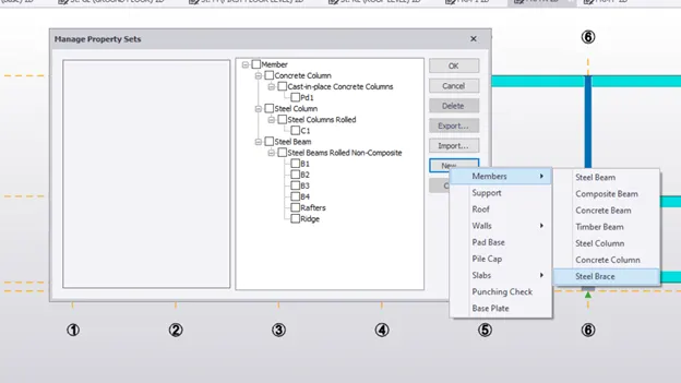
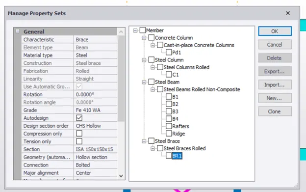
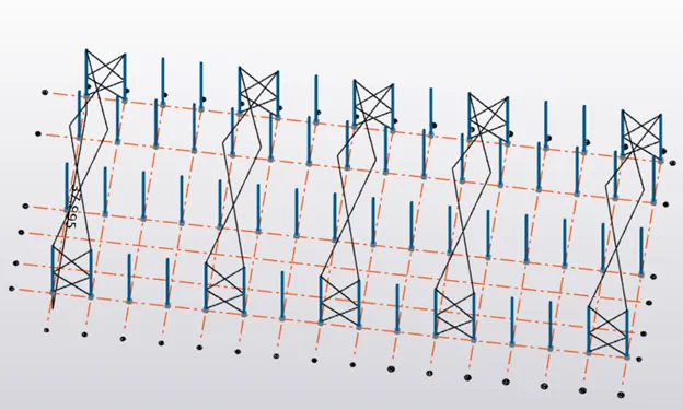
- As of now, we had been modeled columns, beams, and bracings.
- Next, we have to add slabs according to the dimensions.
- If L/B <2 then take two-way slab and if L/B > = 2 take as one-way slab.
GROUND FLOOR
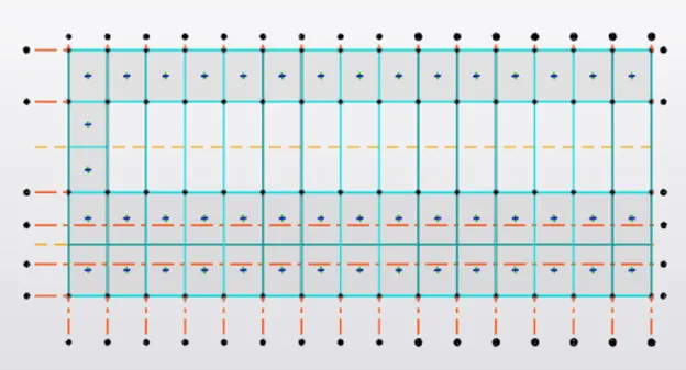
FIRST FLOOR
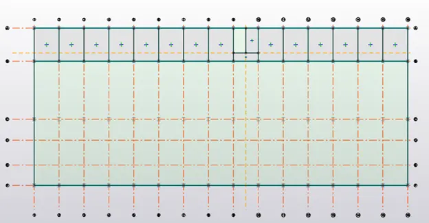
ROOF LEVEL
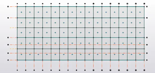
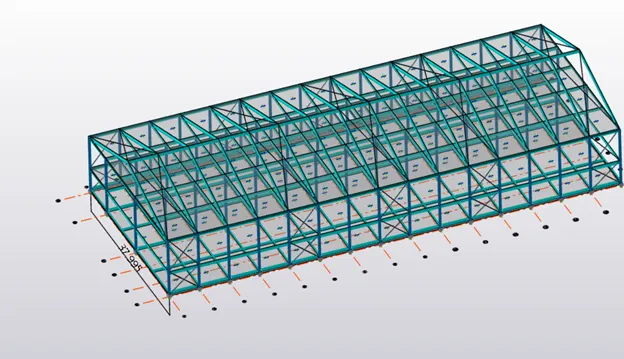
- Now after the creation of slab on all levels we have to create wall and roof panels
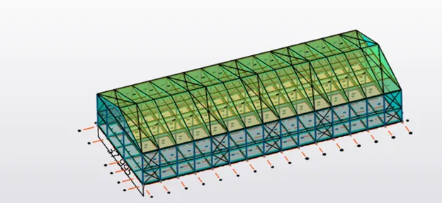
- Till now we had done with modeling of the structure
- Now we have to add loads that are dead, live, and crane loads in the model.
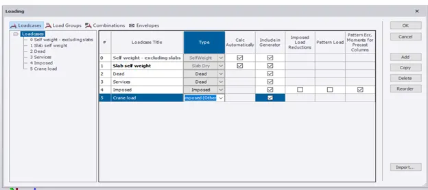
- First, we want to calculate the loads manually as per IS 875 Part 1 & 2.
- Manual dead load calculations
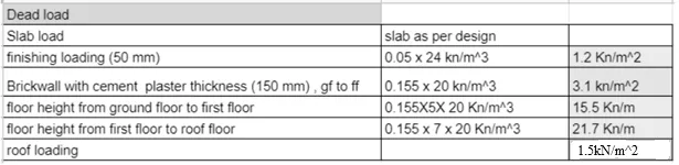
- Now apply the Finishing load of 1.2kN/m^2 to the model.
- Load case as dead load -> area load-> 1.2
-
Finishing Load
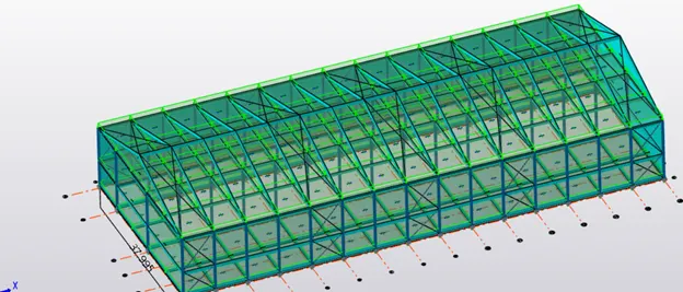
- After application of finish load to GF, FF & RL
- Now have to apply dead load to GF of 15.5kN/m.
- Ground Floor-> Dead load-> Full UDL-> 15.5
GF(Brick wall Load)
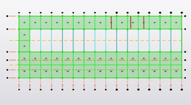
- Now apply the full UDL dead load of 21.7 kN/m on the First floor.
FF(Brick Wall Loading)
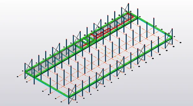
- The roof area load is 1.2kN/m^2.
RL(Roof area load)
- Now apply the area load of 1.5kN/m^2 in the roof level.
- After application of dead load the 3D view is like below:
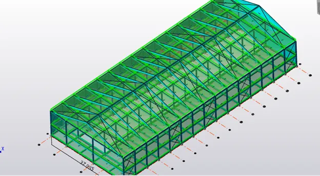
- Live loads according to the IS 875 Part2 and according to the sketch are as follows:
Live Loads:
Maintenance room = 2.5kN/m^2
Office = 2.5kN/m^2
Pantry = 3kN/m^2
Meeting room = 5kN/m^2
Workshop = 10kN.m^2
Maintenance yard= 2.5kN/m^2
Staircase = 5kN/m^2
Flat roof without access= 0.75kN/m^2
Toilet = 2kN/m^2
Conference room = 5KN/m^2
Corridors = 5kN/m^2
- Now apply the live load as area load in the ground, first floor, and roof according to the IS code by selecting Imposed load in the loading list.
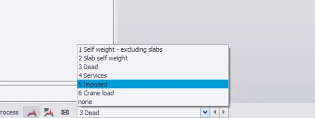
Ground Floor
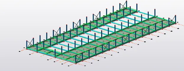
First Floor
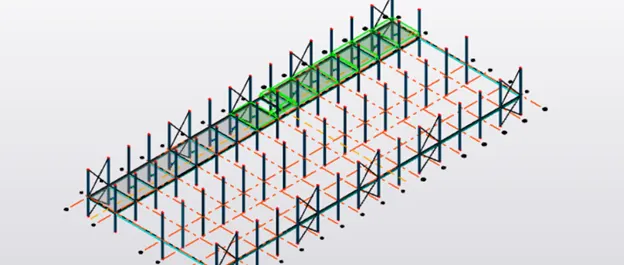
Roof level
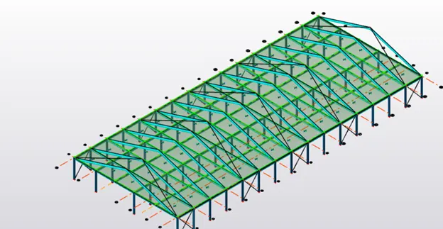
- 3D view of Imposed or live load
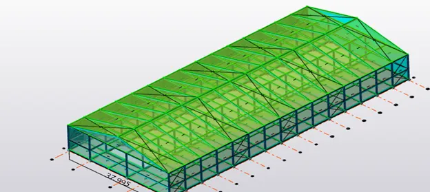
- After dead and live loads moving to Wind Load. So we have to calculate the Wind load manually as per IS 875 Part 3.
WIND LOAD CALCULATIONS
- Vb = 39m/s
- Life of structure = 50years
- Terrain category =2
- Class of structure = A
- L = 90m
- W = 38m
- H = 12m
- L/W = 36(>1.5,<4)
- H/W = 31 (<0.5)
- From TABLE 5 of IS 875 Part 3
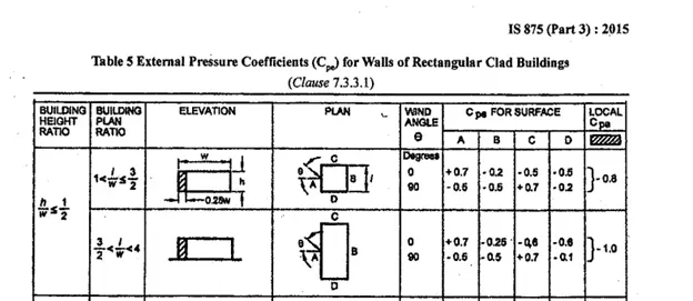
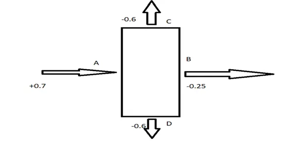
- From table 1 K1 = 0
- From table 2 K2 = 02 (by Interpolation)
- From caluse 6.3.3.1 K3 = 1.0
- From caluse 6.3.4 K4 = 1.15 for Industrial Buildings.
- Design Wind Speed, Vz = VbxK1xK2xK3xK4
= 39x1x1.02x1x1.15
= 45.747m/s
- Design Wind Pressure Pz = 0.6xVz^2
= 0.6x (45.747)^2= 1255.67N/m^2
= 1.25 kN/m^2
- According to Clause 7.3.2.2 Internal pressure coefficient is taken as +0.7 and -0.7 (More than 20% openings)
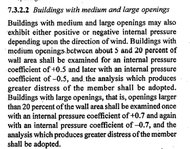
- The wind is calculated both in X and Y directions and taking the A & B faces in the Y direction and C&D faces in the X-direction.
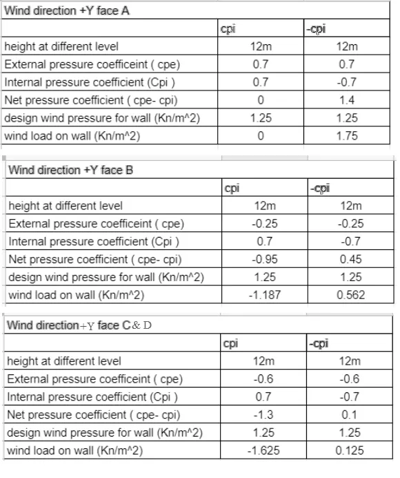
- All the wind load values are multiplied by 1.05 as it should be calculated for 12m height (K2 value=1.05).
- First create wind load cases in load cases as +Y+Cpi, +Y-Cpi, -y+Cpi, -y-Cpi, +x+Cpi, +x-Cpi, -X+Cpi, -X-Cpi.
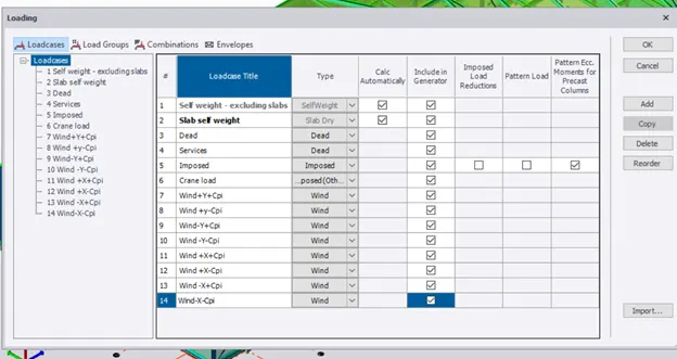
- Now select the wind load cases respectively and apply them in the respective frame.
+Y+Cpi
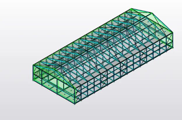
+Y-Cpi
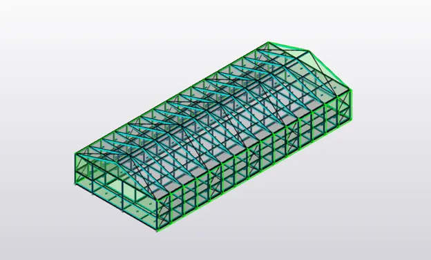
-Y+Cpi
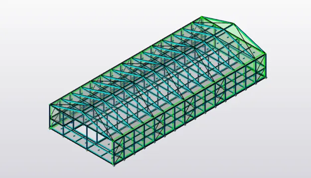
-Y-Cpi
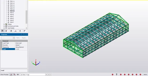
- Like the same way remaining wind load cases are also to be assigned.
- The same procedure is followed for Roof also.
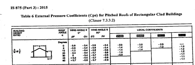
- H/W = 0.31
- Slope = 18 Degrees
According to the IS code 875 TABLE 6
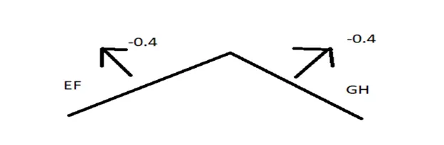
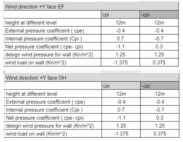
- As discussed above, now these loads are multiplied by 1.05 and applied to the model.
+Y+Cpi
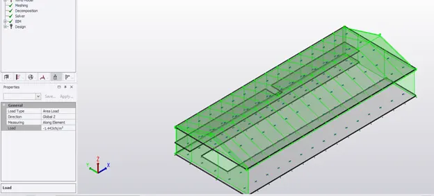
- Similarly, we have to apply all wind loads on the roof as in the same procedure we had done before.
- As of now the wind load calculation and assigning it to the model had been completed.
- Next Crane load calculation has to be done.
- Before that, we have to model the Brackets on the first floor to carry the crane load.
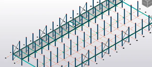
CRANE LOAD CALCULATIONS
- Crane Capacity = 100kN
- Weight of crab = 35kN
- Weight of Crane = 160kN
- Max Hook Approach = 1m
- Wheel Base = 3m
- Distance Between c/c Gantry rail= 20m
- Distance Between c/c Gantry columns= 6m
Maximum Wheel Load
Maximum point load on the crane = crane capacity + weight of the crab= 100 + 35 = 135
Self weight of the crane = 160kN
UDL = 160/20 = 8kN
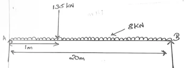
To get end reactions, Take the moment about B
Rax20 – 135x19 – 8x20x10 = 0
Ra = 208.25kN
Taking moment at A
Rb x 20- 135x1 -8x20x10 = 0
Rb = 86.75kN
Maximum Wheel load on each wheel = Ra/2 = 104.125kN
MAXIMUM BENDING MOMENT:
Assume the self-weight of gantry girder = 1.5kN/m
Assume self-weight of rail = 0.3kN/m
Total dead load = 0.3+1.5 = 1.8kN/m
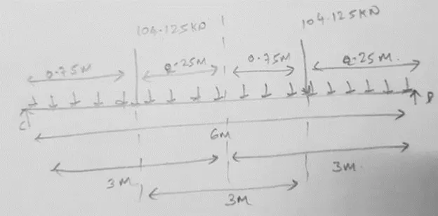
AT C
Rd x6-104.125(0.75+3)-104.125x0.75= 0
Rd = 78.09kN
AT D
Rcx6- 104.125(2.25+3)- 104.125x2.225= 0
Rc = 130.15kN
Rc + Rd = 208.25kN
BM under a wheel due to live load = 78.09x2 = 156.18kNm
BM due to impact = 0.10x 15.18 = 15.618 kNm
Total BM = 171.79kNm
BM due to dead load = WL^2/8 = 1.8 x 6x6/8 = 8.1 kNm
Maximum BM = 171.79+8.1 = 179.89kNm
MAXIMUM SHEAR FORCE
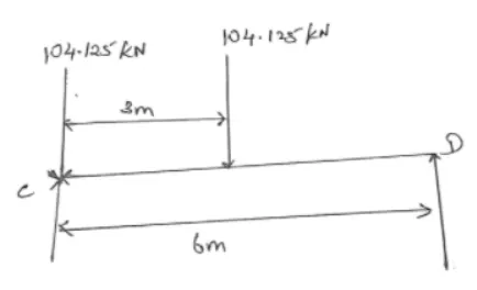
AT D
Rc x 6 -104.125x 6 -104.125x3= 0
Rc = 156.18
Maximum shear fore due to wheel load is 156.18kN
LATERAL FORCES:
Lateral force which is traverse to rail = 5% of weight of the crab and weight lifted
= 0.05x135
= 6.75kN
Lateral force on each wheel = 3.375kN
Maximum horizontal reaction at C
= lateral force x reaction at C due to vertical load / max wheel load due to vertical load
= 3.375x130.15/104.125
= 4.21kN
Maximum horizontal reaction at D
= lateral force x reaction at D due to vertical load / max wheel load due to vertical load
= 3.375x 78.09/104.125
= 2.53kN
4.21+2.53= 6.75kN
BM due to lateral load = 3.375x 15.18/104.125 = 5.06kNm
- Now, these loads are to be applied on the model as point load that too nodal load.
- First, select the crane load from the loading list.
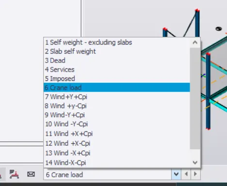
- Point load-> nodal load-> x= 4.21-> y= 2.53-> z= 156.81
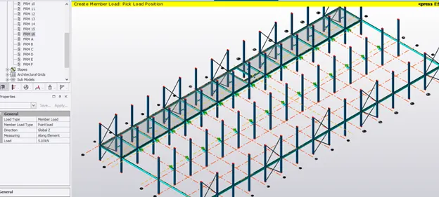
Analysis of the Structure:
- After applying all loads, we have to do an analysis.
- Before the analysis, we have to validate the structure and if any error had occurred we have to rectify it if no error had been encountered then we can move to analysis.
- Analysis-> first-order analysis.
- After the analysis had been done if there are any errors you have to check them and encounter them by changing the sizes or implementing a decrease in a span if there is more span and do according to the error.
- If the seismic load has to be given then use seismic wizard.
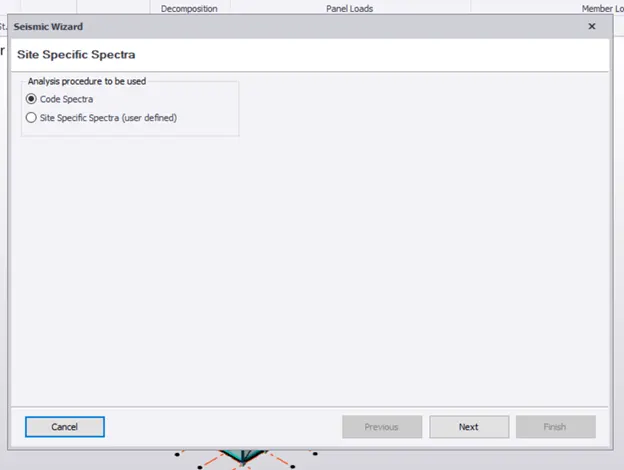
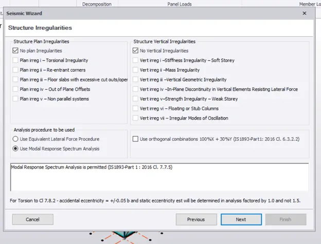

- Then finally seismic load will automatically be generated in load cases
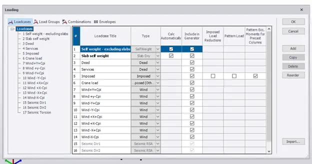
- Finally, do the analysis again and rectify the errors if any.
RESULT:
Hence the Analysis had been done to the given Steel structure
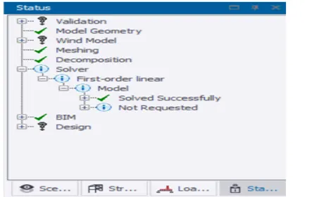
Structure