Project 1
1. Design a battery pack for a car roughly 150 Kw with 120 V. Use 3500 mAh 3.6V nominal NMC chemistry cell.
a. Design the battery pack configuration.
b. Draw the BMS topology for this battery pack.
- The Master & Slave topology more no of slave each slave consist of minimum 18 cells of Nominal voltage of 3.6 V.
- So , for making battery pack of 120 V we have to take a 3 no of slave of
Slave No 1 : 12 Cells (each of 3.6 V) = 43.2 V
Salve No 2 : 12 Cells (each of 3.6 V) = 43.2 V
Salve No 3 : 10 Cells (each of 3.6 V) = 36 V
- Now addition of Slaves =
Slave No 1 + Slave No 2 + Salve No 3
= 43.2 V + 43.2 V + 36 V
=122.4 V i.e. nearly equal to , 120 V.
- Given - :
Power = 150Kw
Voltage = 120V
Energy of Battery = 3.5Ah
Nominal Voltage = 3.6V
- To Find - :
Cells in Series ?
Cells in Parallel ?
- Solution - :
Cells in Series = Total Voltage / Nominal Voltage
= 120 / 3.6
= 33.33
≅ 34
- Therefore 34 cells are required in series.
Cells in Parallel = Total Current / SIngle Cell Capacity
= P = V * I
I = P / V
= 150000 / 120
= 1250
I = 1250A
Cells in Parallel = 1250 / 3.5
= 357.14
≅ 358
- Therefore 358 cells are required in parallel.
1.B. Draw the BMS topology for this battery pack - :
2. Build a 3S2P battery pack configuration with generic battery block using Matlab/Simulink - :
- Given - :
Maximum Vtg = 4.2V
Nominal Vtg = 3.7V
Energy of battery = 3Ah
- 3S2P BAttery pack configuartion using simulink model :-
- To connect batteries in 3S2P configuration in simulink. that is 3 cells should be connected in series & 2cells are connected in parallel.
- Total no. of cells in battery pack = No of cells connected in series * No of cells connected in parellel.
= 3*2
= 6 cells.
- Step :1 Arrangement of 6 cells - :
- Step:2 Series Connection - :
- Fig shows the battery connected in Serieserminal of battery combination.Batteries are connected from terminal to terminal in a way that
positive(+) terminal of one battery is connected with negetive (-) terminal of the battery and negetive (-) yerminal is connected with the
positive terminal (+) of other battery.
- Step 3 Parallel connection - :
- The fig shows batteries connected in parallel. for parallel connection , batteris are connected from terminals to same terminal of other
battery i.e. positive (+) terminal of battery is connectrd to positive (+) terminal of other battery & Negetive (-) terminal of battery is
connectrd to negetive (-) terminal of other battery.
- Step :4 Simulink Model - :
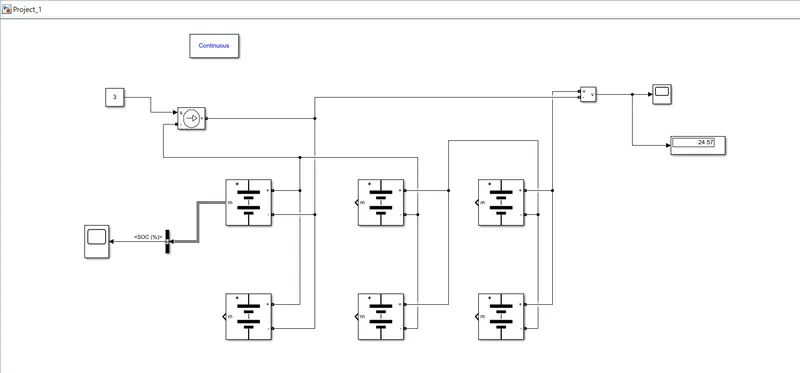
- The parameter given inside the battery is given as - :
| Sr.No | Battery Parameters | Value |
| 1 | Nominal Voltage of cell | 3.7 V |
| 2 | Rated capacity of a cell | 3 Ah |
| 3 | Maximum voltage of a cell | 4.2 V |
- Nominal voltage of the batery pack = no of cells in series * Nominal voltage of cell
= 3 * 3.7 V
= 11.1 V
- Rated capacity of the battery pack = no of cell in parallel * Rated capacity of a cell
= 2 * 3 Ah
= 6 Ah
- The model is for an 11.1 V 3 Ah battery.
- Single battery output for SOC - :
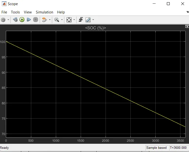
- Plot No 1 - :
- The SOC (state of charge) is started to reduce from 100% to 0% corresponding to the load given.
- It discharges after 1hr which is equal to 3600sec.
- The overall output voltage of the battery pack is given as - :
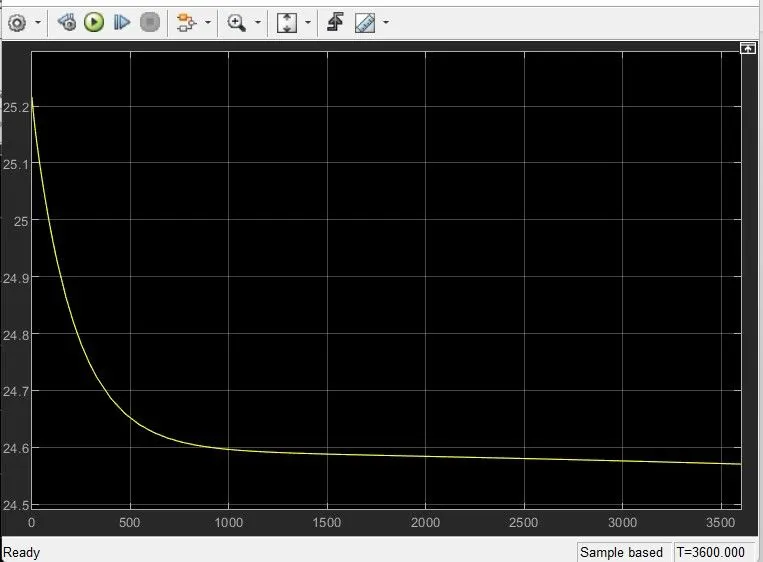
- Overall voltage of the battery pack = maximum volatge of the battery * no cells in series
= 4.2 * 3
= 12.6 V