Project 1
* Load the Project1 folder as the Current Folder in Matlab
* Run the “Project1_InitFile.m” Matlab script.
* The data which load as a program, it will take as an input program of the vehicles which is used for Post-processing of the Simulation by using the Simulink Model which is already built
* Drive Cycle selection is also done from here by choosing the variable in it eg:1 is for UDDS, 2 is for HWFET, and 3 is for FTP.
* Before running the Simulink model we have to induce inputs variables to the workspace to use by the Simulink model
Engine model
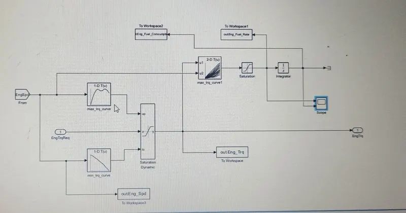
Based on the Engine Speed, the required torque from the controller is between Max torque and Min Torque curve and it will transfer the Engine Torque to the Transmission Block.
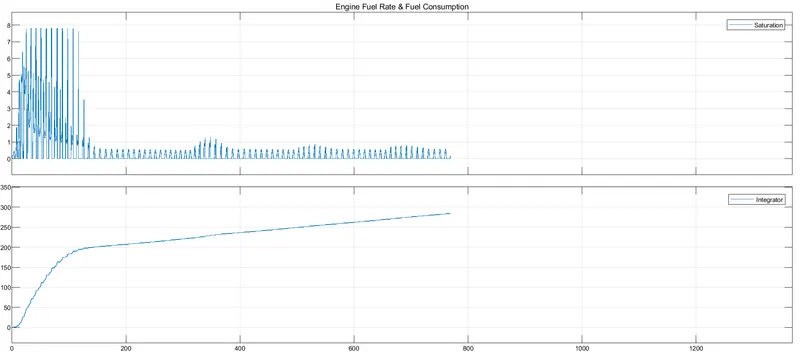
The 2D lookup table is used to calculate the fuel rate and is then integrated to find the fuel consumption rate of the engine, by using the engine speed and engine torque.
By using the 'To Workspace' block command the estimated fuel flow rate, fuel consumption, engine torque, and engine speed is been passed to the workspace of MATLAB.
To see the output of Engine Flow rate and Fuel Consumption is been scoped.
Vehicle dynamics model
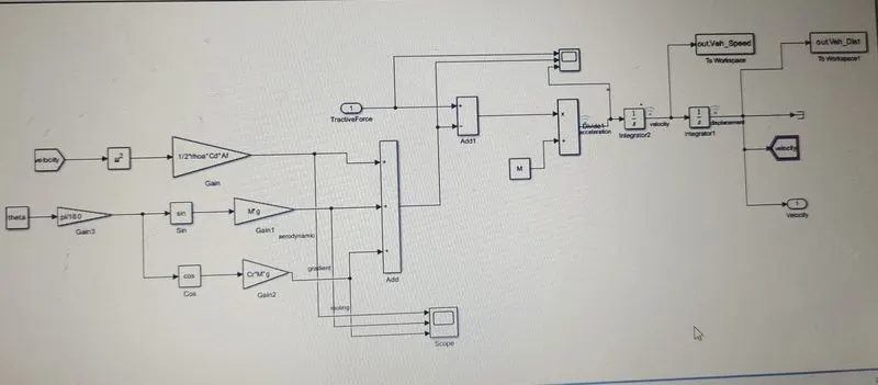
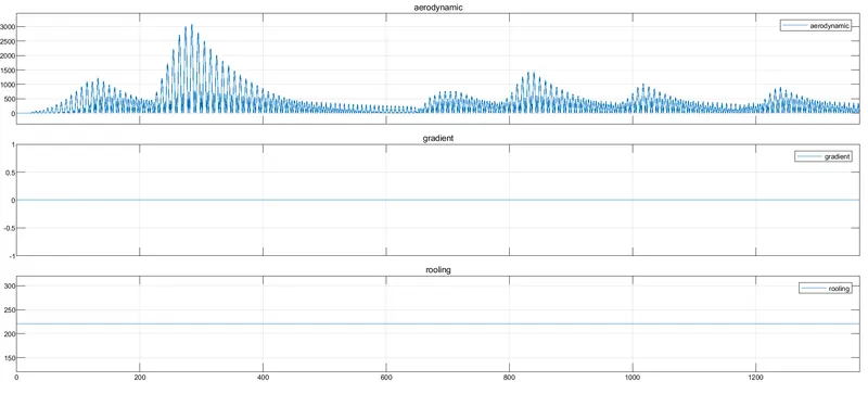
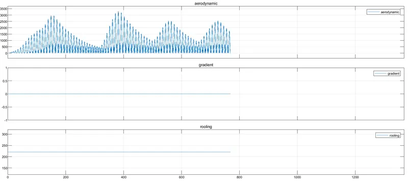
This block consists of the longitudinal dynamics of the vehicle which consists of Aerodynamics force, Rolling Resistance Force, Grade Force etc..,
Formulas used:
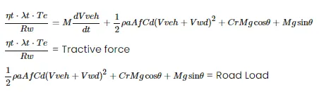
where
rhoa - Air Density
Af - Frontal Area
Cd-Drag Coefficient
M - mass of a vehicle
g - Acceleration due to gravitational force
`theta` - Slope angle
These variables have already been preloaded to the workspace using a MATLAB script
USSD
It stands for Urban Dynamometer Driving Schedule and refers to a United States Environmental Protection Agency-mandated dynamometer test on fuel economy that represents city driving conditions and is used for light-duty vehicle testing.
Though it was originally created as a reference point for fossil-fueled vehicles, it is also used to give estimates on how many miles an electric vehicle will travel on a single charge
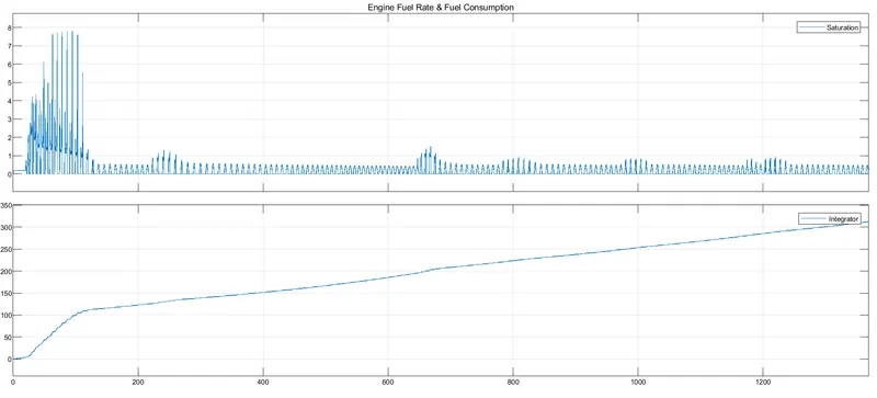
engine fuel rate & fuel consumption plot
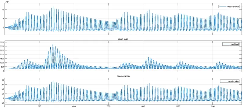
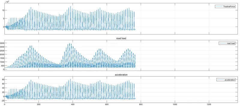
Tractive force, road laod & acceleration
different forces
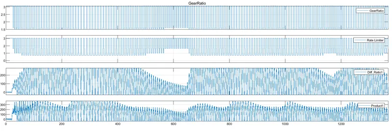
Gear ratio, transmission input & output speed
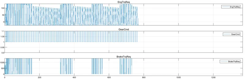
control signal
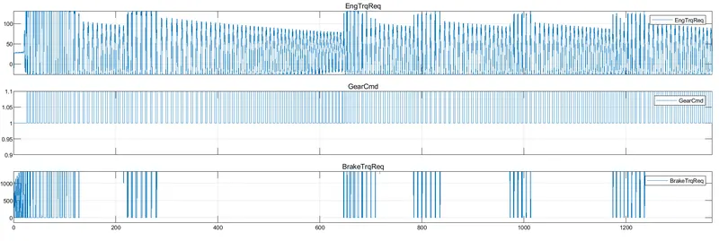
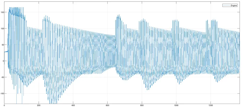
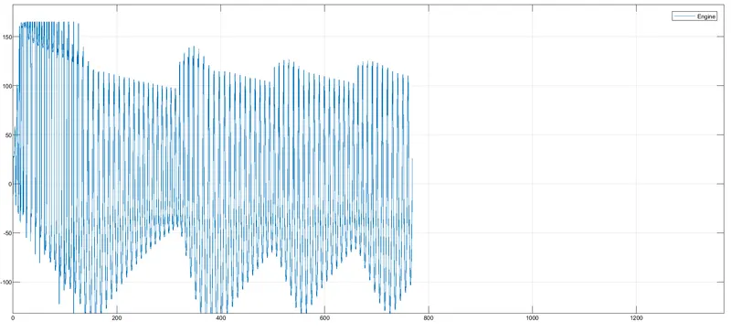
Engine torque
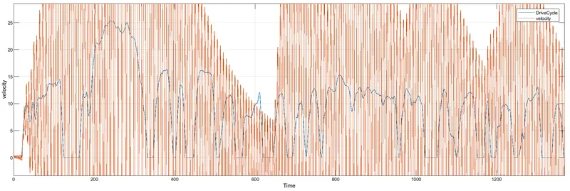
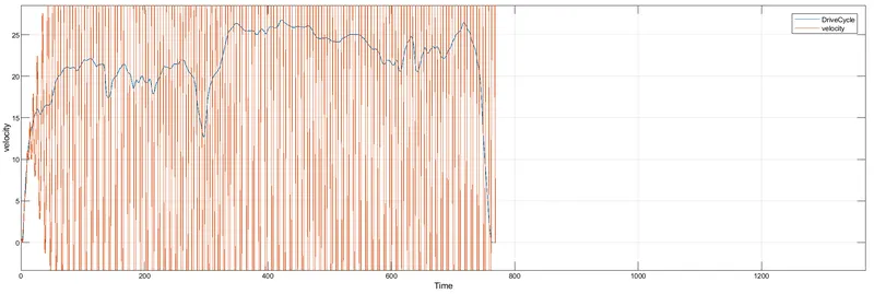
Drive cycle & actual velocity
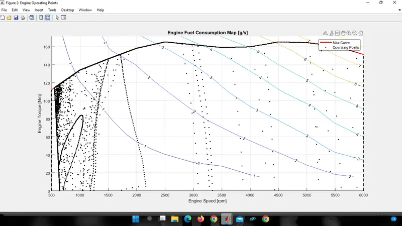
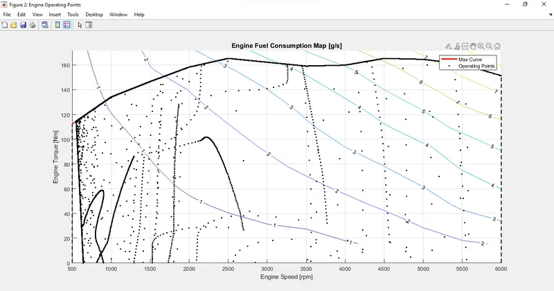
engine operating pints on engine fuel map
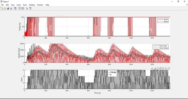
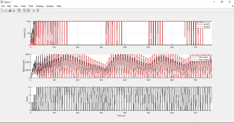
accelerator & brake pedal, gear command, vehicle desired and actual speed , vehicle distance
HWFET
The Highway Fuel Economy Test (HWFET or HFET) cycle is a chassis dynamometer driving schedule developed by the US EPA for the determination of fuel economy of light-duty vehicles [40 CFR 600, subpart B]. The HWFET is used to determine the highway fuel economy rating, while the city rating is based on the FTP-75 test.
Engine fuel rate & fuel consumption.
Different forces
Tractive force, road load & acceleration.
control signal
Drive cycle & velocity
Engine torque
engine operating pints on engine fuel map
accelerator & brake pedal, gear command, vehicle desired and actual speed , vehicle distance
Tabulate the fuel economy numbers (kmpl) for UDDS and HWFET cycles. This forms the baseline numbers for comparing with the future hybrid version.
Plot the time trace for engine, transmission input, transmission output, and wheel speed on one plot.
Using subplots, plot engine torque, power, fuel rate, and consumption.
Using subplots, plot accelerator and brake pedal, gear command, vehicle desired and actual speed, and vehicle distance.
Plot the engine operating points on the engine fuel map.
These plots describes the vehicle behavior throughout the drive cycle.
Generate the plots for both drive cycles