Project 1
DESIGN AND ANALYSIS OF BRIDGE WITH DEAD LOAD,IRS LIVE LOAD,WIND LOAD,EARTH PRESSURE LOAD AND SEISMIC LOAD FOR AHMEDABAD METRO RAIL PROJECT
AIM
To Design and analyse a bridge with Dead load,IRS Live load,Earth pressure load,Wind load and seismic load using STAAD Pro. Software.
INTRODUCTION
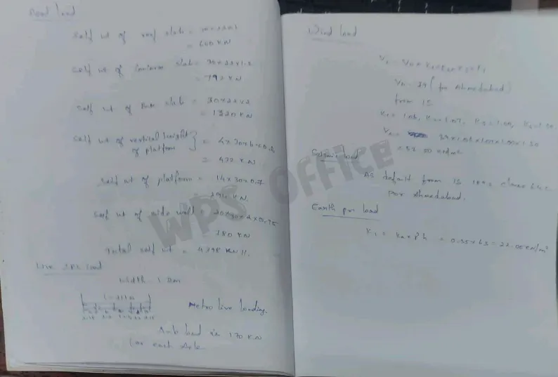
As per the given data with reference of IS 875 PART 3 2015 and IS 1893 2016 along with standard formulas the required load data is being calculated manually
PROCEDURE
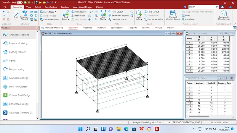
Step 1 - Create Nodes by entering the corresponding X/Y/Z values in the Node table for Creation of geometry for bridge structure with elements such as Beams,Deck slab,Side walls etc.,
Step 2 - After creating the nodes connect those nodes with add beam option and add plates option.
Step 3 - Then Click specification tab and click fixed support tab
Step 4 - After that in create support dialog box add fixed support for all the 4 corners in the geometry using assign for selected nodes option.
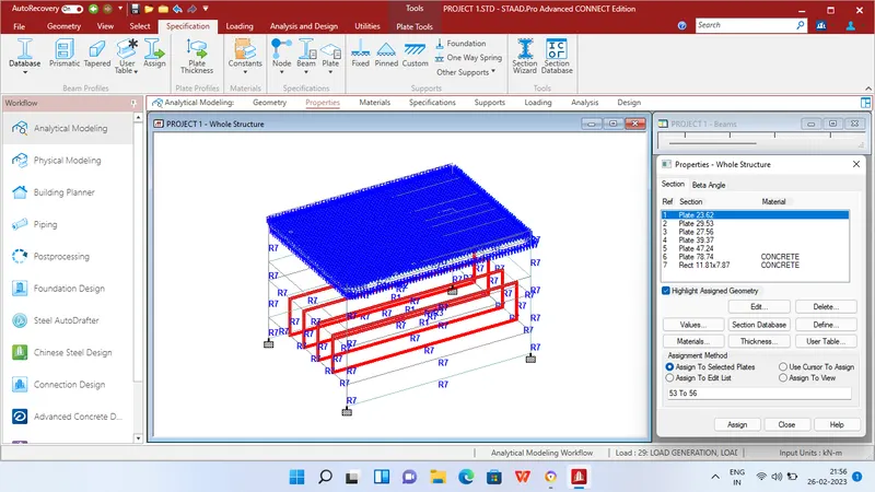
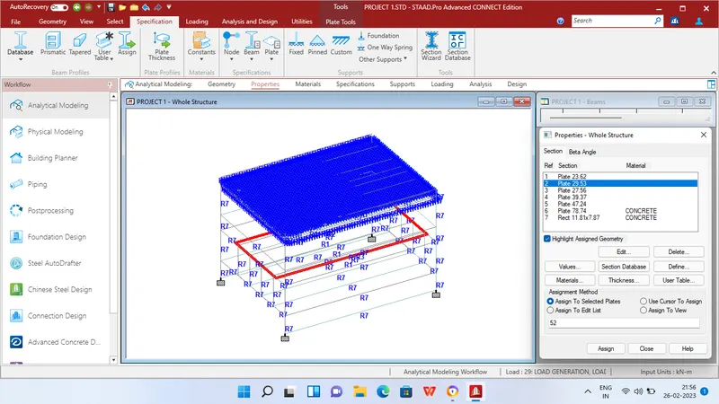
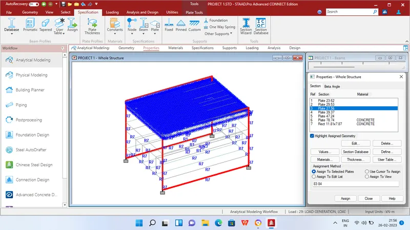
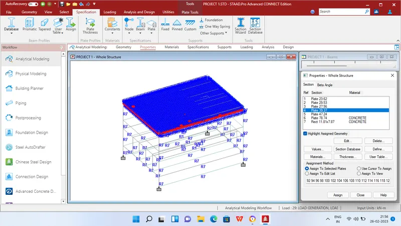
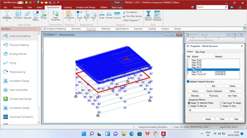
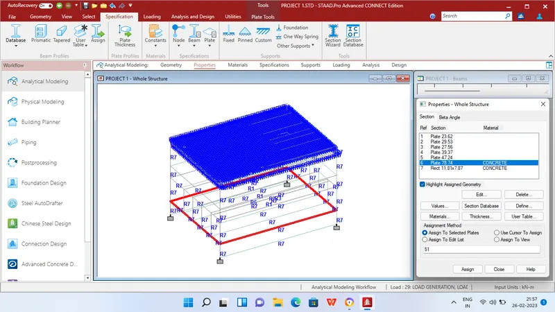
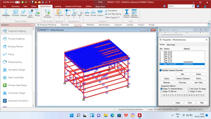
Step 5 - Then in Properties tab click Prismatic and add the property for beams and varied thickness for slabs as below
2m Thick for base slab
1.2m Thick for concorse slab
1m Thick for roof slab
0.75m Thick for side walls
0.7m Thick for Platform
0.6m Thick for vertical support of platforms
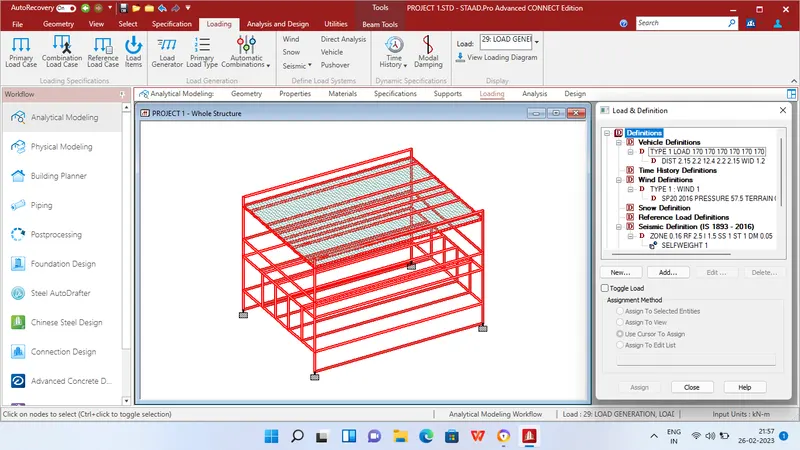
Step 6 - After adding the properties Define vehicle load for IRS Live loading,Wind load for Ahmedabad zone and seismic load as well for Ahmedabad zone.
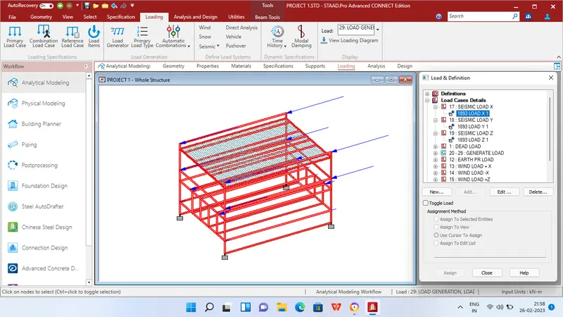
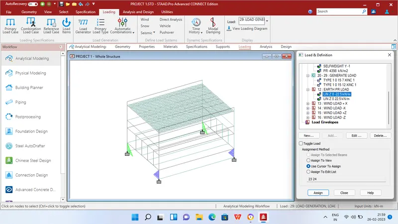
Step 7 - Then apply the following load cases
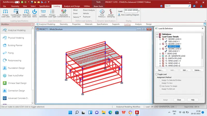
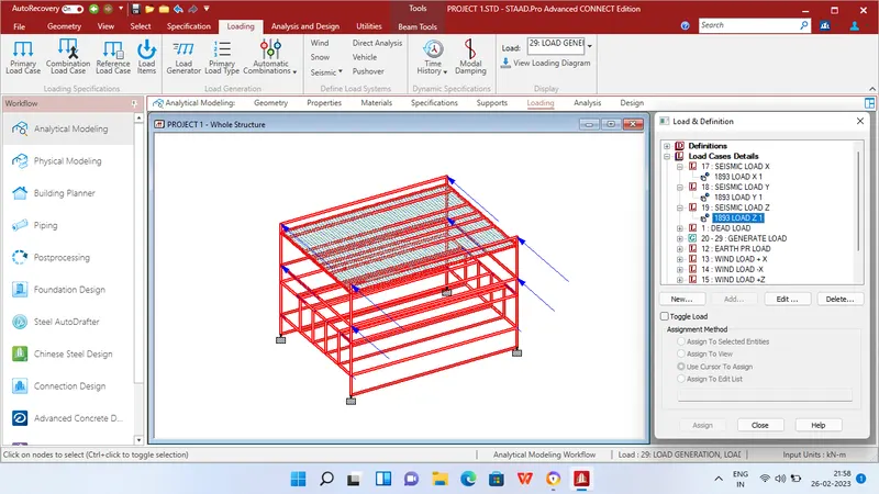
LOAD CASE 1 - Seismic load in X direction
LOAD CASE 2 - Seismic load in Y direction
LOAD CASE 3 - Seismic load in Z direction
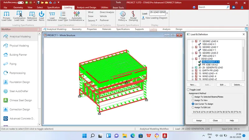
LOAD CASE 4 - Self weight for overall geometry 4893 KN as per calculated data
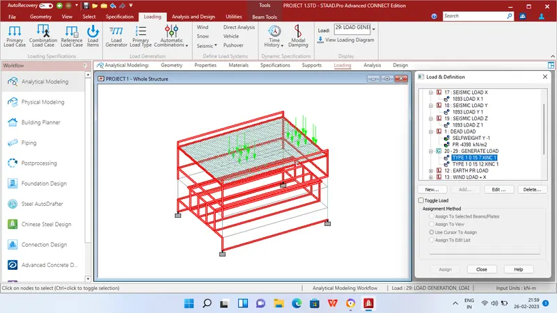
LOAD CASE 5 - Genaration load for IRS Live loading (METRO RAIL) 170 KN Per axle
LOAD CASE 6 - Earth pressure load 22.05 KN/m2 as per calculated data
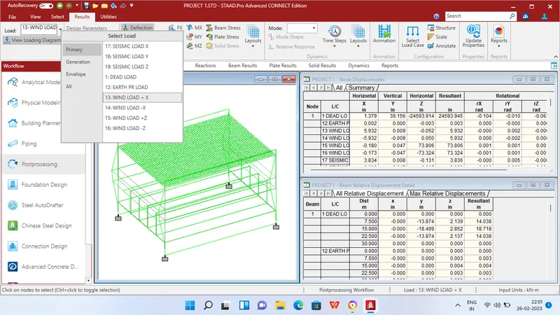
LOAD CASE 7 - Wind load +X direction
LOAD CASE 8 - Wind load -X direction
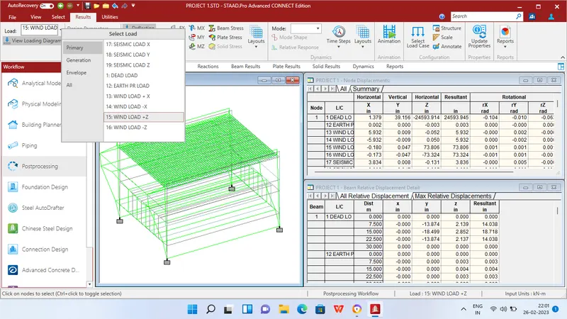
LOAD CASE 9 - Wind load +Z direction
LOAD CASE 10 - Wind load -Z direction
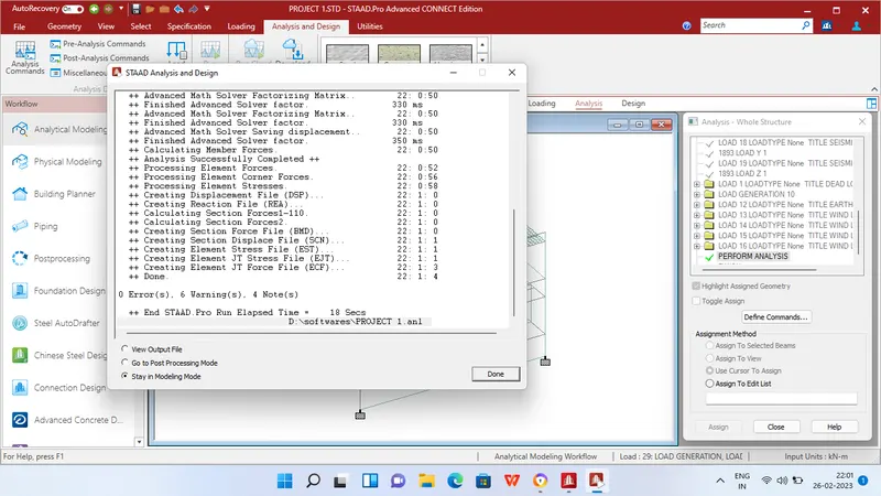
Step 8 - After applying the loads in analysis and design tab define commands for PERFORM ANALYSIS and click run analysis.
RESULTS
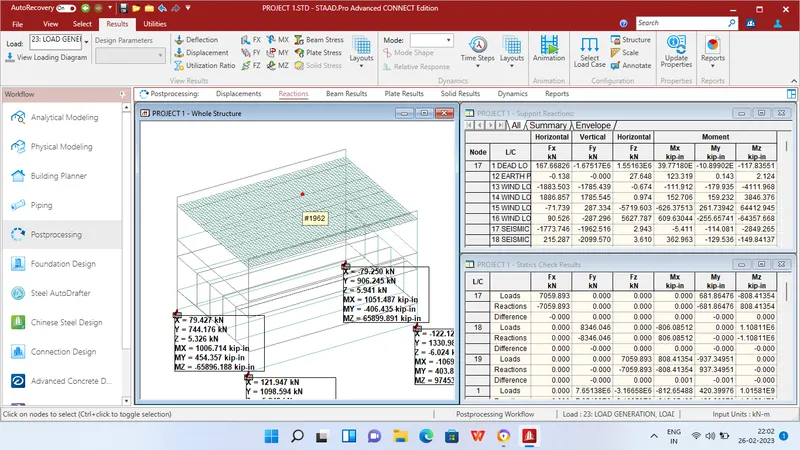
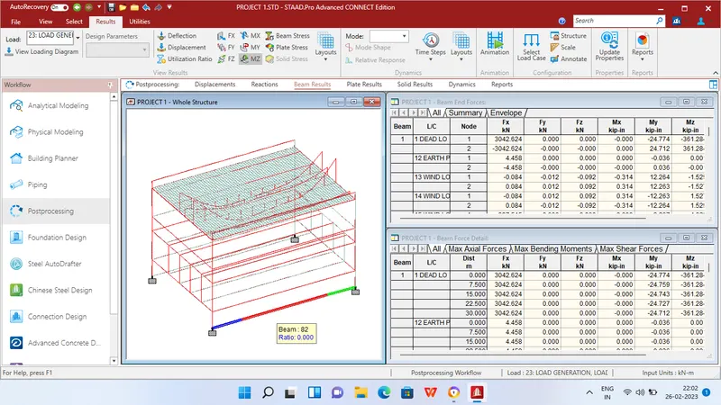
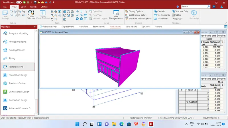
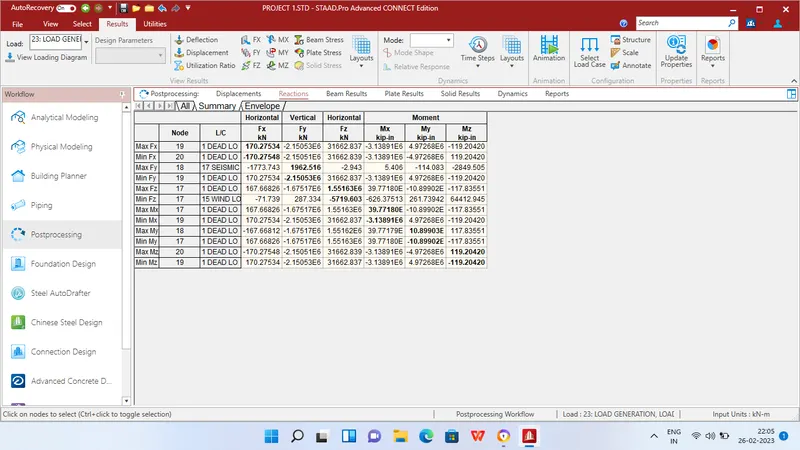
MAXIMUM BENDING MOMENT AT SUPPORT
Mx = 39.77180E KN/m at Node 17
My = 10.89903E KN/m at Node 18
Mz = 119.20420 KN/m at Node 20
MAXIMUM SHEAR FORCE AT SUPPORT
Fx = 170.27 KN/m at Node 19
Fy = 1962.51 KN/m at Node 18
Fz = 1.551 KN/m at Node 17
MAXIMUM BENDING MOMENT AT BEAMS
Mx = 69798.23 KN/m at Beam 2815
My = 11.65348E KN/m at Beam 23
Mz = 12.28915E KN/m at Beam 2956
MAXIMUM SHEAR FORCE AT SUPPORT
Fx = 1.31879E6 KN/m at Beam 80
Fy = 508.306 KN/m at Beam 2961
Fz = 598.71 KN/m at Beam 79
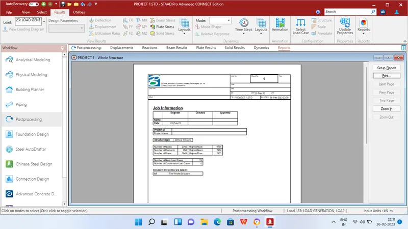
REPORT