Project 1
Q)
Analyze and design a steel building to 10T CRANE as per IS standard code in TEKLA STRUCTURAL DESIGNER. Refer the attached plan and elevation. Provide bracings and moment connection for lateral stability.
Consider dead, live, equipment and wind loading. Consider the brick wall loading for 150mm thick and 1.5 KN per sq m for wall and roof cladding.
Assume wind loading basic speed as 39m/s
Report of each member to be generated and extract drawings of structural plans from the software.
PROCEDURE:
1) open tekla, go to windows and select structure window.
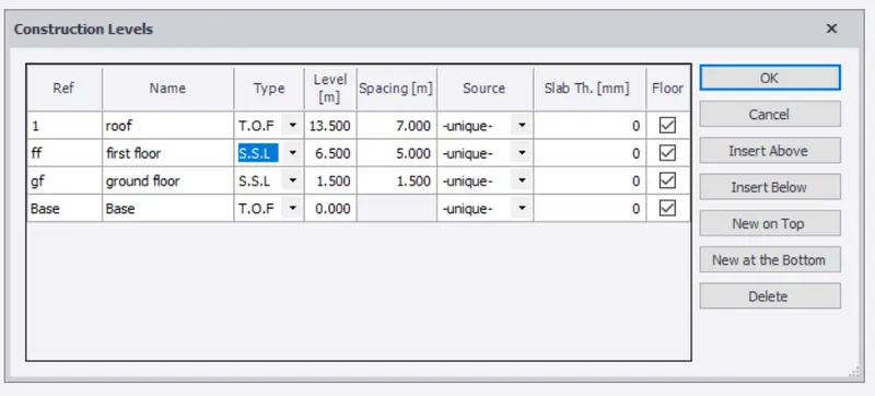
2) enter the levels as base ,ground floor, first floor and roof as per the question.
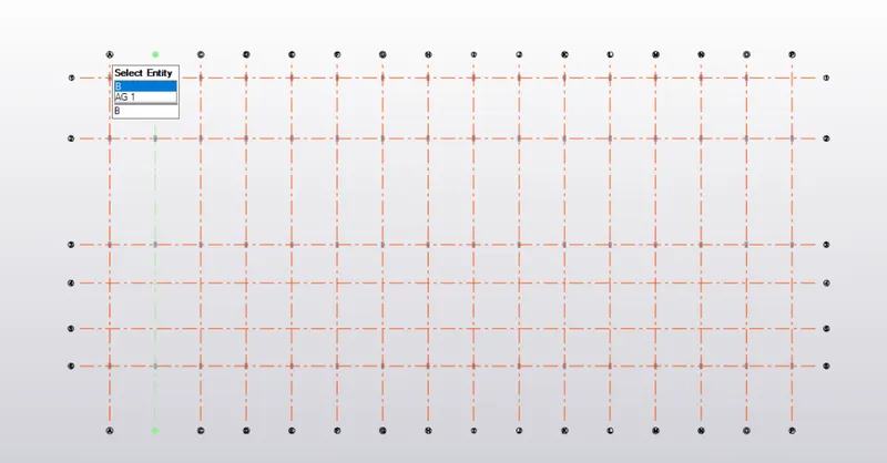
3) select grid lines and draw the grids according to ground floor plan.


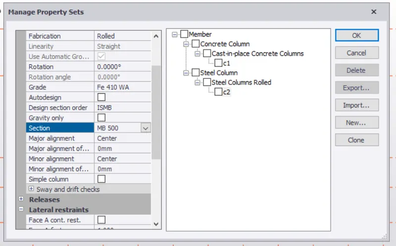
4) now go to manage property sets and define a new concrete column as 400*800 with grade of M45.
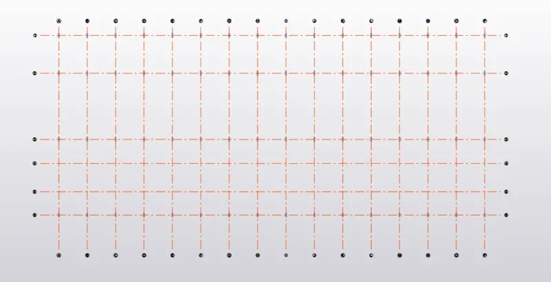
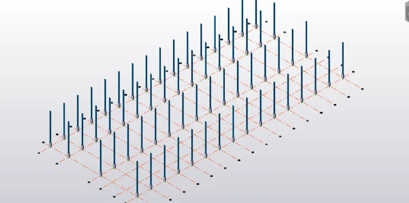
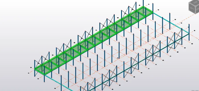
place the columns on the grid intersections.
now define a steel column of section ISMB 500, and place it at the grid intersections of first floor.
now define the primary beams as ISMB 500 and place it on the ground floor.
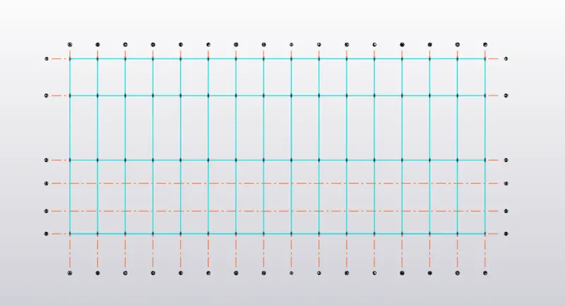
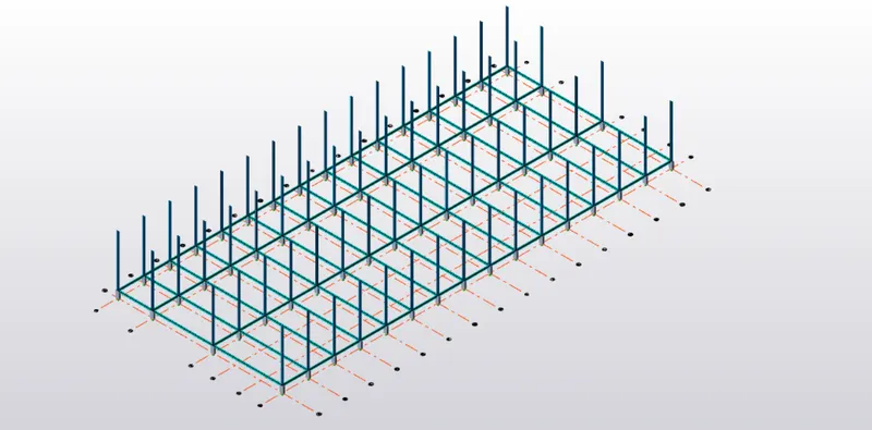
draw the same beams on the first floor and roof.
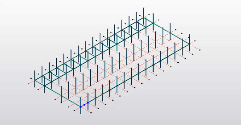
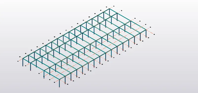
now define the frames for the model ,select any one frame and draw a central vertical line.
slope of the roof is 18degree, we need to find the height at which rafter is placed.
tan 18 = X/19
X = 6m
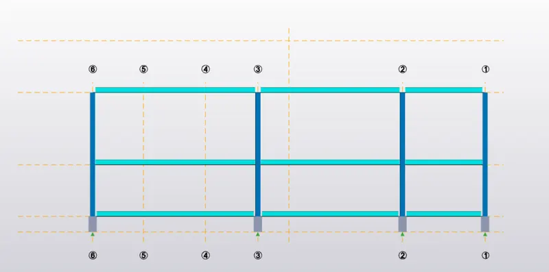
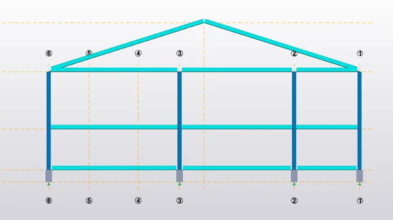
combination of beams columns rafter in the model.
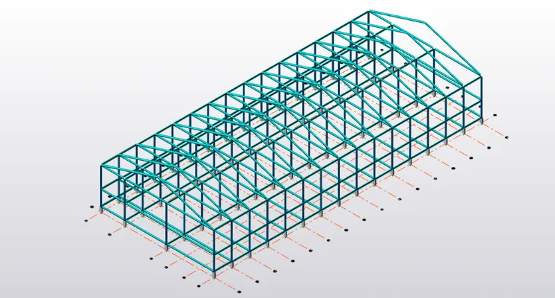
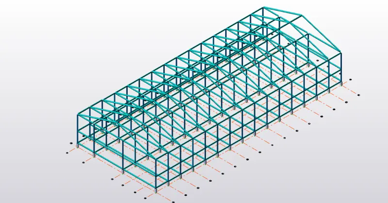
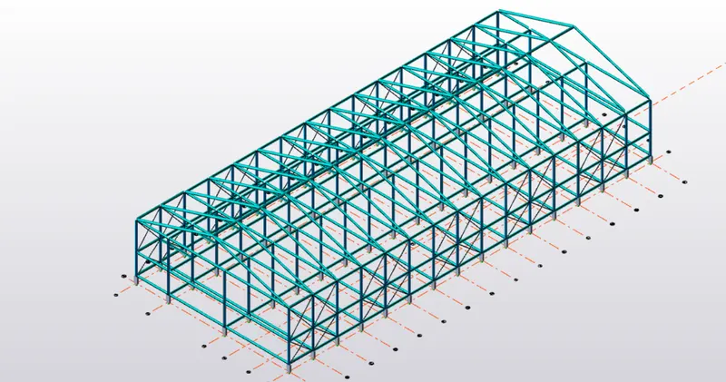
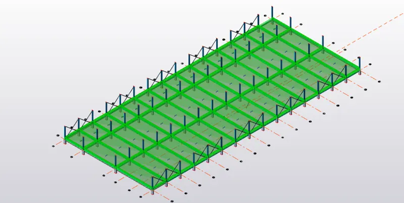
now go to slab sections and define a slab of thickness 300mm and grade M50.
as we can see there are three layers of slab, first layer is square shaped, so it will be two way slab.
other two rows are one way slabs.
repeat the same procedure for all three floors.
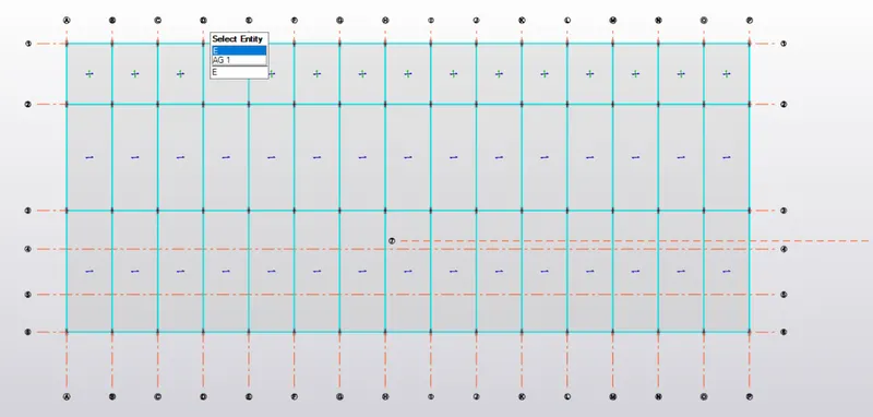
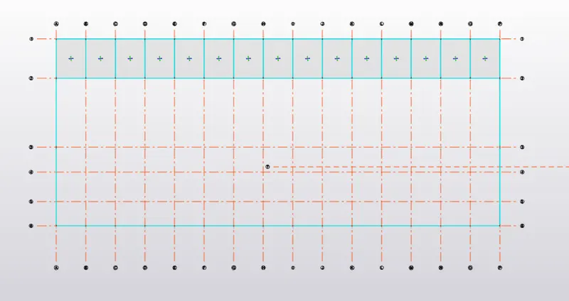
now assign the roof panels and wall panels.
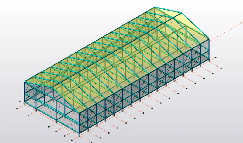
dead load calculation:
finish of 50 mm = 0.5*25 = 1.2Kn/m
brickwall load (ground floor ) = 0.15*20*5 = 15.5kn/m
brickwall load (first floor to roof) = 0.15*20*7 = 21.2kn/m
apply these loads to the entire model.
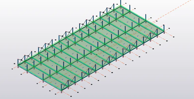
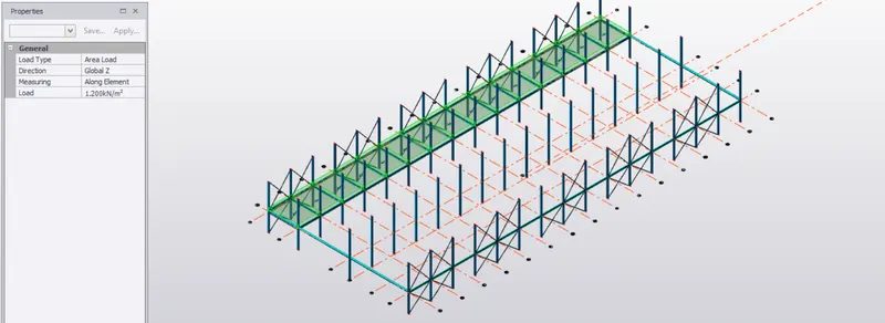
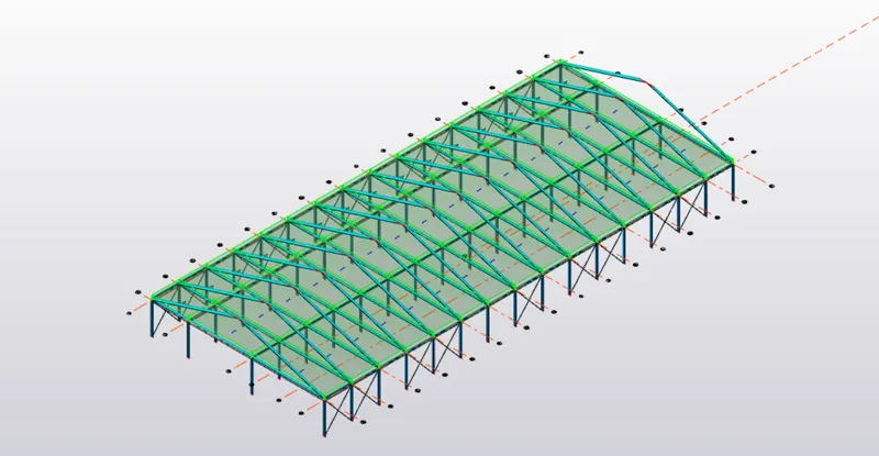
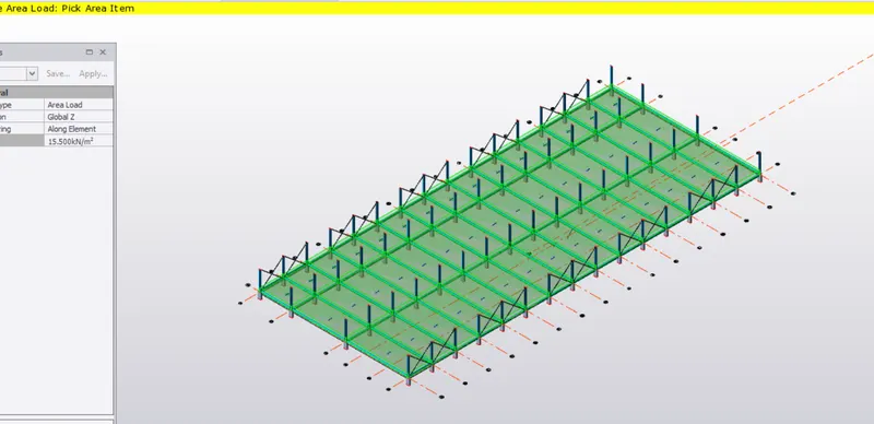
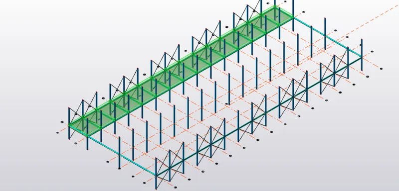
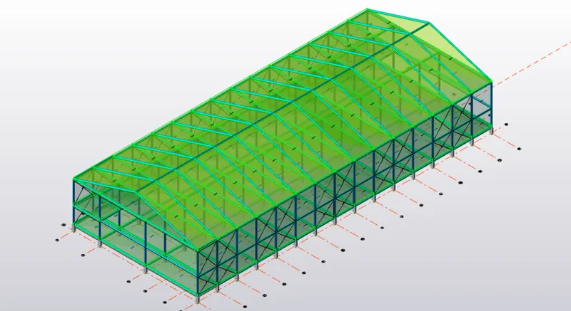
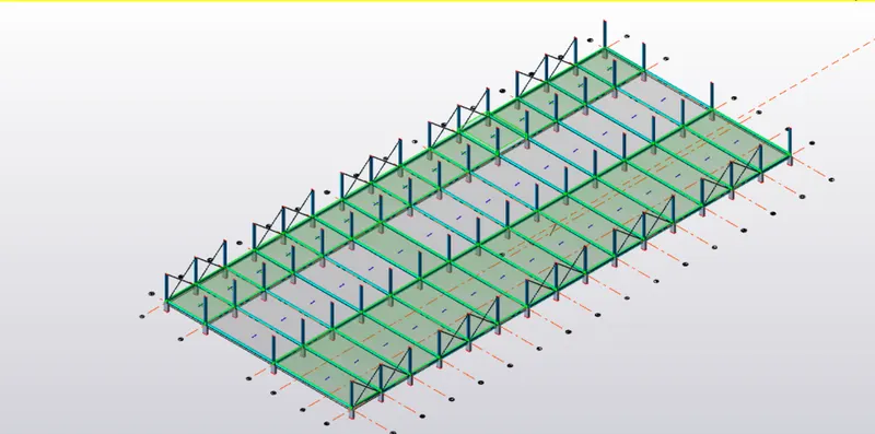
Live loads:
office room = 2.5kn/m
toilet = 2kn/m
meeting room = 2kn/m
pantry = 5kn/m
maintenance room = 2.5kn/m
staircase = 5kn/m
now apply these loads to each floor of the model.
WIND LOAD CALCULATIONS :
Vz = Vb*k1*k2*k3*k4
Vb = 39 m/s
k1 = 1 ( table 1 Is 875 - 3)
k2 = 1.03 ( table 2 Is 875 - 3)
k3 = 1
k4 = 1
Vz = 39*1*1.03*1*1
Vz = 40.17 m/s
Pz = 0.6Vz^2
Pz = 0.6*40.17*40.17
Pz = 968.17 N/m^2
Pz = 0.968 kn/m^2
along face A :
H = 18m H = 18m
L = 90m L = 90m
w = 38m w = 38m
Cp = 0.7 Cpe = 0.7
Cpe = 0.5 Cpi = -0.5
Cp = 0.2 Cp = 1.2
Pz = 0.968kn/m^2 Pz = 0.968 kn/m^2
load = 0.1936 kn/m load = 1.16 kn/m
along face B :
H = 18m H = 18m
L = 90m L = 90m
w = 38m w = 38m
Cp = -0.25 Cpe = -0.25
Cpe = 0.5 Cpi = -0.5
Cp = -0.75 Cp = 0.25
Pz = 0.968kn/m^2 Pz = 0.968 kn/m^2
load = -0.726 kn/m load = 0.242 kn/m
along face C :
H = 18m H = 18m
L = 90m L = 90m
w = 38m w = 38m
Cpe = -0.6 Cpe = -0.6
Cpi = 0.7 Cpi = -0.7
Cp = -1.3 Cp = 0.1
Pz = 0.968kn/m^2 Pz = 0.968 kn/m^2
load = -1.25 kn/m load = 0.0968 kn/m
along face D :
H = 18m H = 18m
L = 90m L = 90m
w = 38m w = 38m
Cpe = -0.6 Cpe = -0.6
Cpi = 0.1 Cpi = -0.1
Cp = -0.7 Cp = -0.5
Pz = 0.968kn/m^2 Pz = 0.968 kn/m^2
load = -0.6776 kn/m load = -0.484 kn/m
now apply these loads along each face of model.
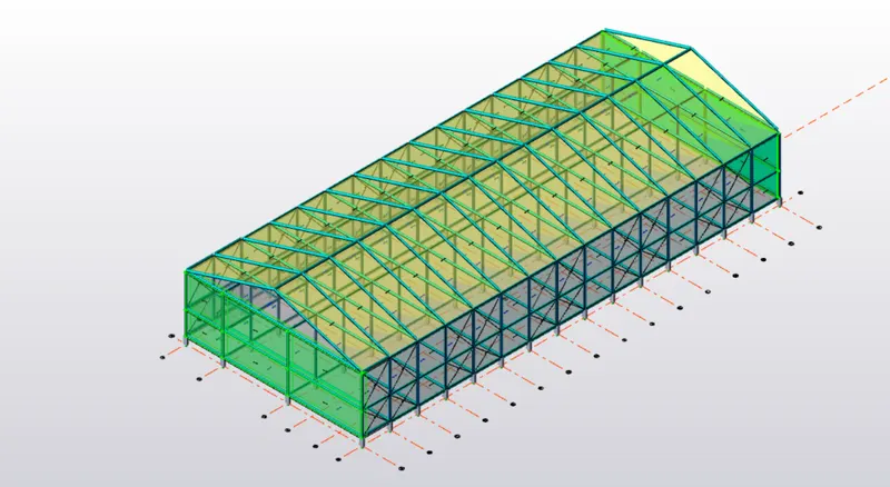
now apply the loads to roof considering one part as EF
H = 12m H = 12m slope = 18 degree
L = 90m L = 90m
w = 38m w = 38m
Cpe = -0.4 Cpe = -0.4
Cpi = 0.7 Cpi = -0.7
Cp = -1.1 Cp = 0.3
Pz = 0.968kn/m^2 Pz = 0.968 kn/m^2
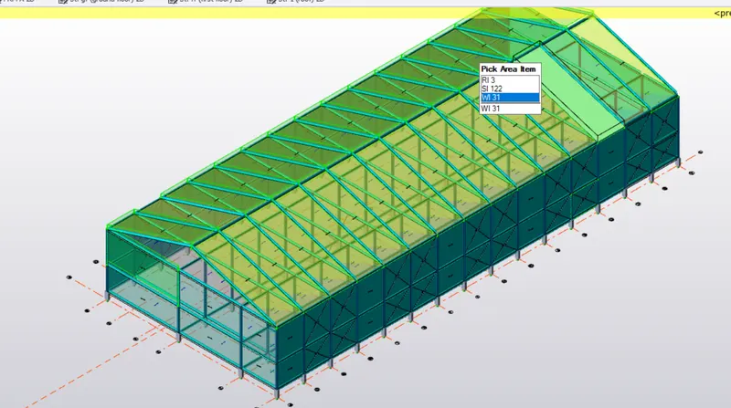
load = -1.06 kn/m load = 0.2904 kn/m

now apply these loads to the model.
crane load calculations :
crane capacity = 100kn
weight of crab = 35kn
weight of crane = 160kn
wheel base = 3m
distance between gantry rails = 20m
distance between gantry column = 6m
maximum wheel load = maximum point load + weight of crab = 135Kn
self weight of crane = 160kn/20 = 8kn
taking moment about B,
Ra*20 - 135*19 - 8*20*10 = 0
Ra = 208.25KN
taking moment about A,
Rb * 20 - 135*1 -8*20*10 = 0
Rb = 86.75Kn
maximum load on each wheel = Ra/2 = 104.125kn
maximum bending moment :
assume self weight of gantry girder = 1.5kn/m
total dead load = 1.8kn/m
moment at D,
Rc * 6 -104.125(2.25 + 3) - 104.125*2.25 = 0
Rc = 130.15 Kn
At C,
Rd*6 - 104.125(0.75+3) -104.125*0.75 = 0
Rd = 78.9Kn
Rc + Rd = 208.25Kn
bending moment under wheel load due to live load
= 78.9*2
= 156.18knm
bending moment due to impact = 0.10*156.18 = 15.618kn
total bending moment due to live load and impact load = 171.79knm
bending moment due to dead load = wL/2 = 8.1kn/m
maximum bending moment = 171.79 + 8.1 = 179.89knm
maximum shear force at D,
Rc * 16 - 104.125 *6 - 104.125 *3 = 0
Rc = 156.18kn ( maximum shear force due to wheel load )