Project 1
ROUTE THE WIRING HARNESS FOR ENGINEE
Aim : To route harness on given engine and prepare fatten view drawing in CATIA V5. Applocation of all packaging rules and industry best practices in design.
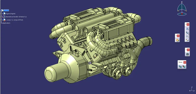
Given data
1.First step is to define all comonents as electrical :
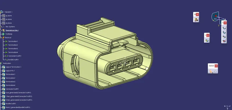
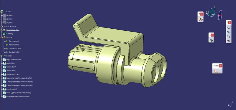
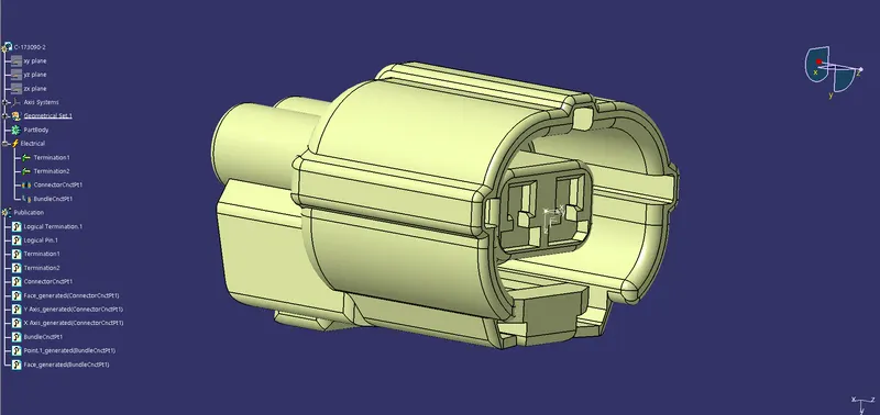
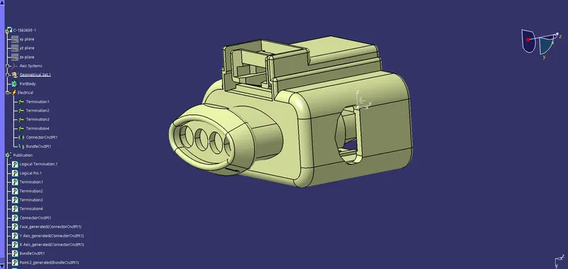
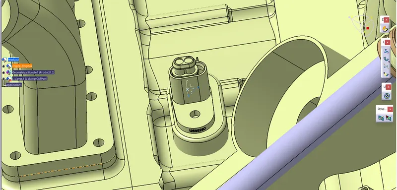
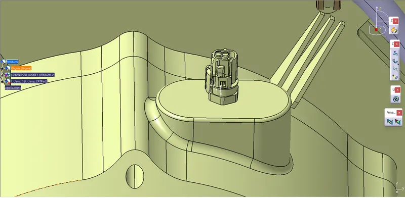
2.Second step is place all connectors in respective positions :
- Interconnecter is mounted on L clamp in left to right position, L clamp fixed on right side of the engine.
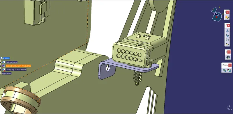
- Given engine is 16 cylinder engine so three way connectors fixed over the 16 juntions.
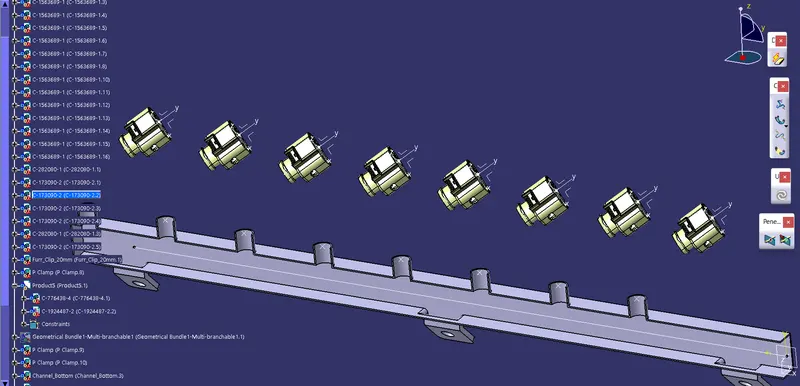
- All other connectors fixed over there respective places.
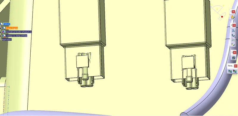
3.Third step is to route the wiring harness :
There are packaging rules, industry best practices which have to be followed when routing the wiring harness. Some of them mentioned below.
- Wiring harnes routing shall provide easy in manufacturing, accessibility,easy removal and easy maintanance of attached equipment and wiring routing.
- Routing through small stractural holes and openning shall be avoided, to minimize chaffing and handling of the wiring harness during installation.
- Avoid the harness and clipping in the blind zone of operator during harness or in assembly.
- Routing shall offer protection against possible damage through comman misuse such as being a hand fold and temporary support for test equipment.
- Provide additional slack to the harness according to sorroundings and harness bending requirements. If harness paassing through the closures/doors or tail gates the envolpe dimension during openning and closing of doors.shall be considered to provide the slack. Check the harness slack in open and close condition to avoid the excess slack.
- Provide additonal slack to harness branch which connects to the loads and covered with enclosures. This is to ensure that harness has enough length to allow the ease fittment and removal of lodaing during service.
- Harness routing started from interconnector and passes through three p clamp.
- In between three 6 branch points added to the bundle segment, from taht point to connetors bundle segnment have been created.
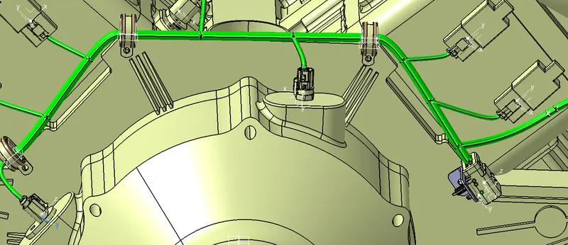
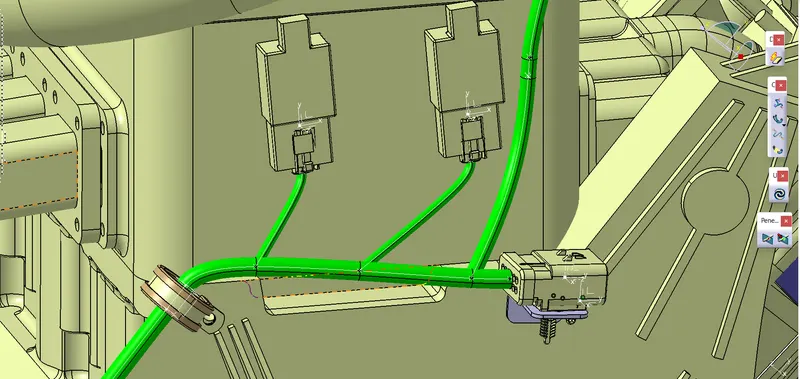
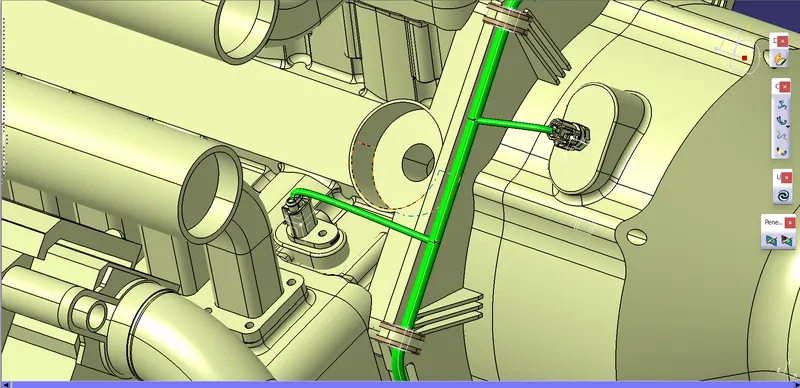
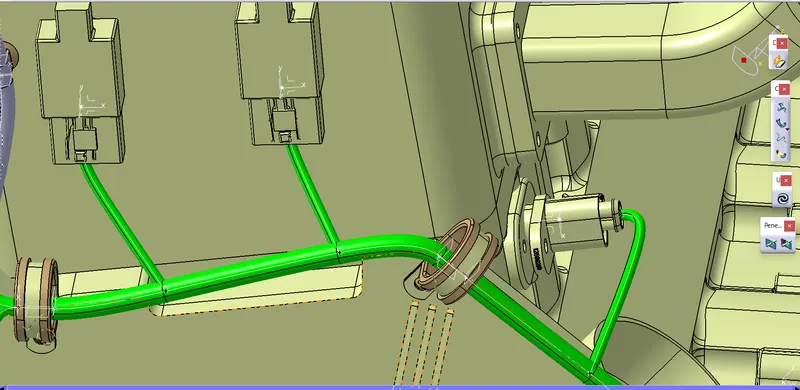
- From last P clamp, harness routed to cylinder connectors of left side through push clip.
- Guiding Channel have been used here to route the wiring harness in proper direction and it will also act like protection to the harness.
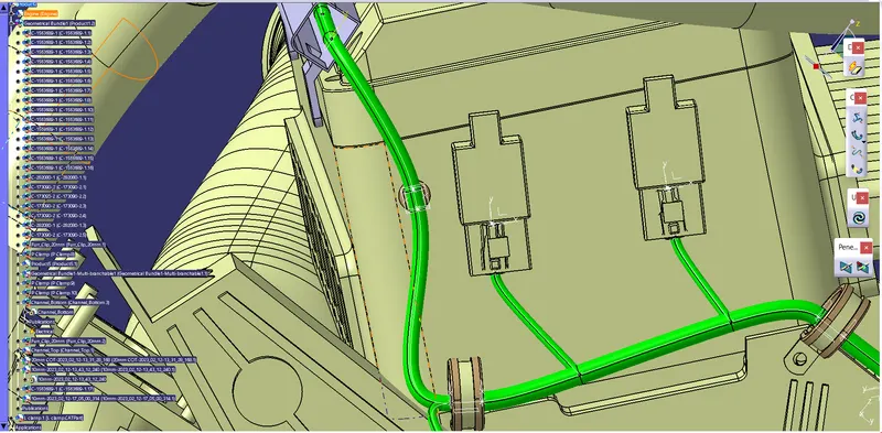
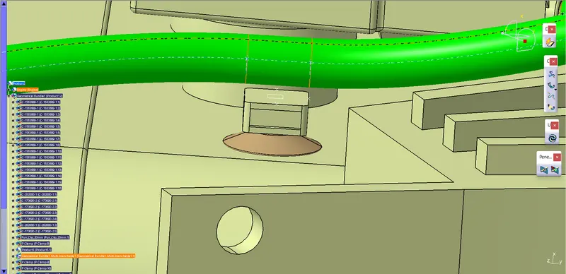
Push clip
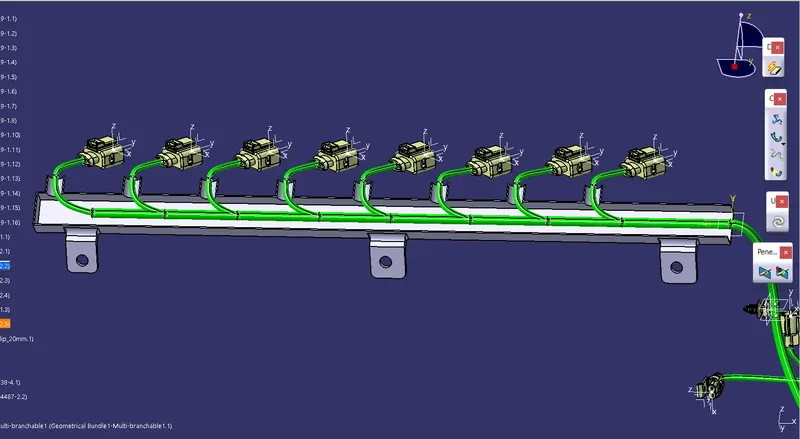
Harness routing through guiding channel
- Same process followed in another side of the engine.
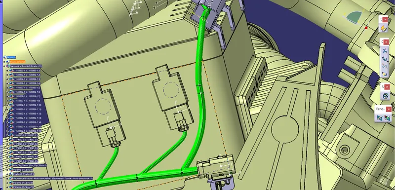
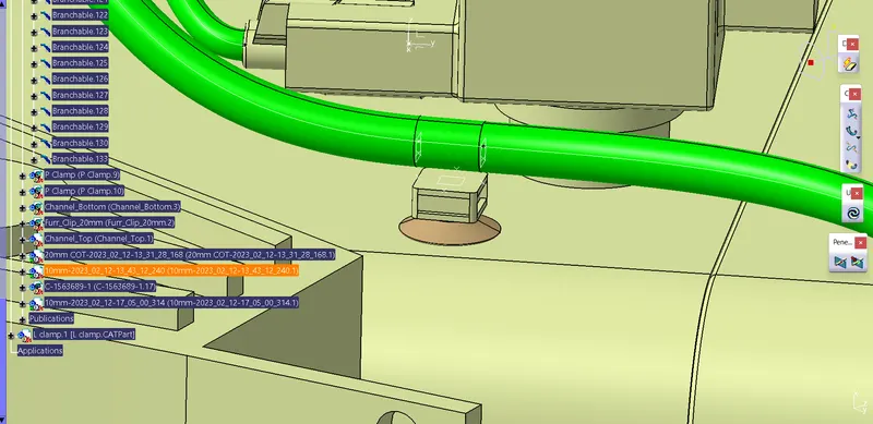
Push clip
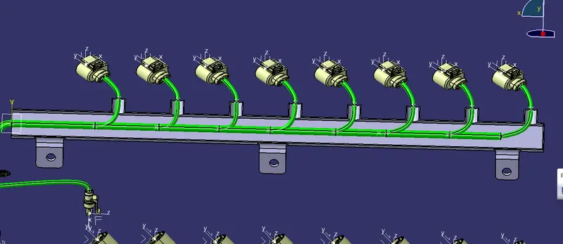
Guiding channel
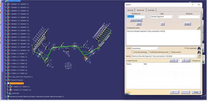
- After completing routing bundle segment continuity has been checked. Where it was fully connected.
4. Fourth Step is make Flattern Harness in Flattern workbench :
- In Flattern workbench first we have to set the flattering parameters.
- Next Harness has to be imported into the flattern workbench.
- Then flattern command used to flattern the harness.
- Commands like Rotate, Roll and Scaling is used to adjust the bundles.
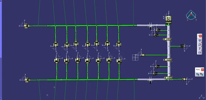
Flattern Harness
5. Drawing of Wiring harness :
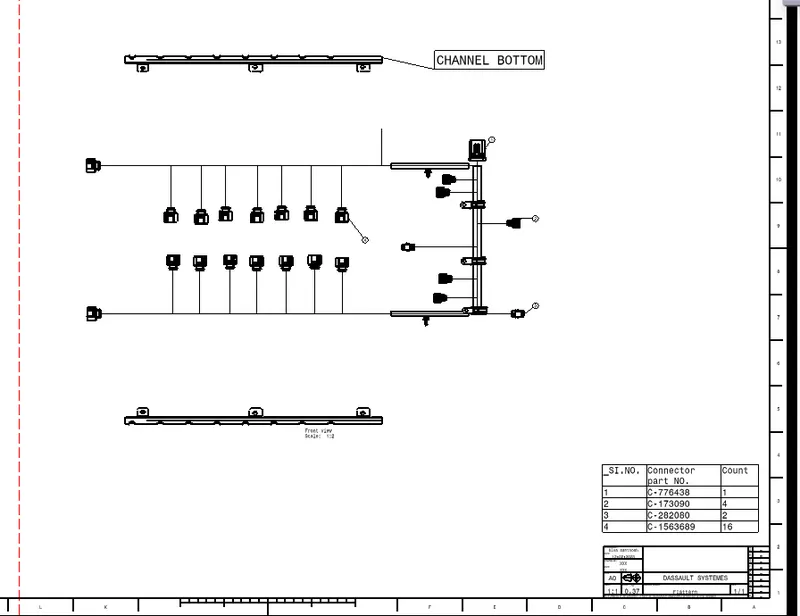
Drawing of wiring harness created in draiwing file.
Front view of Flattern Wirinh harness imported into the drawing Sheet. Connetors are mentioned as 1 2 3 & 4. Bill of materials has be ctreated.
CONCLUSION :
Route the wiring harness of engine has been completed by following all the packaging rules and industry best practices .Flattern wiring harness created and drawing of wiring harness also created.