Week 8 - Challenge 6 - Core & Cavity Design
CORE & CAVITY DESIGN FOR SWITCH BEZEL
To Create Core & Cavity design for Switch bezel it involes five important things draft analysis on plastic component, creation of parting surface, parting line, Core design & Cavity design.
1. Draft analysis made on plastic component. Draft analysis made along tooling direction in that it shows top side full green color(0 to 3 degree) and bottom side fully red (Above 3 degree). Face which was fully green considered as core side and face which was fully red considered as cavity side.
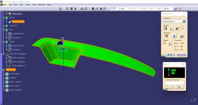 Draft Analysis on Switch bezel
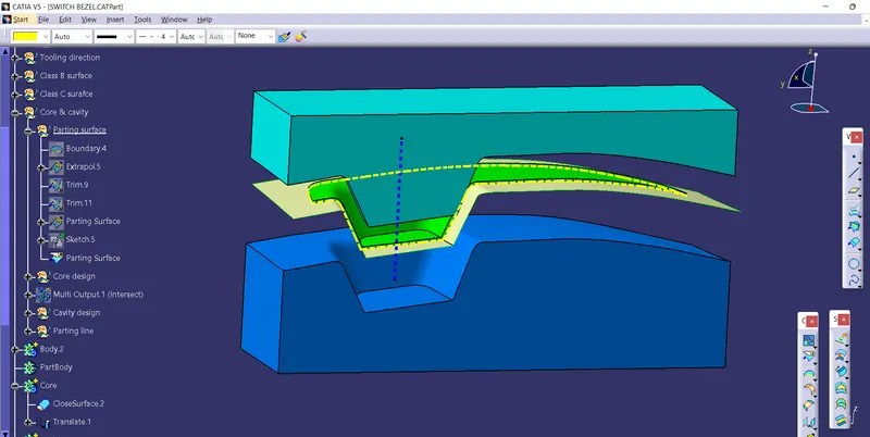
2. Parting surface is where core and cavity meets together and it is the biggest projection the outline of the part. Here I have created the parting surface with the use of clas b surface. first i extrapolated the class B surface and trimed it with class A & C surface. The surface with shape of switch bezel in internal is parting surface.
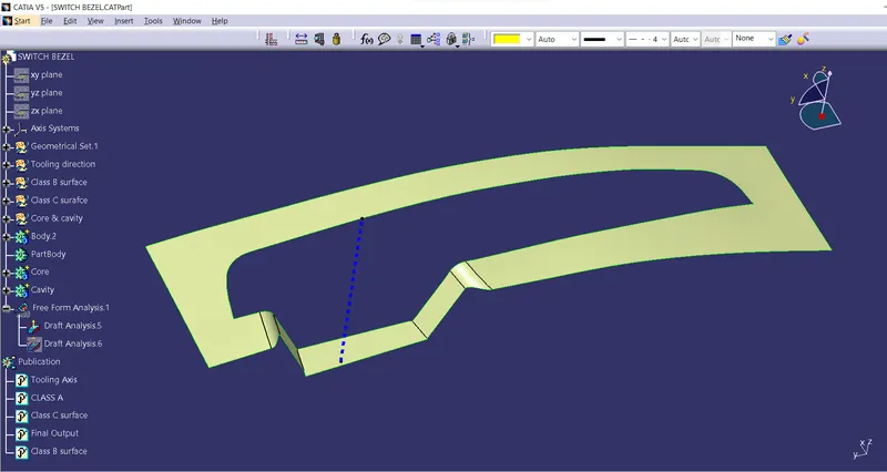 Parting surface
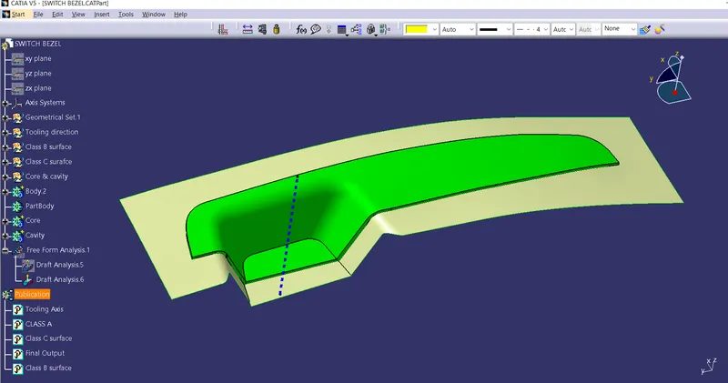 Parting surface with Switch bezel
3. Parting line is where of core,cavity,parting line and plastic component meets. Here I created the parting line By intersecting parting surface and switch bezel.the yellow dotted line is parting line.
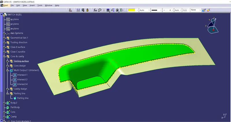 Parting line with component and Switch bezel
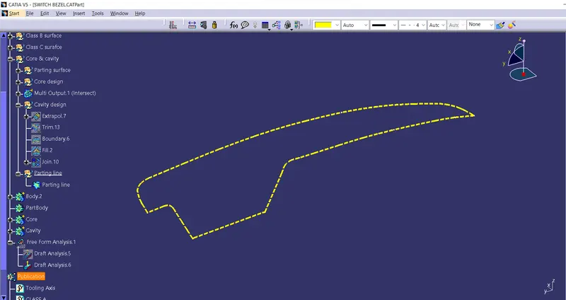 Parting line
4. Core side of the mold contains the projection of the switch bezel. Outer boundary of the parting surface Extruded and it was closed using fill at the end of the extrude. And converts to solid part in part workbench using closed surface.
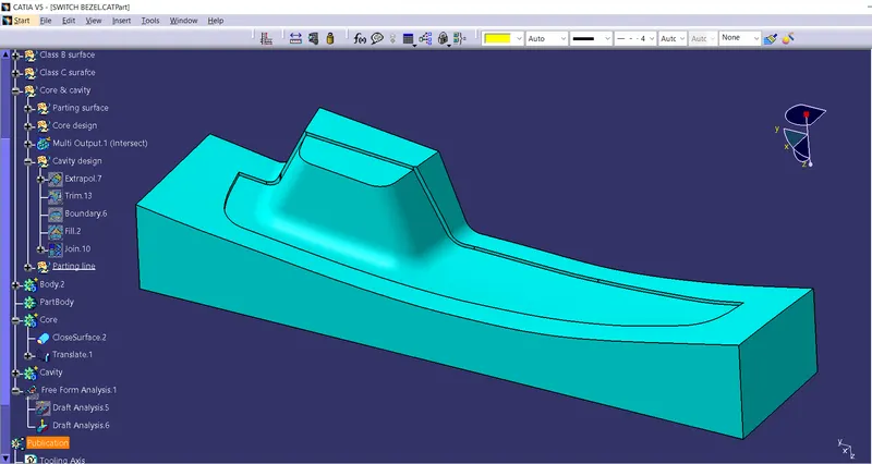 Core side
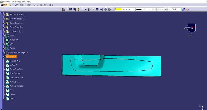
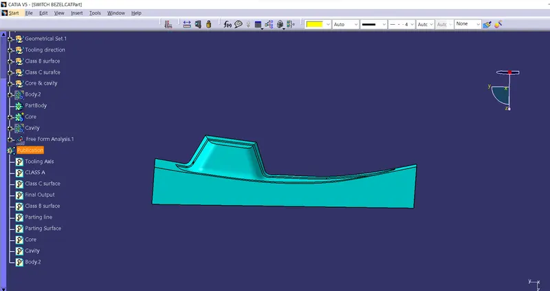
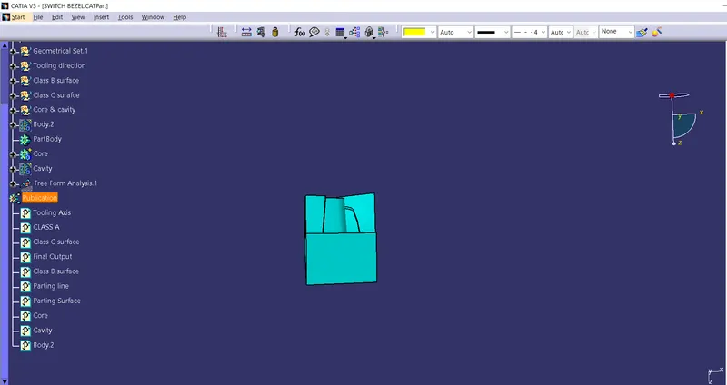
5. Cavity side of the mold contains the depression of the component. Like the same way how core side was created Cavity side also created. Outer boundary of the parting surface extracted and fill at the end. And converts to solid part using closed surafce.
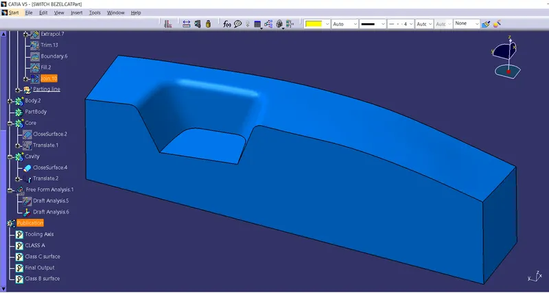 Cavity Side of mold
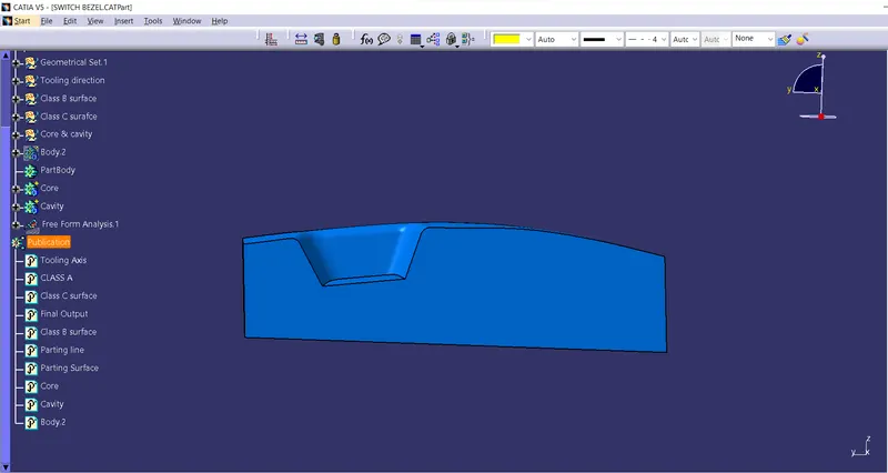
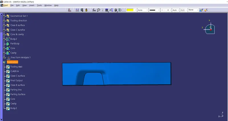
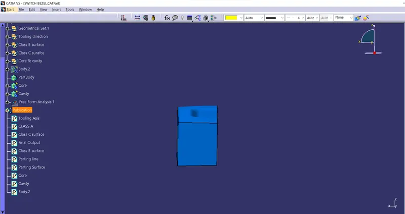
All Surface and parts are made along the direction of tooling axis. Below i have shown the intersection of Parting surface, core, cavity and switch bezel and all it together.
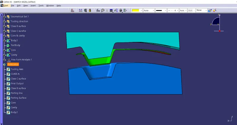
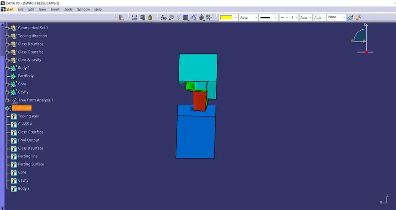
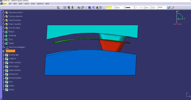
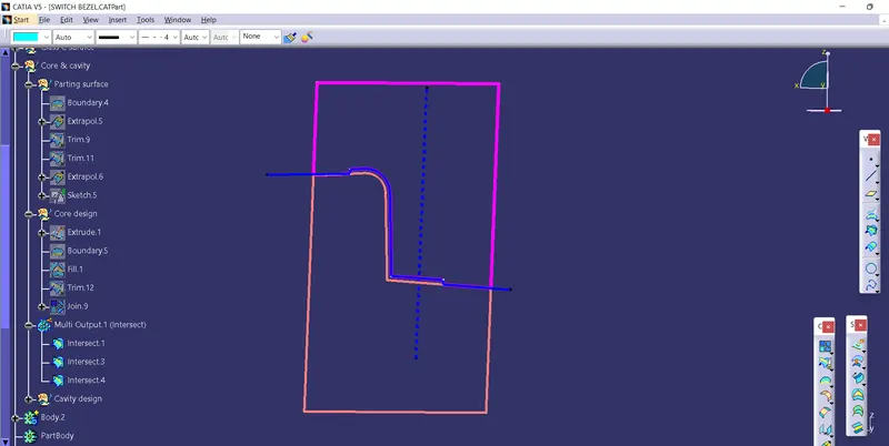 Intersection