Project 1
Routing the Wiring harness on the Given Engine
The engine
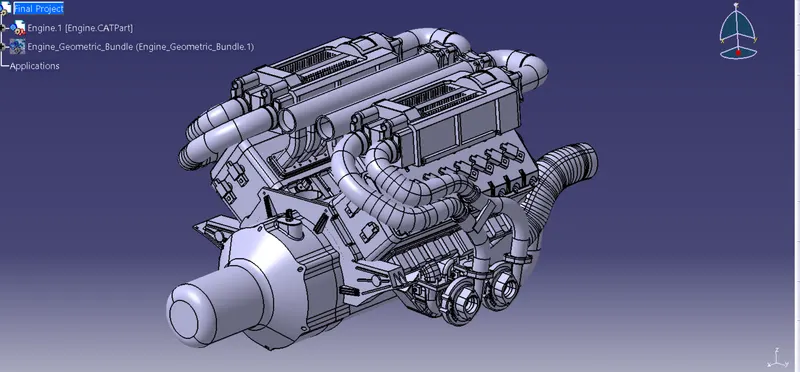
We have to insert a new product named engine harness geo. bundle and we have to define it as a geometrical bundle.
- import all the required connectors from the available website provided in that challenge and define all the connectors electrically and place the connectors in the required place where it has to be in the engine to route
- Interconnection connector
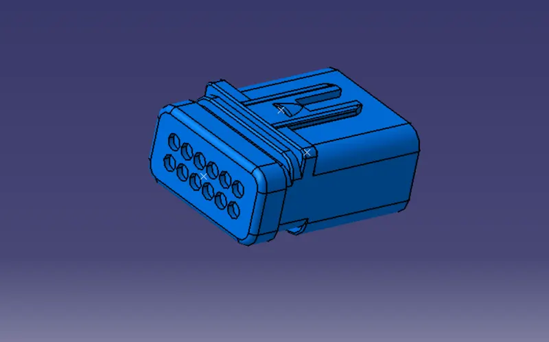
CONNECTOR 02
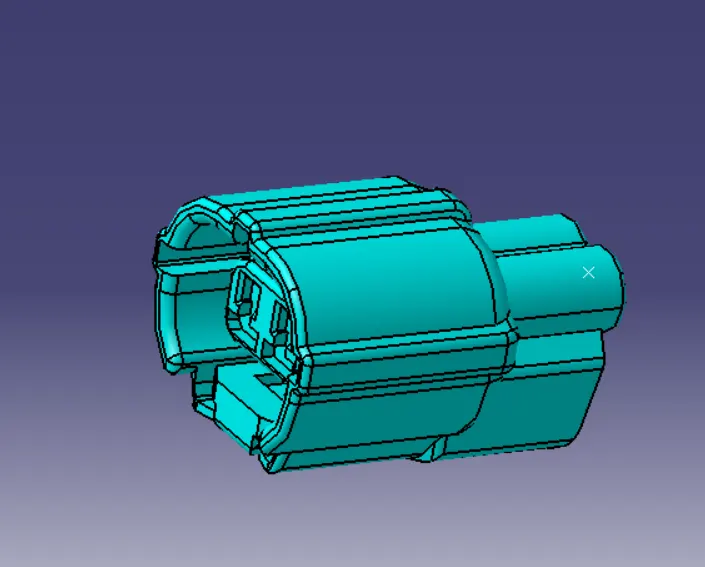
CONNECTOR 03
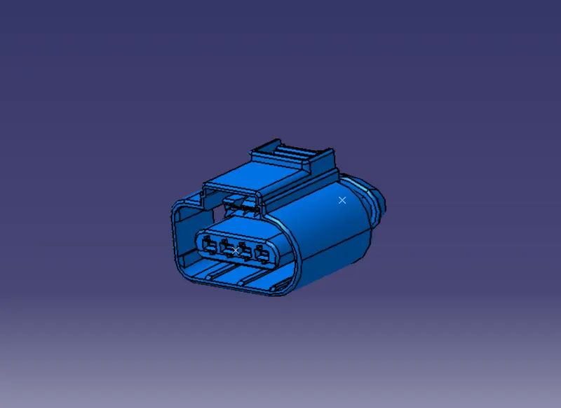
COOLANT TEMPERATURE SENSOR
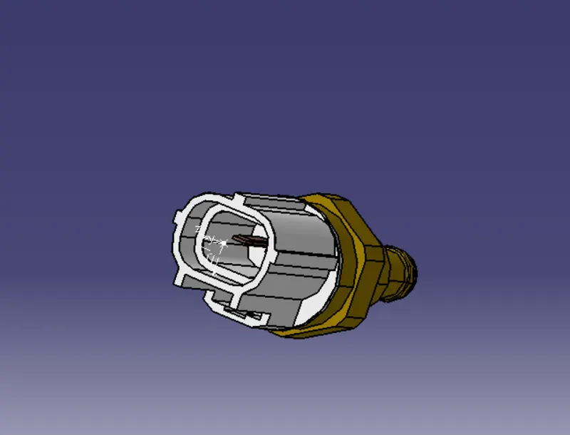
P CLAMP
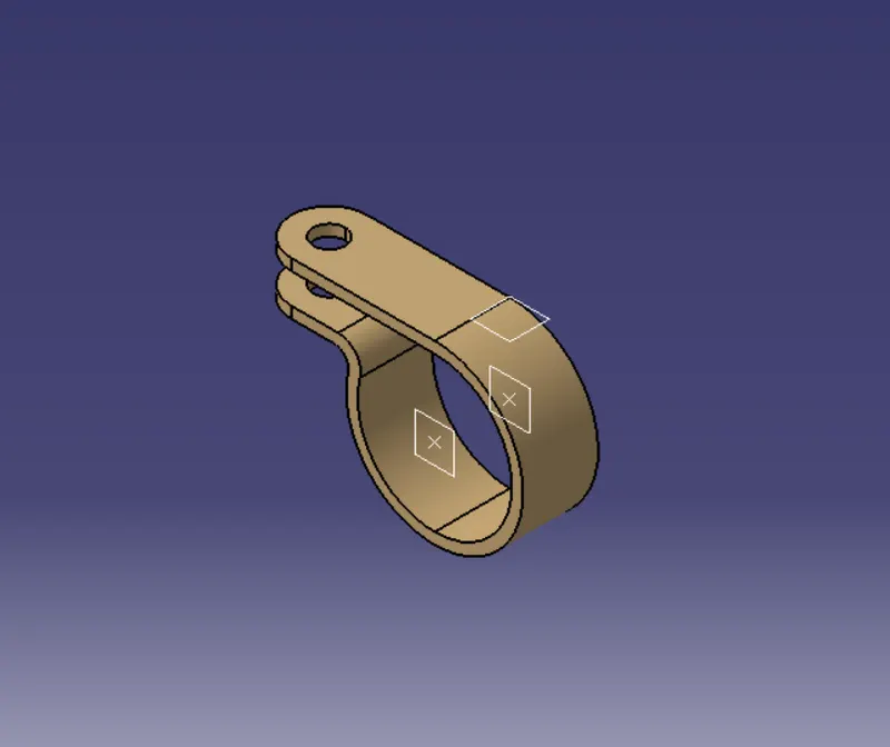
All the parts which is mentioned above are electrically defined.
CHANNEL BOTTOM
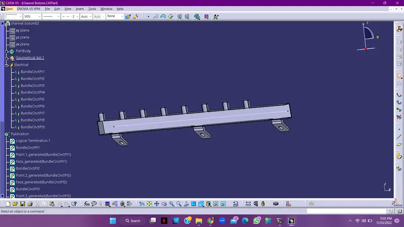
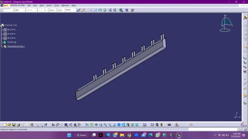
CHANNEL TOP
ALL THE CONNECTORS, P CLAMPS, AND CHANNEL TOP AND BOTTOM ARE PLACED AT THE EXACT LOCATION WHERE THEY SHOULD BE PLACED ON THE ENGINE.
After that we have to start the routing from the main connector called the interconnection connector which goes through the p clamps and channel bottom, we have to route the channel bottom by using the external line which is placed in the gap as shown below;
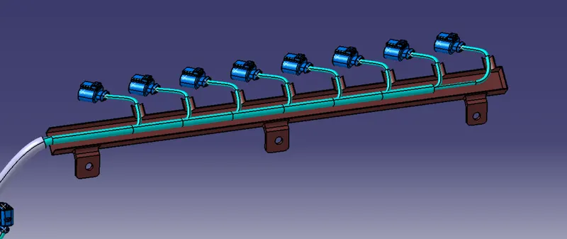
the engine will look like this after the routing is completed:-
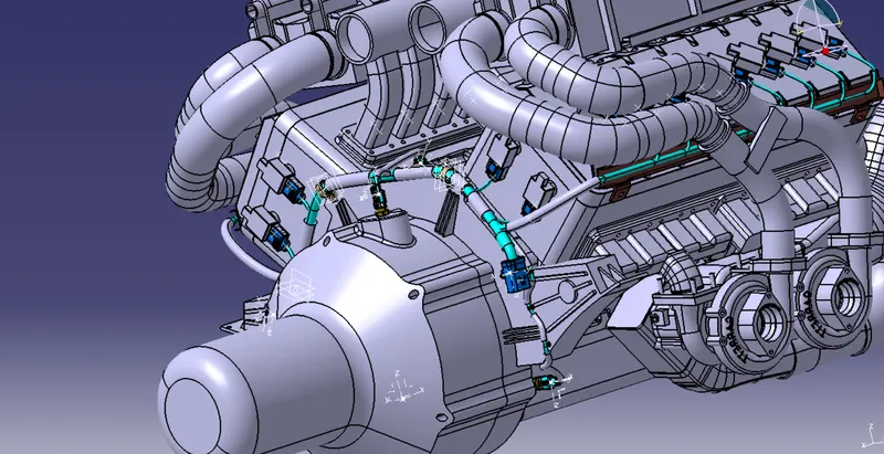
FLATTENING THE GEOMETRICAL BUNDLE.
Step 1
Open a new part and it as required, and open the flatten workbench and define the flattening parameters and mentioned in the vedios and then extract the geometrical bundle from the main engine contrast, and then try to flatten it by using the flattening command and select the flat face and then select the maioin bundle which is coming out the interconnection connector and also check is every bundle is connected properly.
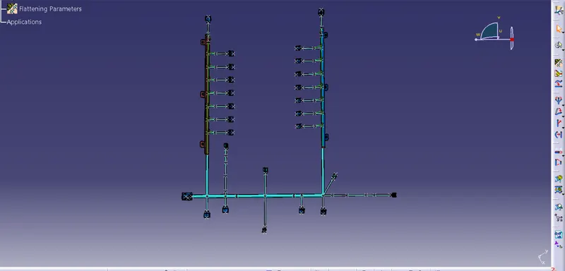
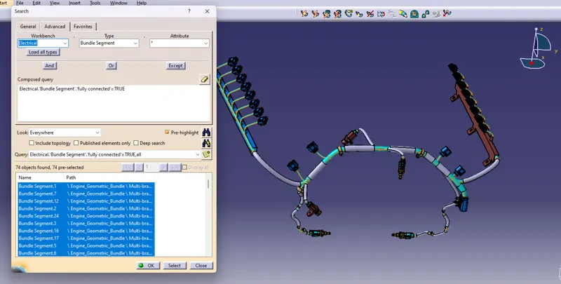
before doing this we have to ensure that all the bundle are fully connected or not:-
DRAFTING THE GEOMETRICAL BUNDLE
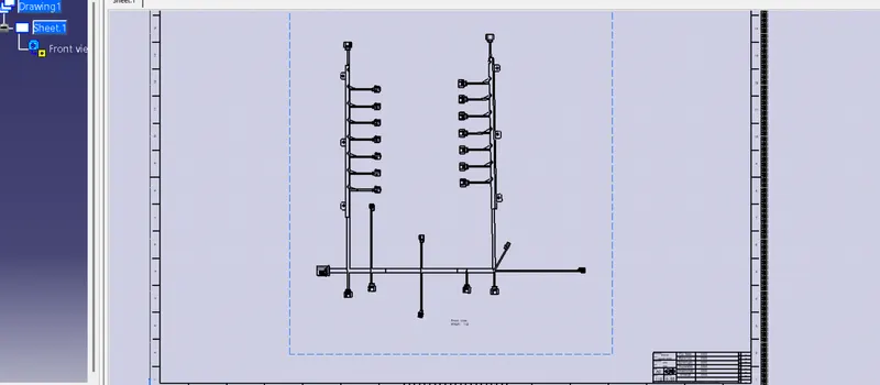
And then, open a new drawing sheet and insert the front view of the geometrical bundle and also try to name all the parts in a table as shown below;-