Project 1
PROJECT 1:
QUESTION 1:
1a)DESIGN THE BATTERY PACK CONFIGURATION :
PARAMETERS:
- Battery pack power = 150kW
- Battery pack voltage = 120V
- Nominal cell voltage = 3.6V
- Cell capacity = 3500mAh
EQUATION:
- No.of cells in series = Battery pack voltage/nominal cell voltage
- No.of cells in parallel = Continuous current/Nominal battery capacity
CALCULATIONS:
- The number of cells in series can be calculated as
No.of cells in series = Battery pack voltage/nominal cell voltage
No.of cells in series = 120/3.6
No.of cells in series = 33.33
- Case 1:considering 33 cells
The nominal battery pack voltage = 33*3.6
The nominal battery pack voltage =118.8V
The max battery pack voltage = 33*4.2 = 138.6V
- Battery max voltage >Battery nominal voltage ,condition satisfies
- So this can be considered
- Case 2:Considering 34 cells
The nominal battery pack voltage = 34*3.6
The nominal battery pack voltage =122.2V
The max battery pack voltage = 34*4.2 = 142.8V
- Battery max voltage V
- Considering the motor max voltage will be higher
- Choosing 34 cells to boost the voltage and better performance
- The battery pack model will have 34 S configuration
- Now we have to find No.of cells in parallel
No.of cells in parallel = Continuous current /cell nominal capacity
- The continuous current can be calculated as
Current = power/voltage
Current =150000/120
Current = 1250Ah
- The no.of cells in parallel
No.of cells in parallel = Continuous current /cell nominal capacity
No.of cells in parallel = 1250/3.5
No.of cells in parallel = 357.17
- Case 1:357 cells in parallel
The batttery pack capacity = 357*3.5 = 1249.5Ah
- Case 2:358 cells in parallel
The battery pack capacity = 358*3.5 = 1253Ah
- Choosing case 2 of 358 cells for better performance
- The no of cells in parallel is 358
RESULT:
- The battery pack configuration will be 34 S 358 P to achieve 150kw and 120V application
1b)BMS TOPOLOGY FOR BATTERY PACK
- The BMS topology for 34S358P will be Master slave BMS topology
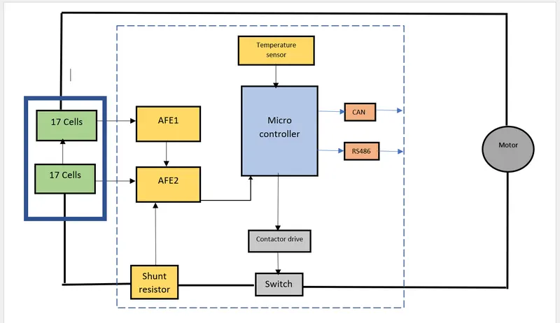
- The 34 series cells arranged 2 module of 17 series battery
- Because the AFE can only read maximum of 18 cells at a time
- The 17 series cells voltage individually read by AFE (analog front end)
- The AFE converts analog voltage signal to digital signal
- The AFE 1 carries voltage signals of first 17 cells and given to AFE 2
- AFE 2 carries signals of next 15 cells along with signals from AFE 1 connected to the microcontroller
- The microcontroller act as Master and AFE 1,2 act as slaves
- Microcontroller also get the signals from temperature sensor and current sensor
- According the sensor output ,microcontroller controls the circuit by switching ON & OFF through a contactor drive
- Shunt resistor used to measure the charge/discharge current
- Temperature sensor used to measure temperature of battery
- The switch used will be MOSFET or contactor/relay
QUESTION 2:
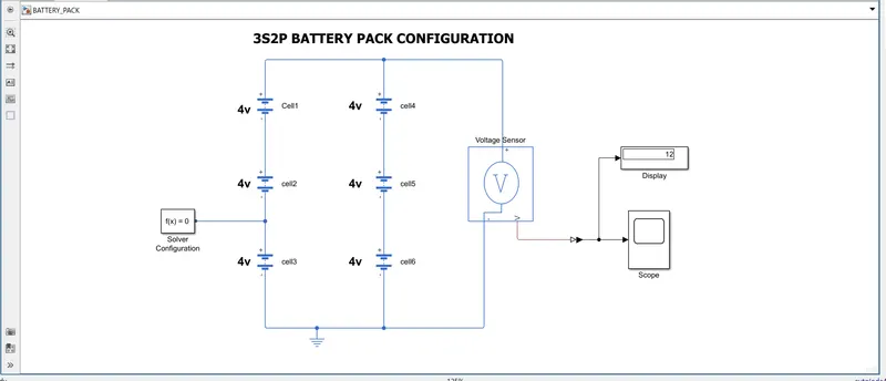
BUILD A 3S2P BATTERY PACK CONFIGURATION USING SIMULINK:
SIMULINK MODEL:
REPORT:
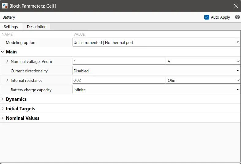
- The battery from simscape used to build thi model
- The cell parameters choosen as follows
- For 3S2P configuraton ,6 cells used in the model
- 3 cells connected in series and connected in parallel with other 3 cells connected in series
- The output voltage measured through voltage
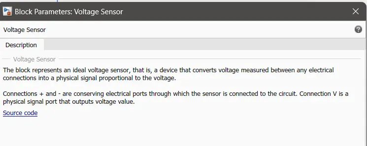
- And connected to scope and display block
- The circuit is grounded using a electrical reference
RESULT:
- For 3 cell of 4V connected in series ,the output voltage of battery pack will be 12 V
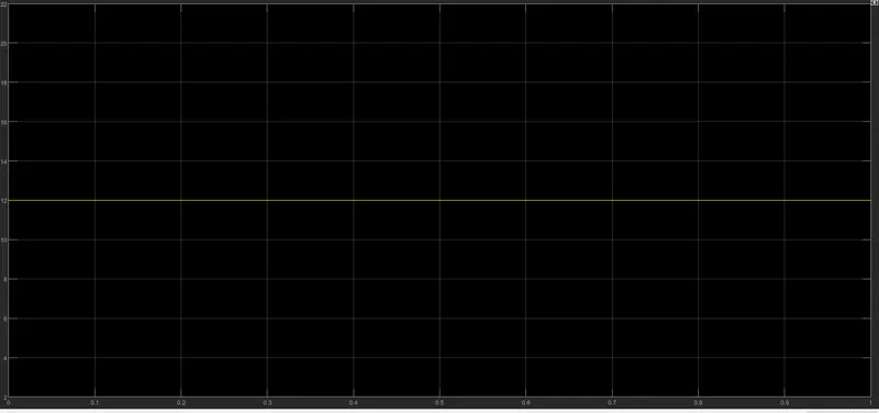
- We are getting 12V constant output
CONCLUSION:
- Designed 3S2P battery pack configuration in simulink and outputs verified