Project 1
Design a Multi-Parameter Patient Monitoring System to acquire physiological signals and display them on a color LED screen. The system should have capability to work on mains and battery. The following are the design parameters:
Design a multi-parameter physiological monitoring system and what physiological signals do you propose to choose. Give the details of the parameters, specifications, sensors or transducers proposed to be used
A multiparameter monitor is a medical device for monitoring a patient’s vital signs. It is mainly used in intensive care, hospitalization or ER. In general, basic models are used to monitor cardiac activity (ECG), blood pressure (NIBP), respiration, oxygen saturation (SpO2) and temperature.
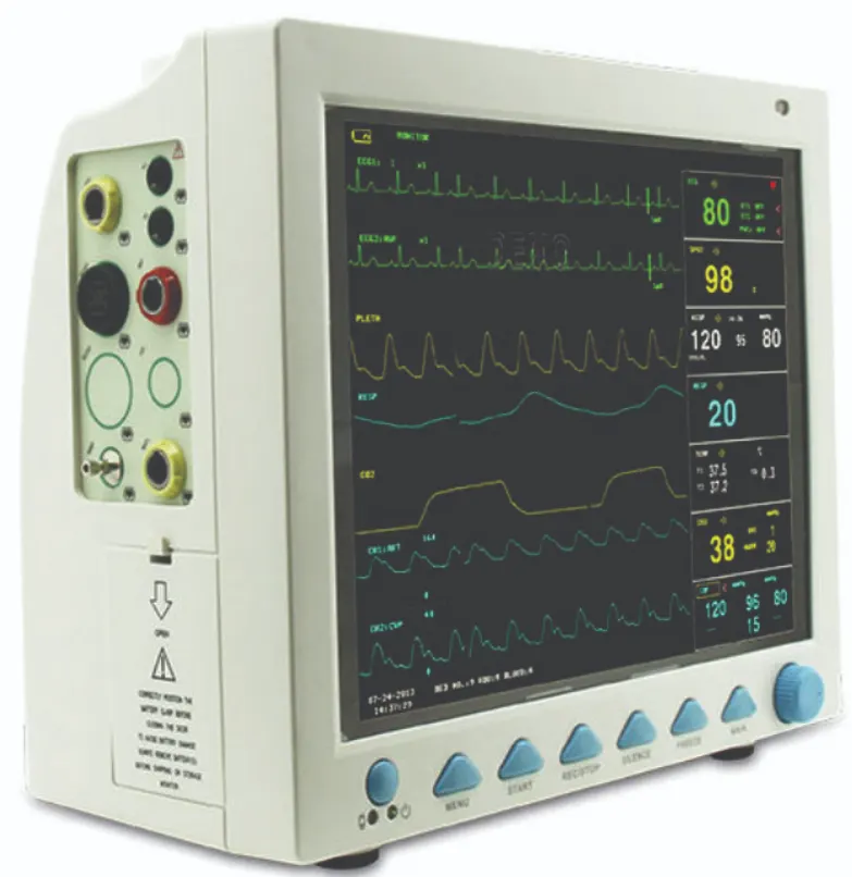
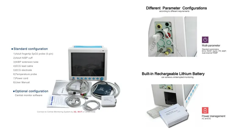
Design of Multi-Parameter Patient Monitoring System:
- Physiological signals:
- Heart rate (HR): This can be measured using an electrocardiogram (ECG) sensor, which detects the electrical activity of the heart and converts it into a trace on a monitor. The HR can also be measured using a pulse oximeter, which measures the oxygen saturation of the blood.
- Blood pressure (BP)/blood pressure (NIBP): This can be measured using a sphygmomanometer, which consists of an inflatable cuff placed around the upper arm and a pressure gauge. The cuff is inflated to occlude the flow of blood in the artery, and then gradually deflated while measuring the pressure at which the pulse can be heard using a stethoscope.
- Respiratory rate (RR): This can be measured using a respiratory inductive plethysmograph (RIP) sensor, which is a belt placed around the chest that detects changes in chest wall movement during respiration. The RR can also be measured using a thermistor, which is a temperature-sensitive resistor placed in the exhaled breath that changes resistance with changes in temperature due to respiration.
- Temperature: This can be measured using a thermometer, which can be placed in the mouth, ear, or under the armpit.
- ECG
- SpO2 oxygen saturation
- skin conductance level (SCL)
- blood volume pulse (BVP)
Multiparameter physiological monitor specifications
- Real-time remote monitoring of patients
- It can transmit and receive the data remotely
- Vital parameters can be monitored from the hospital through home monitoring
- The patient data monitored in the ambulance can be transferred to the emergency room in the telemedicine center in the hospital. It helps the doctors to be ready with the treatment protocols according to the vital signs
- All the data acquired can be sent to the cloud for an expert or second opinion of the experts
- In the intensive care unit, 8 to 9 monitoring systems are connected to the central nursing where all the vital information can be monitored by the doctor or healthcare provider.
Details of the parameters, specifications, sensors or transducers proposed to be used
- Mains power supply: The device can be powered using a mains power supply, such as a wall outlet or a generator.
- Battery: The device can also be powered using a rechargeable battery, which can be charged using the mains power supply when available.
- ECG sensor: This sensor detects the electrical activity of the heart and sends the signal to the ECG amplifier.
- Pulse oximeter: This sensor measures the oxygen saturation of the blood and sends the signal to the pulse oximeter amplifier.
- Sphygmomanometer: This consists of an inflatable cuff and a pressure gauge, which measure the BP and send the signal to the BP amplifier.
- RIP sensor: This sensor detects changes in chest wall movement during respiration and sends the signal to the RR amplifier.
- Thermistor: This sensor measures changes in temperature due to respiration and sends the signal to the temperature amplifier.
- Amplifiers: These amplify the signals from the sensors and send them to the microcontroller.
- Microcontroller: This processes the signals from the amplifiers and displays the data on the LED screen. It also has a memory for storing the data and a connection for transferring the data to a computer or external storage device.
- LED screen: This displays the data from the microcontroller in a user-friendly format.
- Alarm system: This generates alarms when certain physiological parameters fall outside of a predetermined range.
Specifications of non invasive blood pressure
Technique: Oscillometric
Measurement mode: Manual , Automatic and STAT
Measuring time: <30 seconds (typical adult cuff)
Measuring range: Systolic pressure: 40mmHg~275mmHg, Diastolic pressure: 10mmHg~210mmHg, Mean arterial pressure: 20mmHg~230mmHg
Specifications of SpO2
Transducer: Dual-wave length LED
SpO2 measuring range: 0%~100%
SpO2 measuring accuracy: 2% for range from 70% to 100%
Pulse Rate measuring range: 0 to 250 bpm. Accuracy +/-2%
Specifications of ECG
Heart Rate measuring range: 15bpm~350bpm
Heart Rate measuring accuracy: ±1% or ±2bpm
Specifications of Temperature range
Measuring range : 21.0°C~50.0°C
Measuring accuracy: ±0.2°C for range from 25.0°C~45.0°C
Specifications of Respiration Rate
Respiration Rate measuring range: 0rpm~120rpm
Respiration Rate measuring accuracy: ±5% or ±2rpm
2. Draw the detailed block schematic of the multi-parameter monitoring system with all the features required as a monitoring system
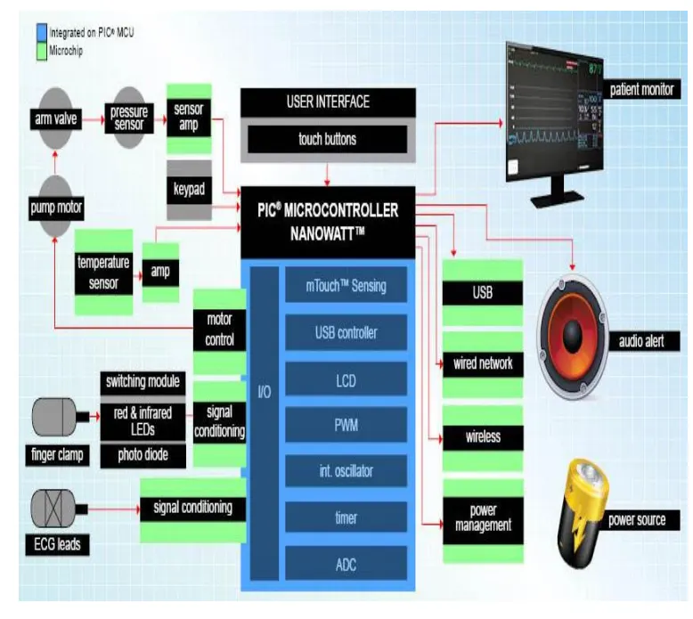
Internal Diagram / Block diagram of a multi-parameter patient monitor
3. What types of processing is requirement is required to catered in the design? Explain them briefly.
Processing requirement required to cater in the design:
- All the data will be acquired by single board computer or digital signal processing board.
- Patient monitor or multi-parameter monitoring system are used for critically-ill patients and commonly used in ICUs.
- Processing is required to be cater in the design of multi-parameter monitoring system in order to remove the unwanted noise and artifacts in the signal.
- Signal from different physiological parameters faces the following artifacts and the process of removal of each artifact is mentioned:
- Interference from the power line(PL):-
- Power line interference is a major concern. So, interfering voltages in the ECG signal will have a frequency component of 50Hz or 60Hz. This interference may be due to stray effect of all the ac on the patient or because of the ac waves due to the loops in the patient cables which will be running around the electrodes to the acquisition system or the measuring system.
- Also, there may be improper contact of the electrode with the skin surface area. This will also add some artifact. So processing has to be done to remove these kinds of PL interferences. If we use an analog or digital filter, this kind of filtering will even remove the 50Hz component of ECG signal. So, utmost care has to be taken.
- If we use a notch filter we will lose the components of 50Hz and also the nearby components of the ECG signal due to the response of the notch filter.
- We can remove noises by filtering or by avoiding at the source of pickup itself, we can try to avoid these noises and try to eliminate at the source itself, so we will not have to do any filtering and losing any important information from the signals.
- Other mode is the Common Mode Rejection Ratio, because the person on which measurement is done will also pickup the PL interference and it will interfere with ECG signals. They can also be removed by Common Mode Rejection Ratio(CMRR).
- There will be large amount of offset voltages. These offset voltages also get manifested into a form of a noise.
- There are two components-one is 50Hz interference from the PL and dc offset potential which will be created due to difference in the electrodes. These electrodes will have some offset which will be manifested into the signal.
- So, the common mode noises will be removed as body itself acting as an antenna by means of capacitive coupling to the main power lines which are nearby.
- Next is ECG cables acting as antenna & picking up the capacitive coupled signals from the power lines.
- One method which is used here to avoid them at the source itself is by driven right leg concept. So here, we will decrease the degree of cancellation of the common mode signals. A fraction of a signal is taken and then it will be inverted and then driven back to the patient through an electrode which will be placed on the right leg. This electrode is known as the right leg drive or the driven right leg. Return current will only be of the order of few microamperes or much lesser than that which will improve the CMRR of amplifiers.
- The two common mode voltages of body are sensed by two averaging resistors. Basically in ECG if we are acquiring Lead I, now we take from right arm and left arm, inputs will be given to summing amplifier.
- The summing will work as an inverting amplifier and it will give a current output which will be given the subject as an inverting input to remove all the common mode voltages which are present with signals of interest, i.e. ECG signal. This feedback will improve CMRR & also patient safety is its another advantage.
- So, in case there are any leakage currents and any high voltages between patient and the ground, the auxillary amplifier on the right leg will go into saturation and then will effectively unground the patient.
- Baseline Wander:
- Slow variation of baseline of ECG signal. Here the isoelectric line will be disturbed.
- This is caused due to respiration of a person. Here, the thorax will expand.
- Electrode will have movement w.r.t. movement of a person on the thorax region due to the expansion of the thorax.
- There will be disturbance in smooth ionic exchange, which is happening between the skin surface, the electrolyte and the electrode. This disturbance will get manifested into noise voltage.
- Since, we are disturbing the electrochemical equilibrium which is happening very smoothly.
- Baseline wander is a very low frequency signal & ECG will be modulated onto that slow varying respiration signal and this is not a desirable parameter and has to be removed before presenting to doctor for any diagnosis.
- The frequency content of the baseline wander is in the range of 0.5 Hz. However, increased movement of the body increases the frequency content of baseline wander. Since, the baseline signal is a low frequency signal therefore Finite Impulse Response (FIR) high-pass zero phase forward-backward filtering with a cut-off frequency of 0.5 Hz to estimate and remove the baseline in the ECG signal is used here.
- Motion Artifacts:
- Electrode motion artifacts are mainly caused by skin stretching which alters the impedance of the skin around the electrode. Motion artifacts resemble the signal characteristics of baseline wander, but are more problematic to combat since their spectral content considerably overlaps that of the PQRST complex. They occur mainly in the range from 1 to 10 Hz. In the ECG, these artifacts are manifested as large-amplitude waveforms which are sometimes mistaken for QRS complexes.
- Electrode motion artifacts are particularly troublesome in the context of ambulatory ECG monitoring where they constitute the main source of falsely detected heartbeats.
- One of the widely used techniques for removing the electrode motion artifacts is based on adaptive filters. The general structure of an adaptive filter for noise canceling utilized in this paper requires two inputs, called the primary and the reference signal. The former is the d(t) = s(t) + n1 (t) where s(t) is an ECG signal and n1(t) is an additive noise. The noise and the signal are assumed to be uncorrelated. The second input is a noise u(t) correlated in some way with n1 (t) but coming from another source. The adaptive filter coefficients wk are updated as new samples of the input signals are acquired. The learning rule for coefficients modification is based on minimization, in the mean square sense, of the error signal e(t) = d(t) − y(t) where y(t) is the output of the adaptive filter. A block diagram of the general structure of noise cancelling adaptive filtering is shown in figure 13 [10]. The two most widely used adaptive filtering algorithms are the Least Mean Square (LMS) and the Recursive Least Square (RLS).
- Interference from the power line(PL):-
4. What are the safety requirements to be catered in the design?
Safety Requirements
There are several safety requirements that should be considered in the design of a multi-parameter patient monitor:
-
Electrical safety: Patient monitors should be designed to meet electrical safety standards to prevent shock and electrocution. This includes ensuring that the device is properly grounded, has proper insulation, and is equipped with overcurrent protection.
-
Data security: Patient monitors collect and transmit sensitive patient data, so it is important to ensure that this data is secure and not accessible to unauthorized individuals. This can be achieved through the use of encryption and secure communication protocols.
-
Alarm safety: Patient monitors should be equipped with alarms to alert medical staff to any changes in a patient's condition. It is important to design these alarms in a way that minimizes the risk of false alarms, as well as ensures that they are loud enough to be heard in a busy hospital environment.
-
Display readability: The display on a patient monitor should be easy to read, even in low light conditions. The text and graphics should be large enough to be easily visible from a distance.
-
Durability: Patient monitors should be designed to withstand the rigors of a hospital environment, including spills, drops, and other accidental damage.
-
User interface: The user interface on a patient monitor should be intuitive and easy to use, to minimize the risk of user error. It should also be clearly labeled and include instructions for use.
- Patient safety considerations should be taken. Faulty medical equipments may lead to electric shock (micro and macro shocks). Steps needed to be taken to avoid electric shocks. Safety needs to be ensured for patient, doctor, nurses and operator.
- The operator needs to be experienced so that he/she can handle the equipment properly. Fail;ure to operate the equipment may lead to loss of life.
- Standards needs to be established and followed accordingly.
- The device should be reliable, simple and capable of withstanding all environments.
- The device should withstand additional factors like transportation, vibration, etc. and environmental factors like weather, rain, etc.
5. How is the device proposed to be qualified? How is device calibration proposed to be done?
Standards of Biomedical devices
The qualification process
The following criteria are proposed for the device's qualification:
>The monitor must successfully complete a maintenance schedule by trained professionals in order to be qualified; otherwise, it could become inoperable and endanger the patient's health.
>To conduct tests on insulation resistance, leakage current, and protective ground impedance replacing the ECG cable and lead wires if they are worn out or damaged
should check for damage to the cable and transducer; if either has deteriorated, future use is not permitted.
The monitor must be calibrated prior to factory sale in order to prevent future calibration requirements.
- The ECG signal amplification accuracy can be verified by the built-in 1 mV calibration signal
- The pressure management accuracy and air leakage in the pneumatic system can be verified by a built-in pressure verification function and a precision pressure meter
- A specific calibration curve known as the R curve should be selected when SPO2 simulator precision accuracy is verified
- The battery should be used once a month to ensure its power capability and long service life. Recharge it after it ran out of its power capacity.
-
whether any particular me equipment or me system is required to be provided with alarm systems;
-
the particular circumstances which initiate an alarm condition;
-
the allocation of priorities to a particular alarm condition; or
-
the means of generating alarm signals.
IEC 60601-1
-
"the general standard" designates IEC 60601-1 alone;
-
"this collateral standard" designates IEC 60601-1-8 alone;
-
"this standard" designates the combination of the general standard and this collateral standard.
Other IEC Standards
- IEC 60417, Graphical symbols for use on equipment
- IEC 60601-1:2005, Medical electrical equipment — Part 1: General requirements for basic safety and essential performance
- IEC 60601-1-6:, Medical electrical equipment — Part 1-6: General requirements for basic safety and essential performance — Collateral standard: Usability
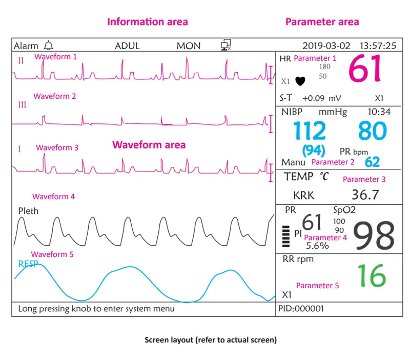
6. Draw the screen layout for displaying the parameters on the display?
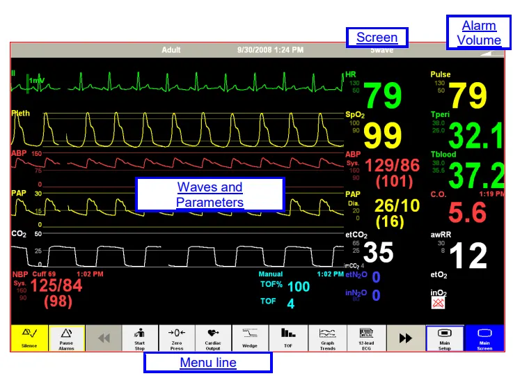
7. How is the data proposed to acquired and stored in the database?
The information that is suggested to be acquired and stored in the database:
>All the sensors will be interfaced via a single board data acquisition and control system.
>A single-board computer or digital signal processing board will be used to collect all the data.
>Four key elements make up contemporary digital data acquisition systems, which together make up the whole measuring chain of physical phenomena:
- Sensors
- Signal Conditioning
- Analog-to-Digital Converter
- Computer with DAQ software for data logging and analysis
>The A/D converter subsystem and external sensors are typically interfaced by numerous channels of signal conditioning circuitry found in data acquisition systems.
>Data collection systems will primarily use a variety of sensors to measure the physical characteristics of the multi-parameter monitoring system.
>A data acquisition system's main function is to gather and store data. But in this case, it is also meant to offer data visualisation and analysis in real-time and after recording.
- Sensors or Transducers
- The measurement of a physical phenomenon, such as the temperature, the level of a sound source, or the vibration occurring from constant motion, begins with a sensor. A sensor is also called a transducer. A sensor converts a physical phenomenon into a measurable electrical signal.
- Sensors are used in our everyday lives. For example, the common mercury thermometer is a very old type of sensor used for measuring temperature. Using colored mercury in a closed tube, it relies on the fact that this chemical has a consistent and linear reaction to changes in temperature. By marking the tube with temperature values, we can look at the thermometer and see what the temperature is with limited precision.
- Depending on the type of sensor, its electrical output can be a voltage, current, resistance, or another electrical attribute that varies over time. The output of these analog sensors is typically connected to the input of a signal conditioner.
- Different sensors used here are:
- Thermistor for Temperature measurement.
- Pressure transducer for Blood pressure measurement.
- Bioelectric transducers for ECG measurement and Heart Rate measurement.
- Respiratory rate is acquired from ECG only.
- Optical transducers for Pulse oximetry measurement and pulse rate measurement.
- Signal Conditioners:
- Signal conditioners are working on for taking the output from analog sensors and preparing them to be sampled digitally.
- If we continue the example of the thermistor. The signal conditioning circuitry needs to linearize the output from the sensor as well as provide isolation and amplification to bring the very small voltage up to a nominal level for digitizing.
- Each signal conditioning circuitry is designed by the manufacturer to perform the elemental normalizing of the sensor output to ensure its linearity and fidelity to the source phenomena, and prepare it for digitizing. And since every sensor type is different, the signal conditioners must conform perfectly to them.
- Isolation Barrier:
- Sometimes also referred to as galvanic isolation, electrical isolation is the separation of a circuit from other sources of electrical potentials. This is especially important with measuring systems because most signals exist at relatively low levels, and external electrical potentials can influence the signal quality greatly, resulting in wrong readings. Interfering potentials can be both AC and DC in nature.
- Isolation amplifiers are used here to achieve electrical isolation, to break the ohmic continuity between input and output of amplifier. They have separate supply voltage source and have different grounds on either side of isolation barrier.
- For example, when a sensor is placed directly on an article under test, (e.g. a power supply) which has potential above ground (i.e., not at 0V), this can impose a DC offset on the signal of hundreds of volts. Electrical interference or noise can also take the form of AC signals created by other electrical components in the signal path or in the environment around the test. For example, fluorescent lights in the room can radiate 400Hz which can be picked up by very sensitive sensors.
- This is why the best data acquisition systems have isolated inputs - to preserve the integrity of the signal chain and ensure that what the sensor outputs is truly what has been read.
- Here we use an optical isolator. It can be achieved by using optical source and detector. Patient is electronically connected to neither the hospital line nor to the ground line. As separate battery operated circuit supplies power to the patient circuit and signal of interest will be converted into a light source and light falls on a phototransistor at output side which converts the light again to electrical signal and its linearity will be maintained. No modulator or demodulator will be used here and signal is connected in optical way. It is a very cheap method of isolation. Isolation voltage is 800V between input and output.
- Analog-to-digital Convertor:
- The output of most physical measurement signal conditions is an analog signal. It is necessary to convert this signal to a series of high-speed digital values so that it can be displayed and stored by the data acquisition system. As such, an A/D card or A/D subsystem is used to convert this signal.
- There are a variety of ADC types, single convertor per channel ADC is used here because time constraint is very important here as we need all the parameters to be shown at the same time on the screen, no delay is acceptable in this.
- It is possible to align the signals on the time axis, because only one signal will be converted by one ADC at a time. Therefore, there will never be a time skew between channels.
- 24-bit ADCs are used in this data acquisition systems designed to make dynamic measurements.
- The rate at which the signals are converted is called the sampling rate. Certain applications, such as most temperature measurements, do not require a high rate since the measurands do not change very rapidly. However, AC voltages and currents, shock and vibration, and many other measurands require sample rates in the tens or hundreds of thousands of samples per second or more.
- Sampling rate follows the Nyquist theorem:
- Fs = 2Xfm
- where fm is the maximum frequency ,
- Fs is the sampling frequency.
>ADCs with high sample rates and amplitude axis resolution are the best for analysing dynamic signals like shock and vibration. Thermistors and other measurands with a large amplitude range but slow state changes benefit from low sample rates and good amplitude axis resolution. The 16-bit ADC used for temperature measurement.
>The usage of ADCs with anti-aliasing filtering (AAF) prevents measuring mistakes brought on by undersampling signals, which is a problem in all applications involving dynamic measurements. When a fast-changing signal is sampled too infrequently, aliasing occurs, producing a misleading signal.
Data Storage
>Modern data acquisition systems generally transfer data from the ADC subsystem to long-term storage using a solid-state hard disc drive (SSD or HDD). Additionally, writing the data to disc enables analysis of it once the test is finished.
>The majority of DAQ systems enable data export to several file formats for analysis using external software applications.
>Utilizing software from the hospital information system, the data is kept in HL7 format in the patient monitor (HIS). Data is transmitted from clients to servers, or from one patient monitor to the network's main system, using the network interface card (NIC). Each patient monitoring system may be distinguished from one another thanks to their unique Internet Protocol (IP) addresses.
8.Design ICU with 8 beds using the multi-parameter monitor and how is it proposed to be networked. How is the Central Nursing station proposed to be designed and explain in detail?
To design an ICU with 8 beds using a multi-parameter monitor, you would need to consider the following:
-
The layout of the ICU: The beds should be spaced out appropriately to allow for easy access and movement around the unit. You should also consider the location of the central nursing station, which should be easily accessible from all beds.
-
The multi-parameter monitors: These monitors should be placed at the head of each bed, within easy reach of the nursing staff. The monitors should be able to measure a range of vital signs, including heart rate, blood pressure, oxygen saturation, and respiration rate.
-
Networking: The multi-parameter monitors should be connected to a central monitoring system, which allows nursing staff to view the vital signs of all patients from a central location. This can be done using a wired or wireless network.
-
Central nursing station: The central nursing station should be designed to allow the nursing staff to easily view the vital signs of all patients, as well as access the patient's medical records and other information. This could be done using a computer system with multiple monitors, or a display board with individual screens for each patient. The central nursing station should also have a phone system and other communication tools to allow the nursing staff to communicate with other members of the healthcare team.
-
Additional considerations: Other factors to consider when designing the ICU include the need for storage space for medical supplies, the availability of electrical outlets for medical equipment, and the need for a separate area for consultations with families.
9. What type of network connectivity is proposed if the system is planned for remote monitoring?
> If this multi-parameter monitoring system is intended for remote monitoring, it can wirelessly connect to a mobile device or computer using Bluetooth, WiFi, or the Internet.
>Data is also kept in the cloud network, making it simple to access patient information and to store and retrieve upcoming readings as needed.
>Utilizing cloud computing allows for the centralization of data. The cloud can offer services across either public or private networks. It is LAN, MAN, and WAN compatible.
>It is an internet tool for processing, computing, customising, and manipulating data. It is a location for infrastructure, applications, and data storage. It offers services based on both hardware and software.
>With SaaS, you merely use the Internet to access software that is totally provided and managed by the cloud provider. Email, content management systems, productivity software, and business applications are examples of the kind of software that can be used. SaaS is the least complex to set up, but it also offers the least degree of control and flexibility over how the system works and what data can be posted to or downloaded from the cloud.
There are a few different types of network connectivity that could be used for remote patient monitoring, depending on the specific requirements of the system and the needs of the patients being monitored. Some options might include:
-
Wide Area Network (WAN): A WAN can be used to connect devices and systems over a large geographic area, such as a country or even globally. This could be useful for remote patient monitoring if patients are located in different parts of the world and need to be connected to a central monitoring system.
-
Local Area Network (LAN): A LAN can be used to connect devices and systems within a small geographic area, such as a hospital or clinic. This could be useful for remote patient monitoring if patients are located within the same facility and need to be connected to a central monitoring system.
-
Wireless Network: A wireless network can be used to connect devices and systems using wireless technology, such as Wi-Fi. This could be useful for remote patient monitoring if patients need to be connected to a central monitoring system but are not able to be connected via a wired connection.
Ultimately, the best type of network connectivity for a remote patient monitoring system will depend on the specific needs and requirements of the system and the patients being monitored.
10.Since this device is planned to be used in ICU, what types of alarms are proposed and when are they going to be generated.
In an intensive care unit (ICU), patient monitoring devices are typically used to continuously monitor a variety of vital signs, such as heart rate, blood pressure, respiratory rate, and body temperature. These devices may be programmed to generate alarms if any of these vital signs fall outside of a predetermined range. For example, an alarm might be generated if a patient's heart rate falls below a certain threshold or if their blood pressure rises above a certain level.
In addition to alarms for vital signs, patient monitoring devices in an ICU may also be programmed to generate alarms for other events or conditions. For example, an alarm might be generated if a patient's oxygen saturation falls below a certain level, if their blood glucose level becomes too high or too low, or if they experience a seizure.
It is important to note that while alarms can be helpful in alerting medical staff to potential issues, they can also be a source of noise and distractions. As a result, it is important to carefully consider the types of alarms that are necessary and to carefully set the thresholds at which they are triggered.
In an intensive care unit (ICU), patient monitors are typically used to monitor a variety of physiological parameters, such as heart rate, blood pressure, respiratory rate, and oxygen saturation. These monitors are designed to alert healthcare providers if a patient's vital signs fall outside of a predetermined range, indicating a potential health issue.
The types of alarms that are generated by a patient monitor in an ICU can vary depending on the specific monitor and the parameters it is monitoring. Some common types of alarms that might be generated include:
-
High/low heart rate alarms: These alarms are triggered when a patient's heart rate falls outside of a predetermined range, which may indicate a potential cardiac issue.
-
High/low blood pressure alarms: These alarms are triggered when a patient's blood pressure falls outside of a predetermined range, which may indicate a potential cardiovascular issue.
-
High/low respiratory rate alarms: These alarms are triggered when a patient's respiratory rate falls outside of a predetermined range, which may indicate a potential respiratory issue.
-
Low oxygen saturation alarms: These alarms are triggered when a patient's oxygen saturation falls below a predetermined level, which may indicate a potential respiratory or cardiac issue.
It's important to note that the specific thresholds for these alarms will depend on the patient's age, medical history, and other factors. The alarms are generally set to be triggered when a patient's vital signs fall outside of a normal range, but they may be customized based on the needs of the individual patient.
To transfer data to a removable storage device such as a pen drive, you can use the following steps:
- Connect the storage device to your computer using a USB cable.
- Wait for the device to be recognized by your operating system.
- Locate the files or folders you want to transfer.
- Drag and drop the files or folders onto the removable storage device icon on your computer.
Alternatively, you can also use the "Copy" and "Paste" commands to transfer the data.
As for the data formats that are supported, it will depend on the device you are transferring the data to and its capabilities. Most storage devices support common file formats such as text files, images, and videos. It is always a good idea to check the documentation or specifications for the device to see which file formats it supports.