Project 1
Aim: To Model & Design a Proposed Coil Centre, Chennai using STAAD. Pro for following input from Client
Design only a Main Frame with Lean (Grid 2) & Gable Frame without Lean (Grid 15)
Introduction:
The portal frame structure is mainly composed of steel columns and roof beams, and the frame is a plane loading system. To ensure longitudinal stability, which column bracing and roof bracing will arrange.
The portal frame divided into several forms, 1. Typical portal steel frame. 2. Steel frame with the crane. 3. Steel frame with mezzanine structure.
Bracing Structure
The portal frame, purlin Bracing system and the metal cladding rely on each other through reliable connection and support.
The main structure of the portal frame load-bearing structure divided into two types according to the kind of the rigid frame: the clear span structure without interior columns and the multi-span continuous structure with interior columns.According to the specific project, it can also be used in single and multiple slopes, as well as in different spans and heights.
The main functions of the bracing system are:
1) The strut beam transmits the longitudinal horizontal force.
2) The horizontal bracing resists the horizontal force transmitted between the columns and roof beams.
3)Flange Bracing use to keep the stability of the outer plane
4) All bracing systems, together with purlin or wall girt and portal frames, which form a space system, which ensures the overall function of the space of the structure, bear, and transfer horizontal loads, and ensure the stability and convenience during the installation.T
Purlin and Wall Girt
The main component types of purlins and wall girt are C-type or Z-type steel, and the size of the cross-section needs to determine through the load calculation. Compared with the Z-section, the mechanical properties of the C-section are quite different, C section steel connects to the portal frame bolted.
The different types of loads that are to be considered
- Dead load
- Live load
- Wind load
- Earthquake load
Dead Loads (D): The PIP Structural Design Criteria prescribes specific dead loads for pipe racks. Pipe racks and their foundations should be designed to support these loads applied on all available rack space, unless other criteria is provided by the client.
Structure dead load (Ds): The weight of materials forming the structure and all permanently attached appurtenances. This includes the weight of fire protection material, but does not include the weight of piping, cable trays, process equipment and vessels.
Operating dead load (Do): The operating dead load is the weight of piping, piping insulation, cable tray, process equipment and vessels plus their contents (fluid load). The piping and cable tray loads may be based on actual loads or approximated by using uniform loads.
Empty dead load (De): The empty weight of piping, piping insulation, cable tray, process equipment and vessels. When using approximate uniform loads, 60% of the operating dead load for piping levels is typically used. Engineering judgment should be used for cable tray levels.
Test dead load (Dt): The empty weight of the pipes plus the weight of the test medium.
Live load: Live load is one of the gravity load imposed by liquid or viscous materials in pipes during the operation along with which the human load is also added to it. Live load is defines as the load which is produced by the use and the occupancy of the structure thus not including any kind of construction or the environmental loads. Live load generally comes around the platform area, staircase and at the places where the access for the maintenance is provided.
Wind Load: Transverse wind load on structural members, piping, electrical trays, equipment, platforms, and ladders should be determined in accordance with project approved design code. Longitudinal wind should typically be applied to structural framing, cable tray vertical drop (if any), large dia pipes vertical drop (if any) and equipment only. The effects of longitudinal wind on piping and trays running parallel to the wind direction should be neglected.
Earthquake Loads: Earthquake loads in the vertical, transverse, and longitudinal directions should be determined in accordance with the project design criteria. Vertical, transverse, and longitudinal seismic forces generated by the pipes, raceways, supported equipment, and the pipe rack structure should be considered and should be based on their operating weights. Pipes must be evaluated for seismic loads under both full and empty conditions and then combined with the corresponding gravity loads.
Given :
|
Building Parameters |
|||||
|
1 |
Building Width |
30000.00 mm |
Client |
Out to Out of Steel |
|
|
2 |
Width Module |
Clear Span |
Client |
||
|
3 |
Building Length |
140000.00 mm |
Client |
Center to Center of Steel Column |
|
|
4 |
Building Height |
11100.00 mm |
Client |
Clear Height from FFL |
|
|
5 |
Roof Slope |
1:10 |
Client |
||
|
6 |
Column Base |
Fixed Base |
Assumed |
To control Deflection |
|
|
7 |
Bay Spacing (in mm) Main frame with Rafters |
14@10000 |
Client |
Center to Center of Steel Column |
|
|
8 |
Roof Bracing |
Diagonal Angle Bracing |
Client |
||
|
9 |
Wall Bracing |
Portal Bracing and above Angle Bracing |
Client |
Up to 6.5m Portal Bracing |
|
|
10 |
End Wall Typea` |
Rigid Frame |
Assumed |
|
|
|
GENERAL PARAMETERS |
|||||
|
Loads & Design |
|||||
|
1 |
Dead Load |
0.14 KN/m2 |
Assumed |
||
|
2 |
Coll Load |
0.15 KN/m2 |
Client |
False ceiling load for Roof extension alone |
|
|
3 |
Live Load |
0.75 KN/m2 |
Code |
IS 875 (Part 2) -2015 |
|
|
Sl.No |
Parameter |
Value |
Data From |
Remark |
|
|
4 |
Wind Load |
Wind Speed |
180 KMPH |
Code |
IS 875 (Part 3) - 2015 |
|
K1 = |
1.00 |
Code |
IS 875 (50 years of mean probable design life |
||
|
K2 = |
0.94 |
Code |
IS 875 (Terrain Category 3) |
||
|
K3 = |
1.00 |
Code |
IS 875 (Upwind slope is less than 3°) |
||
|
K4 = |
1.15 |
Code |
IS 875 (Cyclone Zone) |
||
|
Building Condition |
Medium Permeability |
Code |
IS 875 (Part 3) - 2015 |
||
|
Wind co-efficients calculated as per |
Code |
IS 875 (Part 3) - 2015 |
|||
|
5 |
Seismic Zone |
Zone III |
Code |
IS 1893-2015 (Part 4) |
|
|
6 |
Loads applied as per |
IS 875 - 2015 |
Client |
||
|
7 |
Primary Member design |
IS 800 : 2007 |
Client |
||
|
8 |
Cold Form Design |
AISI 2001 |
Assumed |
||
Procedure:
Open STAAD and units for the loads and the distance are setup .
The coordinates are added in order to model the structure.
Beams are connected from node to node to frame a frame.
The supports like fixed or pinned are defined with the help of the support definition.
The end and the start moment for the bracings and the truss members are released so that they take up only the axial forces.
member properties are assigned to the beams
The L.L and D.L that are acting on the structure are added by defining the D.L and L.l cases.
The wind load and the EQ load are defined
Then the design load and EQ load are defined
Then the design parameters for the steel as well as concrete members are defined.
Structure is analysed and then checked for any failure members
Section view of the model
For main frame and gable frame
For area 1-30m width
Roof slope =1/10=0.1
Height of roof inn top level =1.5m
Add walls and add wall sheeting and roof sheeting
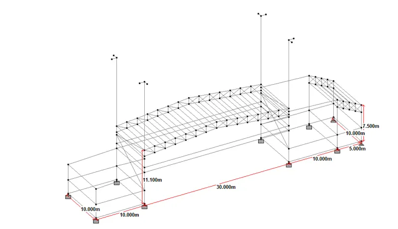
Go to properties and section database and add and assign section to the structure
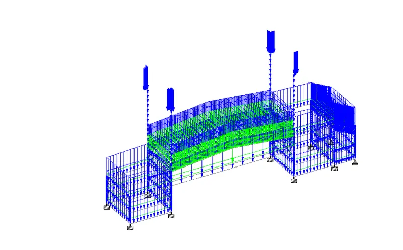
3D view of the entire structure
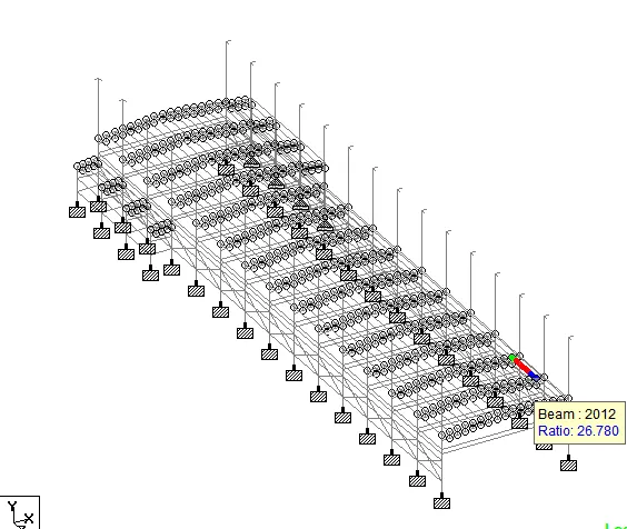
Section view of one bay
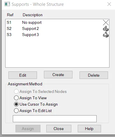
Go to support and create support and add and assign support for fixed and pinned base.
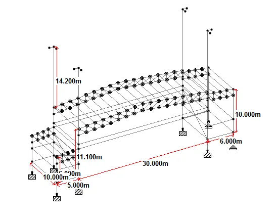
Defining of the member property and support
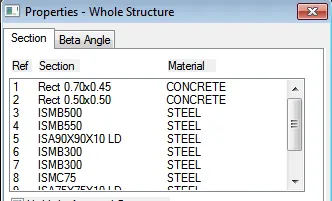
Load calculation:
Wind load
Basic wing speed (Vb)=50m/s
Total length of the industrial building for area 1 = 140m
Width of the industrial building for area 1 = 30m
Height of the industrial building for area 1 = 11.1 m
Risk factor,K1=1(designed for 50 year life span of structure)(table 1 of IS 875part 3)
Terrain category in this project is category 3.
K2 for 7m height =0.94
K3 the topography factor as per IS code is 1
K4 the cyclone factor =115
Design wind speed (vz)=Vb*K1k2*k3*k4
=50*1*0.94*1*1.15
=54.05m/s
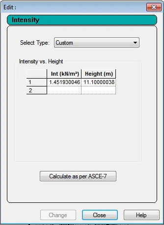
Deisgn wind intensity(Pz) = 0.6*(Vz^2)
=0.6*54.05^2
= 1.75KN/m^2
Wind load calculation with the internal pressure and succession
WL+X+CIP = 1.75*11.1+0.5-0.9=19.025KN/m
WL-X-CIP = 1.75*11.1-0.5-0.9=18.025kN/m
WL+Z+CIP=1.75*11.1+0.5-0.8=19.125kN/m
WL+Z-CIP=1.75*11.1-0.5-0.8=18.125KN/m
Seismic load
EQ+X
EQ-x
EQ+z
EQ-z
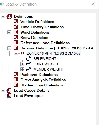
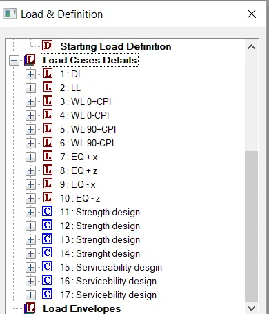
 Go to laod combinations and add as per stength design and servicebility criteria
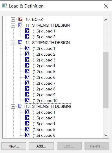
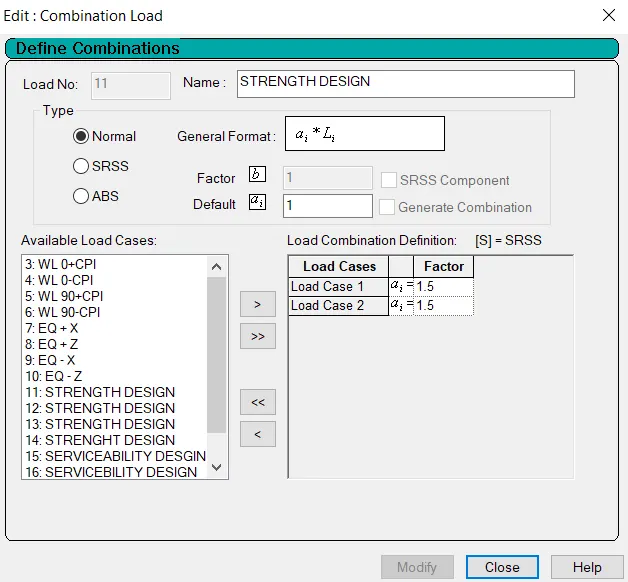
Go to edit combination load
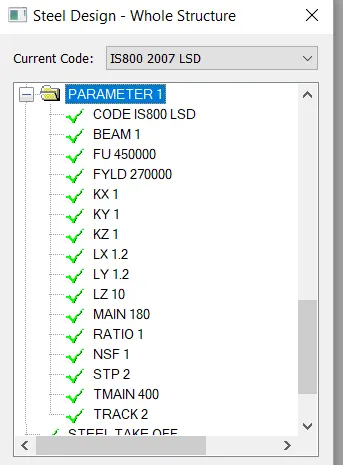
Go to design and add parameters using IS 800:2007
After run analysis and check deflection and section safe results.
For Gable frame and gable frame
Go to STAAD and define nodes and beams
Go to translation assign bay
For gable frame we analysis and design for one frame
- For area 1-30m width
- Roof slope =1/10=0.1
- Height of roof inn top level =1.5m
- Add walls and add wall sheeting and roof sheeting
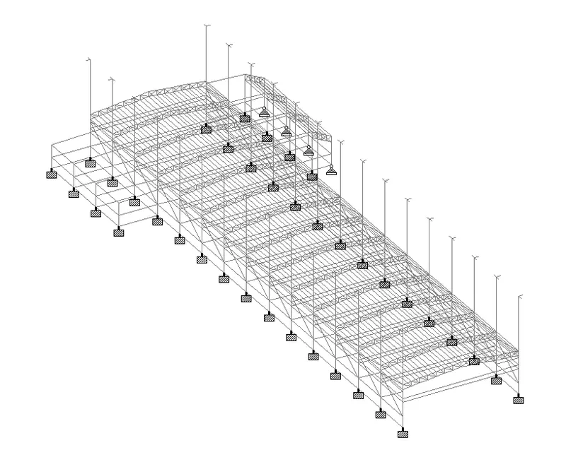
Go to properties and section database and add and assign section to the structure
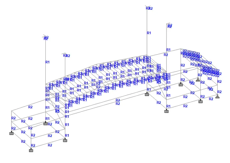
Go to support and create support and add and assign support for fixed and pinned base.
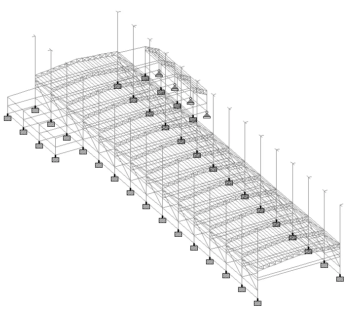
Load calculation:
Design wind speed =Basic wing speed (Vb)=50m/s
Total length of the industrial building for area 1 = 140m
Width of the industrial building for area 1 = 30m
Height of the industrial building for area 1 = 11.1 m
Risk factor,K1=1(designed for 50 year life span of structure)(table 1 of IS 875part 3)
Terrain category in this project is category 3.
K2 for 7m height =0.94
K3 the topography factor as per IS code is 1
K4 the cyclone factor =115
Design wind speed (vz)=Vb*K1k2*k3*k4
=50*1*0.94*1*1.15
=54.05m/s
Deisgn wind intensity(Pz) = 0.6*(Vz^2)
=0.6*54.05^2
= 1.75KN/m^2
Wind load calculation with the internal pressure and succession
WL+X+CIP = 1.75*11.1+0.5-0.9=19.025KN/m
WL-X-CIP = 1.75*11.1-0.5-0.9=18.025kN/m
WL+Z+CIP=1.75*11.1+0.5-0.8=19.125kN/m
WL+Z-CIP=1.75*11.1-0.5-0.8=18.125KN/m
Seismic load
EQ+X
EQ-x
EQ+z
EQ-z
Go to laod combinations and add as per stength design and servicebility criteria
Go to edit combination load
Go to design and add parameters using IS 800:2007
After run analysis and check deflection and section safe results.