Project 1
| PROJECT - 1 |
___Q1___
AIM : To design a battery pack for a car roughly 150 kW with 120 V.
OBJECTIVE : a. Design the battery pack configuration.
b. Draw the BMS topology for this battery pack.
THEORY :
|
Cell Data : |
Chemistry - NMC Nominal Voltage - 3.6 V Nominal Current - 3500 mAh / 3.5 A |
|
Battery Pack Data : |
Rated Voltage - 120 V Rated Power - 150 kW `Rated Current = ( Rated Power )/ (Rated Vol\tag\e)` `= (150 * 1000)/ 120 = 1250 A` |
- Number of cells in Series is calculated according to Voltage rating.
| `Number of Cells i\n Series = (Rated Bat\tery Vol\tag\e)/(Nomi\nal Cell Vol\tag\e)` |
`Number Of Cells i\n Series = (120)/3.6 = 33.33`
Two cases are considered to get the Number of Cells in Series a whole number.
| CASE 1 | CASE 2 |
|
- Rounding off to lower digit. - Cells in series = 33. - `therefore`voltage capacity = 33 * 3.6 = 118.8 V |
- Rounding off to higher digit. - Cells in series = 34. - `therefore`voltage capacity = 34 * 3.6 = 122.4 |
Since the voltage capacity in CASE 1 is less than rated battery capacity, neglecting CASE 1 and choosing CASE 2. i.e. 34 cells.
- Number of cells in Parallel is calculated according to Amperage rating.
| `Number of Cells i\n Parall\el = (Rated Bat\tery Current)/(Nomi\nal Cell Current )` |
`Number of Cells i\n Parall\el = 1250 / 3.5 = 357.14`
Two cases are considered to get the Number of Cells in Parallel a whole number.
| CASE 1 | CASE 2 |
|
- Rounding off to lower digit. - Cells in Parallel = 357. - `therefore`current rating = 357 * 3.5 = 1249.5 A |
- Rounding off to higher digit. - Cells in Parallel = 358. - `therefore`current rating = 358 * 3.5 = 1253 A |
Since the Current Rating in CASE 1 is less than required by the battery capacity, neglecting CASE 1 and choosing CASE 2. i.e. 358 cells.
So, Number of Cells in Series = 34.
Number of Cells in Parallel = 358.
RESULT :
a. The Battery Pack configuration is 34S358P.
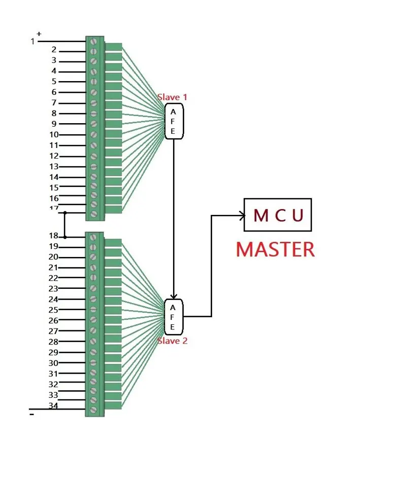
b. BMS topology will be Master-Slave as the number of cells in series is more than 18.
 |
CONCLUSION :
Thus a battery configuration of 34S358P with Master-Slave BMS topology is designed for car of 150 kW and 120V.
___Q2___
AIM : To build a 3S2P battery pack configuration with generic battery block using Matlab/Simulink.
THEORY :
The meaning of 3S2P battery pack configuration is 3 cells in Series & 2 cells in Parallel.
Hence total number of cells = 3*2 = 6.
Blocks Used : -
|
1 - Battery Block |
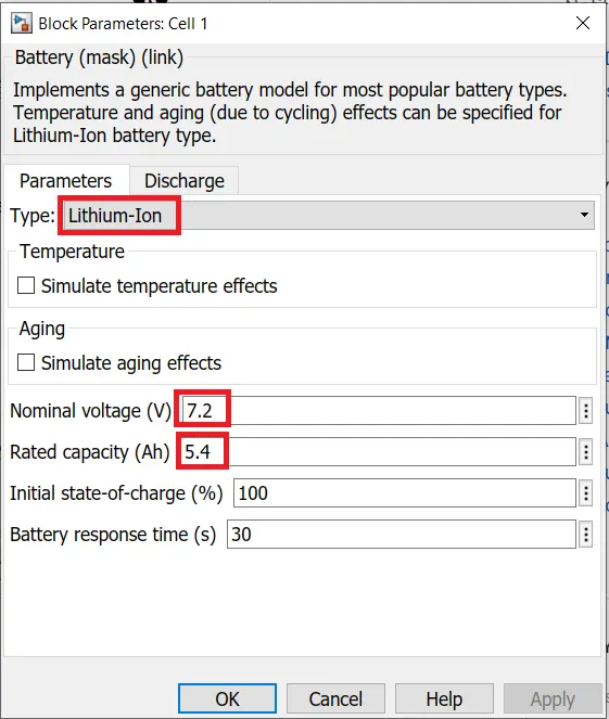
It implements a generic battery block for most popular battery types.
Nominal Voltage of the Battery Pack = Number of Cells in Series * Nominal cell voltage = 3 * 7.2 = 21.6 V Rated Capacity of Battery Pack = Number of Cells in Parallel * Rated Capacity of cell = 2 * 5.4 = 10.8 Ah Overall Voltage of Battery Pack = Maximum cell voltage * Number of cells in series = 8.3 * 3 = 24.9 V |
||
|
2 - Bus Selector Block |
- This blocks accepts a bus as input and outputs the elements selected by user separately. - In this model Measurement Bus from battery/cell is taken and connected with scope for 3 elements viz. SOC, Voltage & Current. |
||
|
3 - Controlled Current Source Block |
- It converts its input signal into an equivalent current source. - The current generated is driven by the input signal of the block. |
||
|
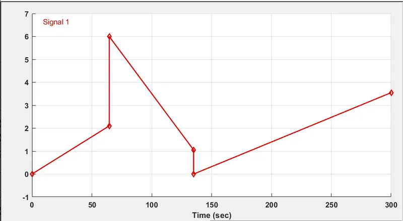
4 - Signal Builder Block |
- It creates interchangeable groups of piecewise linear signal source. - Signal built for this model is shown below :
|
||
|
5 - Powergui Block |
- It sets the simulation type, simulation parameters and preferences. - For this model continuous simulation type is selected. |
||
|
6 - Voltage Measurement Block |
It is ideal voltage measurement block. |
||
|
7 - Scope |
It displays results in graphical format. |
||
| 8 - Display Block | It displays the input values. |
CONSTRUCTION :
1 - Cells are selected from Simscape/Electricl/Specialised Power Systems/Sources library of Simulink.
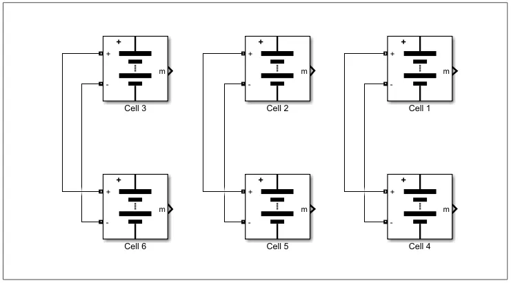
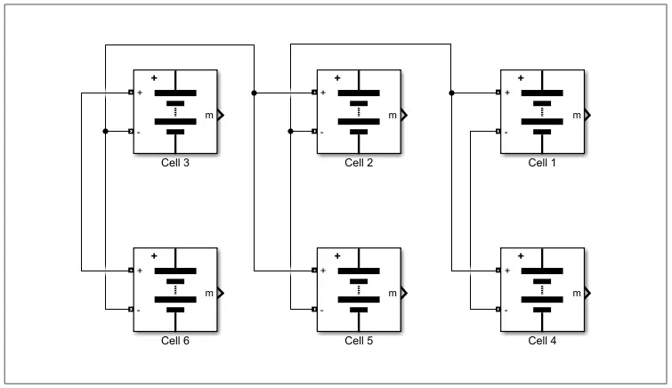
2 - Cells are first connected in Parallel i.e. 2P configuration.
Cells are connected with same polarity i.e. (+ with +) & (- with -).
3 - Cells are then connected in Series i.e. 3S configuration.
Cells are connected with opposite polatiry. i.e. (+ with -).
|
4 - |
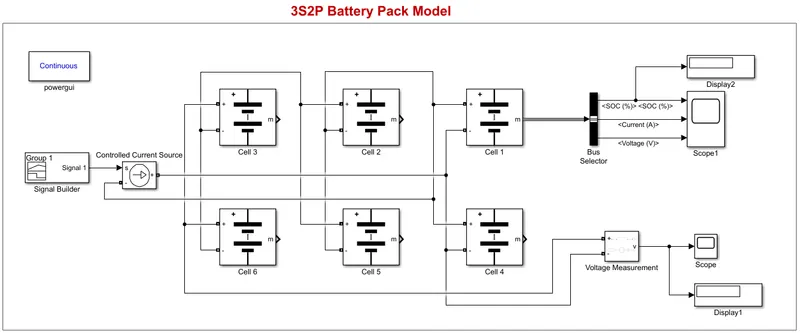
Final Simulink Model of 3S2P Configuration. Bus selector block is connected to first cell to take measurements of the cell. Voltage Measurement block is connected to + & - terminal of the pack to measure battery voltage. Signal Builder block is connected to battery pack via controlled current source, which acts as a load to the pack. |
RESULT :
The model is run for 300 seconds.
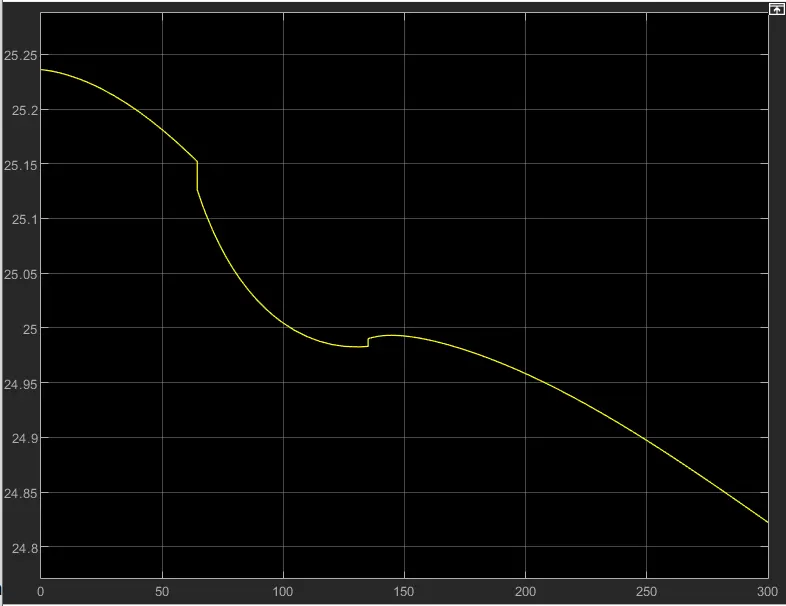
- Overall Voltage of the Battery Pack is shown below. i.e. 24.9 V
- Cell Measurements are shown below.
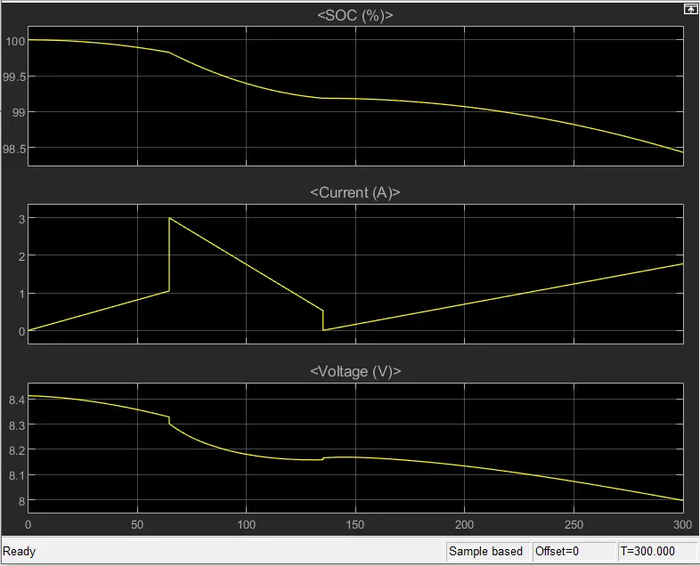 |
SOC % : 98.43%
Voltage : 24.82 V
|
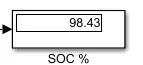
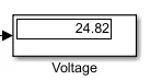
- SOC reduces to 98% when the model is simulated for 300 seconds. Small regeneration is seen around 150 seconds.
- The current is dependent upon the load which is modelled using a signal builder block.
- Nominal voltage of 8.3 V is reduced to around 8 V.
CONCLUSION :
A simulation of 3S2P configuration Battery pack with voltage 24.9 V is done successfully.
-----------------------------------------------------------------------------------------------------------------------------