PREPROCESSING ON REAR WHEEL SUSPENSION MODEL OF AN AUTOMOBILE USING ANSA
AIM: To perform preprocessing on rear wheel suspension model using ANSA Software.
OBJECTIVE:
- Geometry cleanup on given suspension assembly model.
- To extract middle surface, when thickness is uniform and less than 5mm.
- To provide appropriate mesh parameters and quality criteria parameter.
- To perform shell meshing with element type mixed as per given quality criteria.
- Performing shell mesh with element type Tria only for non-uniform thickness components.
- Performing tetrahedral volume mesh as per given quality criteria.
- To use CBAR 1D element for representing suspension spring.
- Deploying appropriate connections to connect the components.
- To perform symmetry command to reflect half-finished model to the other side.
- Assigning thickness, in order to make shell as solid.
CAD MODEL:
First, we have to Import the appropriate CAD file i.e. automobile rear wheel suspension assembly in ANSA software by using GUI option. Once model is opened, it will look like as shown in picture below:
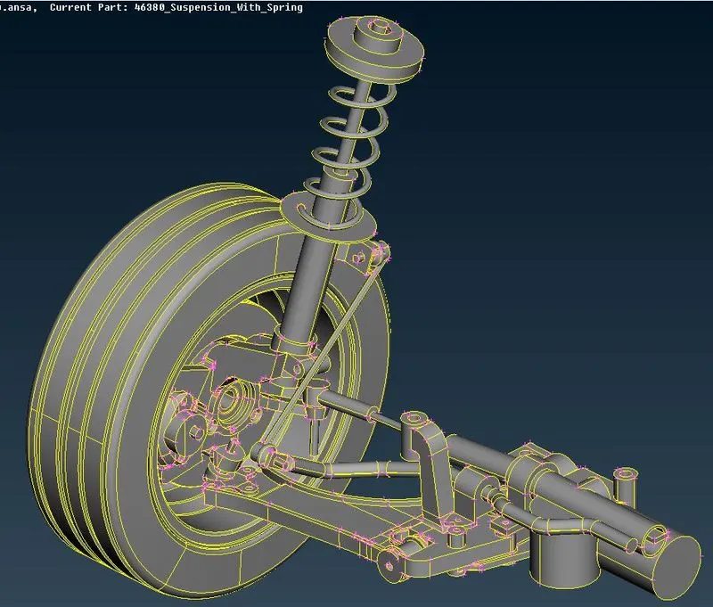
Figure 1: CAD model of rear wheel suspension assembly
Now, we have to assign new property identity for each and every component. Once new PID is assigned, model will look like as shown in picture below:
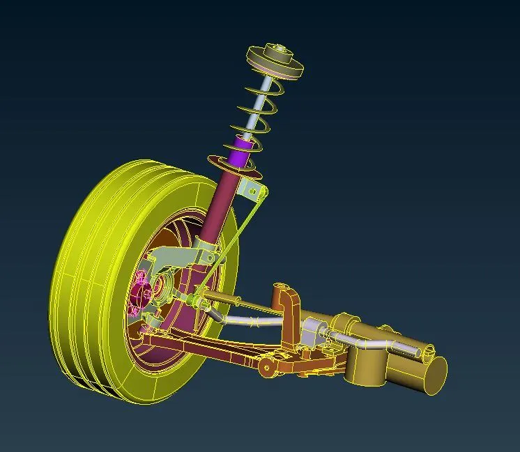
Figure 2: CAD model of rear wheel suspension assembly
PROCEDURE:
1. Geometry cleanup
Before proceeding to discretization of model, we have to make sure that geometry is free from errors.
Ansa is having default check template, where we have to filter our model for given errors. In this case, we have to select all checks except Sharp edges and unmeshed macros.
In order to rectify geometrical errors, following steps have to follow:
Left click on “Checks” in Tools option ----> Select “Geometry” in options ---->set “Visible” for Execute on (It helps to automatically selecting the visible component in graphical window ----> Now click on Execute.
This function locates geometrical problems of the model such as needle faces, collapsed cons, triple cons, overlaps and cracks. Error generates will depend on selected ANSA Checks option in template as shown in picture below.
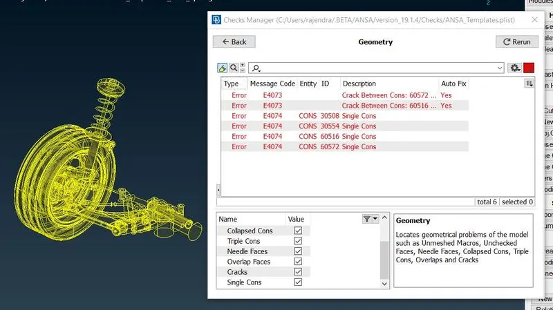
Figure 3: Geometry cleanup
As we can see ANSA generates a number of errors. In order to check any error, right click on the error which need to be check and select show only. Then it automatically identifies particular error location in the component. In order to fix these shown error, we have two options. Either we can use manual or auto Fix option. We will use auto fix because we noticed in check tab i.e. yes for Auto Fix, that means ANSA can fix these shown errors automatically.
As we know, we can proceed to next stage only if there are no geometrical error left. So we will rerun the geometry checkup macro until geometry is free from errors as shown in picture below:
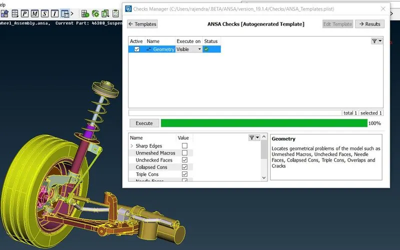
Figure 4: Geometry cleanup
Now geometry is free from errors. So we can proceed to further steps.
2. MID surface extraction
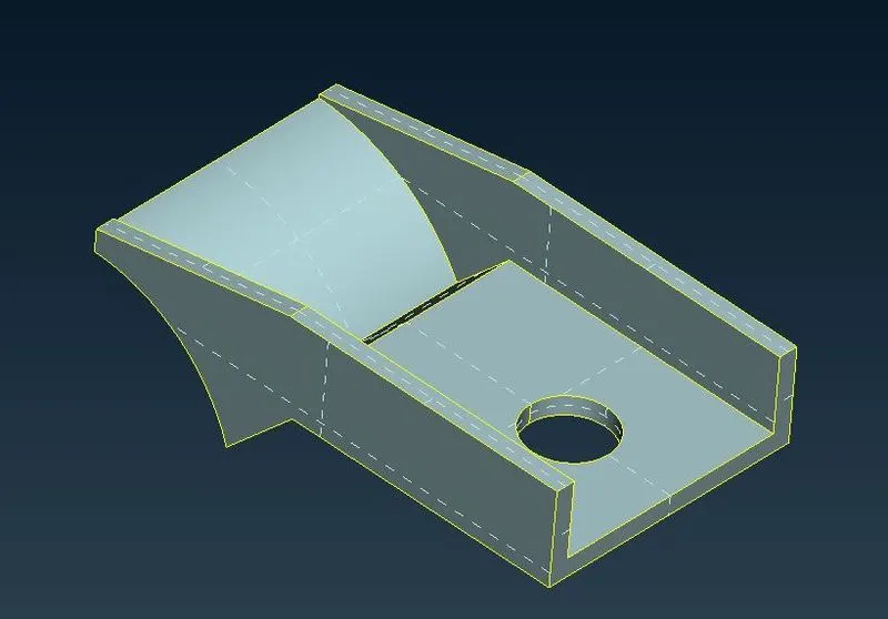
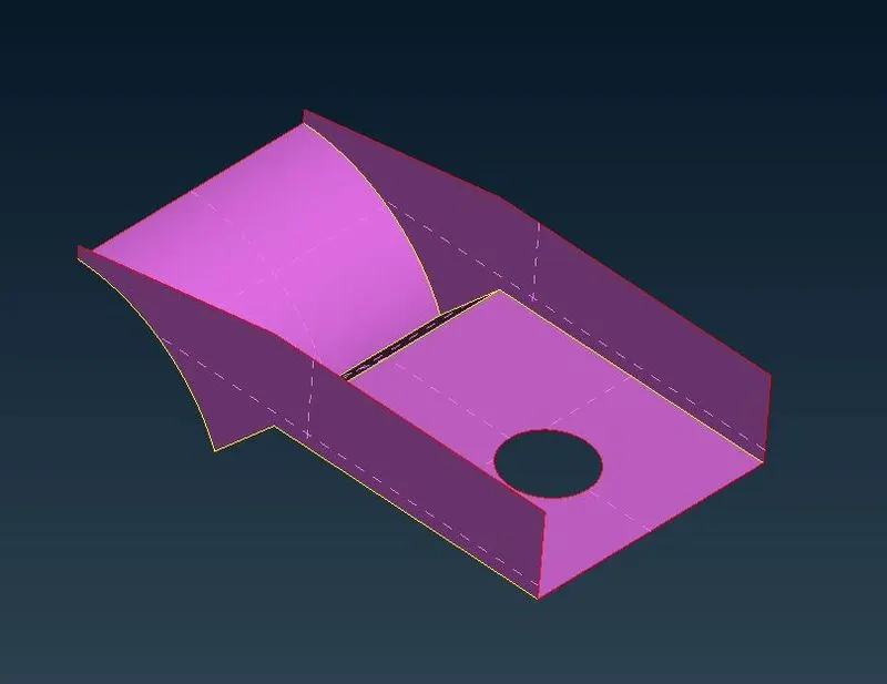
Before going to middle surface extraction, we have to check orientation of faces for CAD model. In order to change orientation, we can use function TOPO---->Faces---->Orient. Where, yellow color shows negative and grey color shows positive direction.
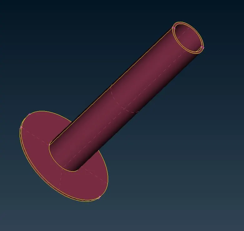
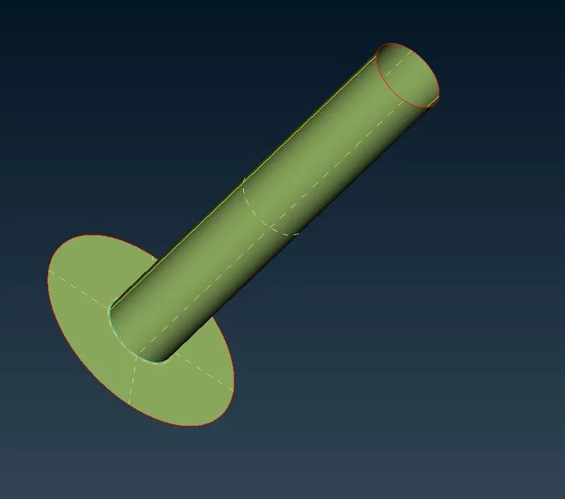
This function sets a uniform orientation to all visible faces according to the orientation of majority of the faces. So, we will extract mid surface for components having thickness uniform and less than 5mm. Once mid surface is extracted, it will look like as shown in picture below.
 |
 |
| shock side support | shock side support |
 |
 |
| shock absorber | shock absorber |
Figure 5: MID surface extraction
3. Mesh Parameters and quality criteria
3.1 Mesh Parameters
Before proceed to meshing, we have to assign different mesh parameters such as average Target length, minimum and maximum target length. And we have to keep element type is “Mixed”. According to these parameters our mesh model will get discretize.
3.1.1 Mesh parameters for uniform thickness components
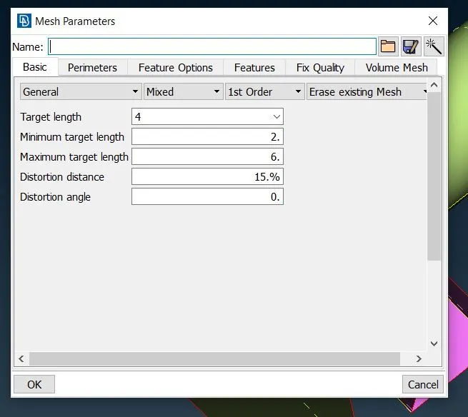
Figure 6: Mesh parameters for uniform thickness components
3.1.2 Mesh parameters for Tyre and Rim
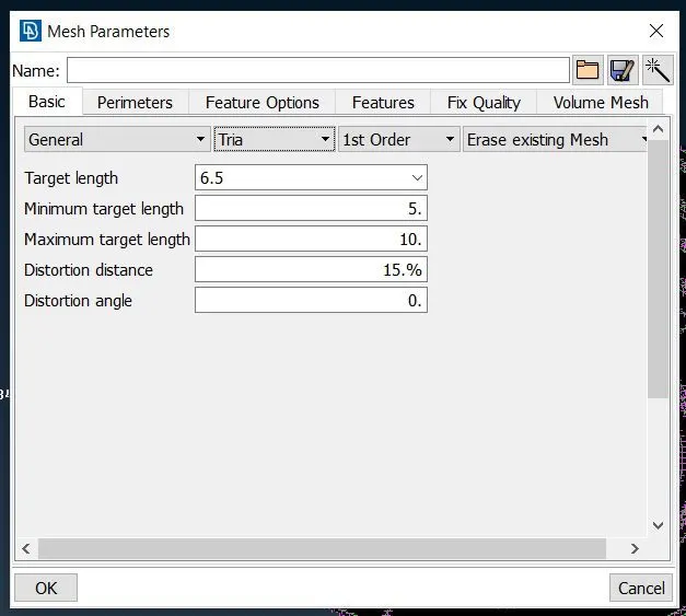
Figure 7: Mesh parameters for Tyre and Rim
3.1.3 Mesh parameters for non-uniform thickness components other than Tyre & Rim
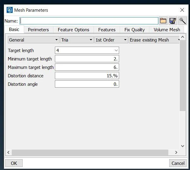
Figure 8: Mesh parameters for non-uniform thickness components other than Tyre & Rim
3.2 Quality criteria
After assigning mesh parameters we have to assign Quality criteria presentation parameters. Quality criteria helps to make understand whether our finite element model will fail or not.
3.2.1 Quality criteria parameters for uniform thickness components
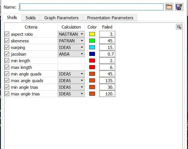
Figure 9: Quality criteria parameters for uniform thickness components
3.1.2 Quality criteria parameters parameters for Tyre and Rim
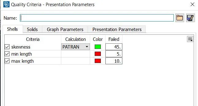
Figure 10: Quality criteria parameters parameters for Tyre and Rim
3.2.3 Quality criteria parameters for non-uniform thickness components other than Tyre & Rim
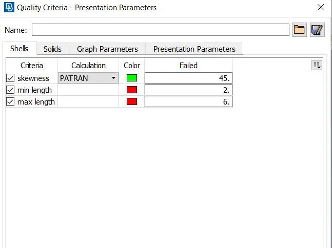
Figure 11: Quality criteria parameters for non-uniform thickness components other than Tyre & Rim
3.2.4 Quality criteria for volume meshing of all non-uniform thickness components
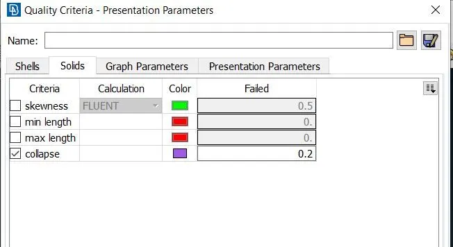
Figure 12: Quality criteria for volume meshing of all non-uniform thickness components
4. Discretization of a component
A mesh is a network that is formed of cells and points. A meshing is the process of subdividing the structure from infinite number of points to the finite number of node and elements. This process is also known as discretization.
And we have to maintain the distance between two nodes equal to the average target length i.e. 4mm. This can be done by following certain steps i.e. MESH---->Perimeters---->Length for both Perimeters and Macros.
Before meshing we have to check topology cleanup requirement of components in model.
In ANSA, we have variety of options to perform meshing. Now, we will use “BEST” or “SPOT” option for meshing to generate FE elements on each and every surface of model. We also use batch mesh manager to generate automatic mesh by creating batch-mesh sessions.
During meshing we have to take care of quality criteria. Because on click of meshing option, it will generate improper meshing. So we have to improve meshing in order to satisfy the quality criteria.
We can use defeaturing to avoid element failing due to quality criteria. Once meshing is done on instrumental panel, model will look like as shown in picture below:
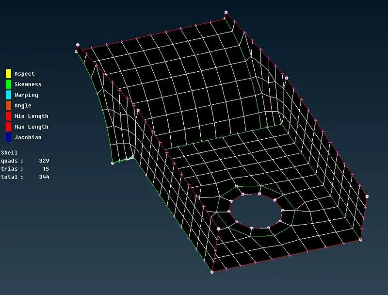
4.1 To perform Shell mesh on middle surface
By using best or spot option with element type mixed, we will perform shell mesh as shown in picture below.
 |
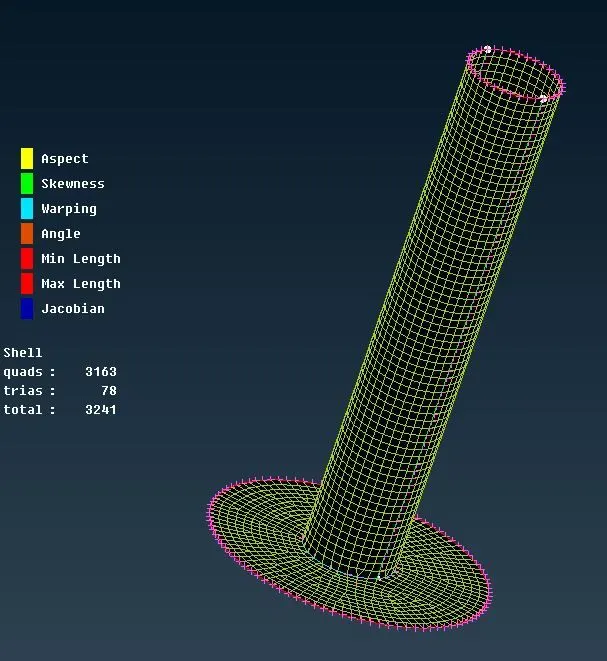 |
| Figure 13: Shell mesh on shock side support | Figure 14: Shell mesh on shock absorber |
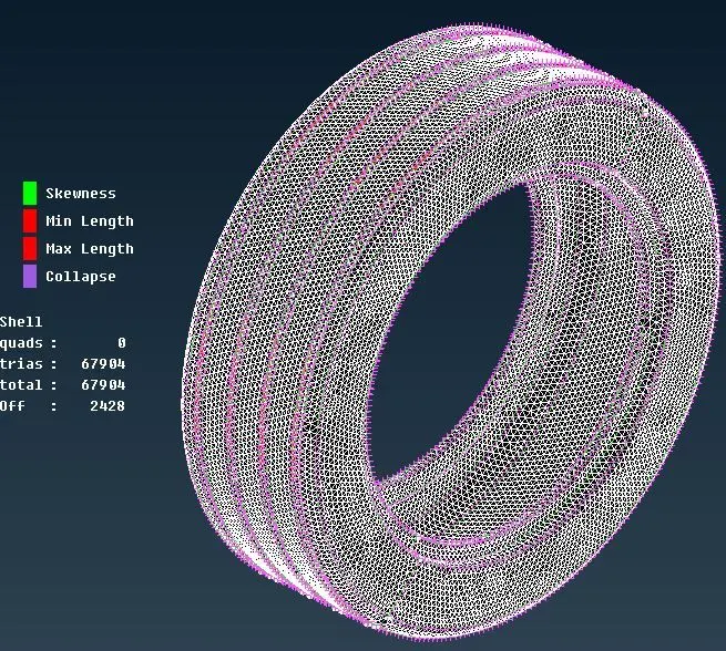
4.2 To perform shell mesh on surface
To generate the tetrahedral mesh, we will use element type i.e. tria only. In order to perform meshing we will use different options such as Best, spot and batch meshing manager to generate meshing on the surface of solid component.
 |
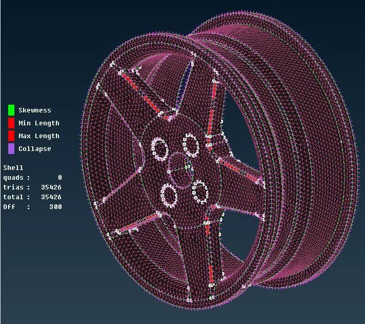 |
| Figure 15: Shell mesh on Tyre | Figure 16: Shell mesh on Rim |
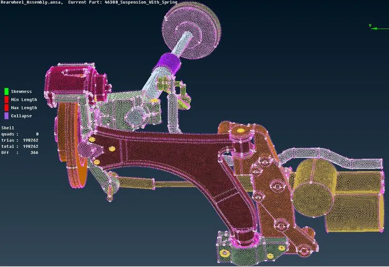 |
| Figure 17: Shell mesh on other solid components |
From above pictures we can see, there are some few off elements are presented in the model due to minimum length or due to intersection of neighboring nodes. These off elements can be ignore because these features are important for analysis of model.
4.3 CONTROL VOLUME
Before proceeding to volume meshing. We have to assign volume for the geometry in the option list as shown in picture below. While doing 2D meshing, we have to make sure there should be no opening.
For 3D meshing, we will use element type Tetra rapid and Tetra FEM.
To create this list, in “Volume Mesh” module we have to select “Manual” option in defines under “VOLUMES” and have to use box selection for selecting certain component.

Figure 18: Control volume list
4.4 TETRAHEDRAL MESHING
To perform tetrahedral meshing, we will use different algorithm type i.e. Tetra FEM and Tetra rapid to generate meshing in interior of volume as shown in picture below.
Also we have to make sure, there should be no kinks and dips on the surface of components. If we get any collapse issues, we have to rectify those elements by moving nodes manually. Some of the methods that can help for improving the quality of elements are as follow:
- Manual adjustment
- Drag node
- Auto quality improvement
Once volumetric mesh is done, it will look like as shown in picture below. So, we have no TET collapse issues in this component.
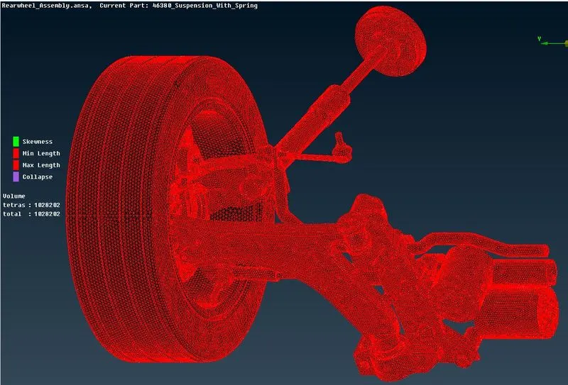
Figure 19: Tetrahedral meshing
Once volumetric mesh is done, the status of mesh is change from unmeshed to meshed as shown in picture below.
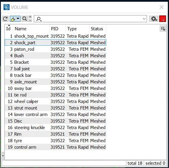
Figure 20: Control volume list
5. To represent a spring with 1D bar element
We have to represent a solid damper spring with 1D bar element. Solid spring is shown in picture below.
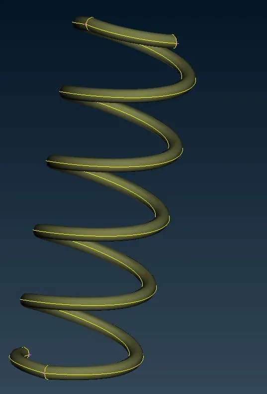
Figure 21: To represent a spring with 1D bar element
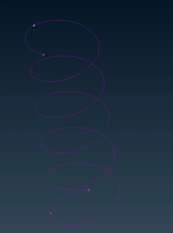
To represent the CBAR element, we have to create a middle curve at neutral axis by using middle curve option which is available under
TOPO---->Curve---->Middle
Then we will select the connect multi option and join the curve in to a single curve.
 |
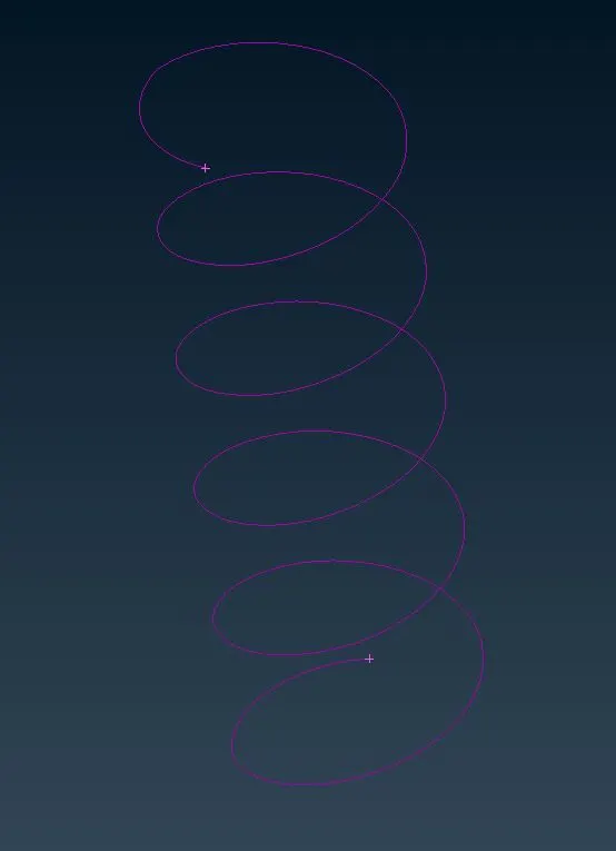 |
Figure 22: To represent a spring with 1D bar element
Now we have to create a COG point for the curve to define the orientation. Then we have to select CBAR element which is available under
NASTRAN DECK---->ELEMENTs---->CBAR
Then in element definition parameters we have to check orientation with node and have to change the selection to the curve box. Then we have to select the curve and give middle mouse click. After then we have to select orientation node i.e. COG point and then middle mouse click for confirmation.
Then need to specify element length i.e. 3mm. Do middle mouse click and then create new PID for damper spring. To assign appropriate radius press (Shift+?) in A section. Then assign value of radius i.e. 5mm. It will automatically calculate the cross sectional area and moment of inertia. After that 1D bar element will be created as shown in picture below.
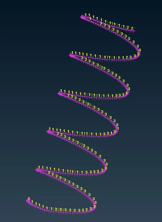
Figure 23: To represent a spring with 1D bar element
In order to see the representation of 1D bar element as 3D solid. Check the Line element cross-section with draw mode as solid in presentation parameters. Then click apply and ok. Now we can see 1D bar element as a solid element as shown in picture below.
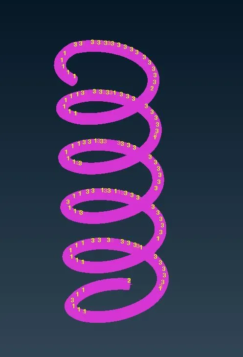
Figure 24: To represent a spring with 1D bar element
6. CONNECTIONS
There are number of connections available. So we will use some of them as follows.
6.1 Rigid Body Element (RBE2):
RBE2 element makes rigid connection and prevents translation and rotational movement in x, y and z axis. We have two type of RBE2 connections to use i.e. RBE2 many node and two node RBE2.
In order to create RBE2 Connection, we have to follow NASTRAN Deck---->ELEMENTs---->RBE2
We will create RBE2 element connection using two methods i.e. Cluster method and two node RBE2.
6.1.1 RBE2 Many Nodes
This type of connections is created between two or more holes using the command as discussed earlier.
First of all, we have to select slave nodes (nodes which are on the perimeter of holes) slave nodes are dependent nodes. Then by clicking middle mouse button master note will select automatically which is independent node. And then RBE2 cluster will form. This method is having multiple number of dependent nodes and one independent node. After assigning this method, connection will look like as shown in picture below
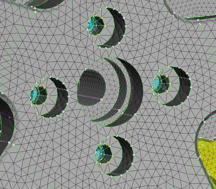
Figure 25: RBE2 Many Nodes
6.1.2 Two nodes RBE2
To make a hinge type of connection, where we need rotating motion either along any of direction. First we have to create many nodes RBE2 on two rigid components. Now by using RBE 2 two node method, rotating link will create between master node of cluster RBE2. As we can observe from global axis, lower control arm has to move along x-axis. So, we will constrain all degree of freedom except rotational movement about x-axis. This constraining is possible by assigning 12356 in CM parameter as shown in picture below. Now lower control arm is free to move around x-axis.
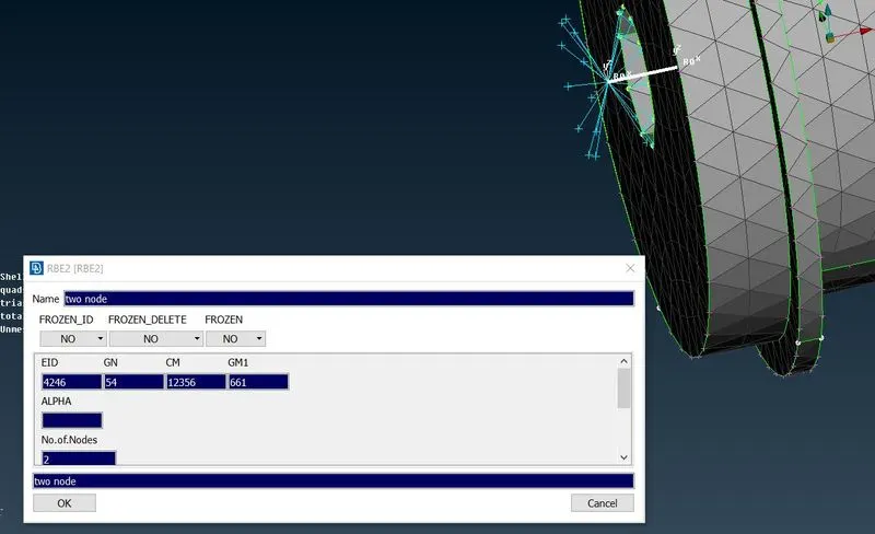
Figure 26: Two nodes RBE2
6.2 Seam weld connection
Seam weld connection is also used to connect two mating parts. Generally, we use two types of seam weld connection i.e. overlap shell and Y-joint shell. Overlap shell connection is used when we have to connect two parts which are parallel to each other. And Y-joint shell is used when we have to connect two parts which are perpendicular to each other.
Here, in this case we will use overlap shell weld connection. Steps to create connection are as follow:
Mesh module ----> Perimeter----> Feat2curv. This command defines 3D curve from the selected feature line of mesh.
Now we have to convert the curve into seam line. Then using connection manager, we have to select overlap shell in FE representation type. Now overlap shell weld connection is established between parallel mating parts by selecting appropriate sheets in P1 and P2 as shown in picture below.
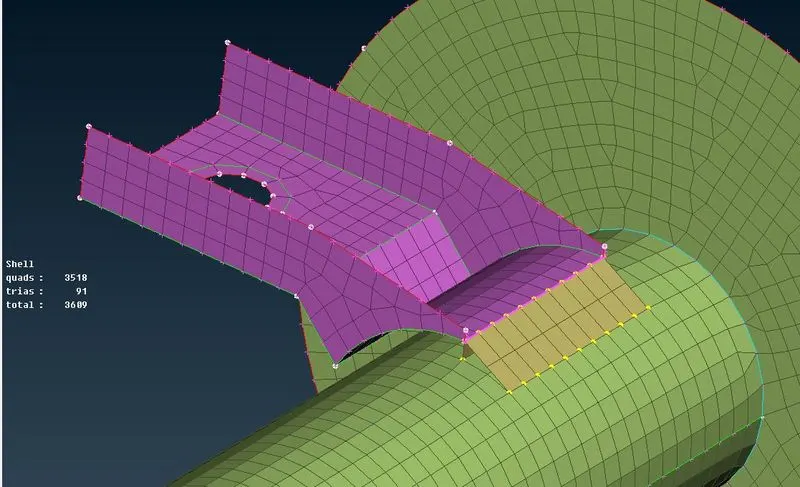
Figure 27: Seam weld connection
7. Symmetry operation
This function creates symmetric entities. At the drop down menu there are the options to use the default symmetry plane or the current working plane or select from the screen the symmetrical point, axis or plane that is going to be used. We will use mirror 3 points plane to reflect the half-finished model to the other side as shown in picture below.
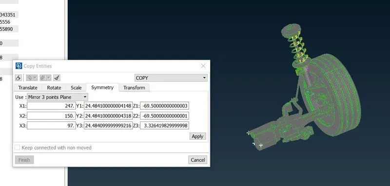
Figure 28: Symmetry operation
Learning Outcomes
- Able to fix geometric errors.
- Extracting mid surface.
- Shell mesh using quads and tria elements.
- Volume mesh using Tetra rapid and Tetra FEM.
- Creating connections using Nastran deck.
- To use symmetry operation.
CONCLUSION
Preprocessing is done successfully on CAD model of rear wheel suspension model such as geometry check, middle surface extraction, shell meshing with mixed and volume mesh with Tria elements. Defining volumes for volumetric meshing, represent spring as 1D bar element. then deploying proper connection which is followed by symmetry option.
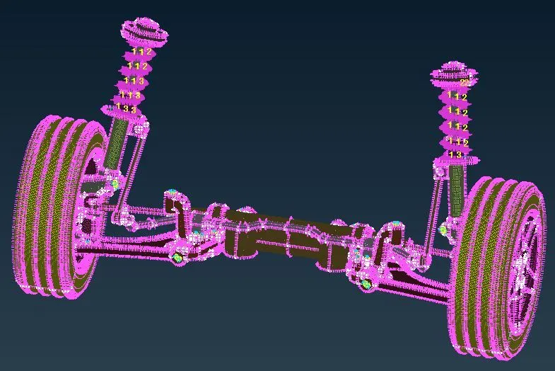
Figure 29: Rear wheel suspension model