Preparing Schedule & Cost Estimation for a building using REVIT
1a. Aim: To list the short cut keys which will be used during the creation of the building model unit in the rivet.
- In the process of the creation of the building unit many operations is to be used and for the time saving and to get the quick result short keys are used to get the instant change in the building model.
- The short cut keys may be used in all the plans and elevations of the model and it will give the instant result with out any deviation in the model creation.
- The model can also be created from the icons in the ribbon tab but moreover we can also use this short cut keys to modify the changes in the building model.
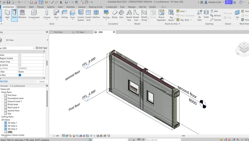
a. Section box:Section box is the tool used to create the 3d view of the particular element in the view for the muitistorey or for any large commercial building there will be the lot of elements in the building model and for suppose if we need to get any particular 3d view of the elemennt separately we can use this section box tool and the short cut key to use this section box tool is 'BX'.
Procedure:
- Click on the open option and select the model in the file menu click on OK then the file with the model formed is opened.
- Now click on the 3d view in the project browser, now the 3d view of the building is opened.
- Now selct the element it may be wall,door,window,floor,slab,column or any other structural or furniture tool and enter 'BX' and press enter the section box with the sellected elment will be created and it will be useful for the designer to enahnce the details of the element separately.
- The result of the section box tool is shown below.
b. To create the similar doors and windows
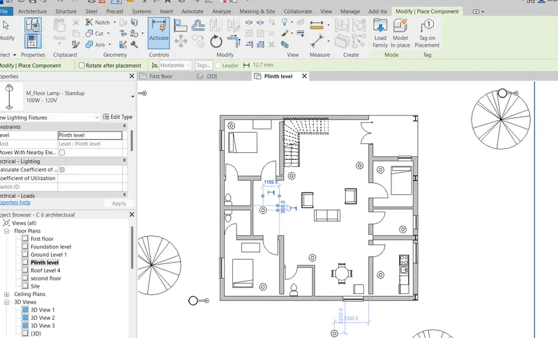
Create similar (CS):It is the tool used to create the similar doors,windows or any other furniture items.In a building there will be more number of elements like doors,windows,furniture items.The elements in the building are inserted from the ribbon bar in the rivet while the doors and windows are inserted from their respective families and it may take long time to create the element from the families.In the buildings the some of the elements may undergo same size and specifications and those elements are created using the create similar shortcut key.
Procedure:
- Click on the open option and select the model in the file menu click on OK then the file with the model formed is opened.
- Now click on the floor paln in the project browser, now the floor plan of the building is opened.
- Now select the element it may be wall,door,window,floor,slab,column or any other structural or furniture tool and enter 'CS' and press enter then the similar element which we selected is created and place the similar element in the place where it is needed and it will be useful for the designer to create the similar elemets very quickly.
- The result of the created similar tool is shown below.
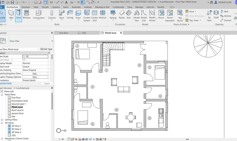
c.To reduce the thickness of the lines in the plan view:In the model creation for the plan view the lines of the walls or columns or beams may undergo certain thickness and due to the thickness the model may look clumsy if there are more number items are specified in the model so the thickness is to be modified if needed and this can be done by using the shortcut key Thin lines(TL).
Procedure:
- Click on the open option and select the model in the file menu click on OK then the file with the model formed is opened.
- Now click on the floor plan view in the project browser then the floor plan is opened.
- The model may contain various walls and the wall may undergo certain thickness,the thickness is modified by using the Thin lines option.select the wall in the floor plan and now enter the 'TL' and then the thckenss of the wall is modified if the thickness is more then it will be reduced and if the thickness is less then it will be increased.
- The result for the Thin lines is obtained as shown below.
d. Over ride to a floor (VG):
- It is the projection or the surface created for the floor by using the visibility garphics icon in thhe rivet the surface created will differentiate the floor from the plan of the building and it is better understand quickly about the floor of the building.
Procedure:
- Click on the open option and select the model in the file menu click on OK then the file with the model formed is opened.
- Now click on the floor plan view in the project browser then the floor plan is opened.
- Select the floor in the model and enetr the VG then the visibility graphics is opened and selct the floor on the VG tool bar and change the overrides to the desired content and press enter then the floor over rides are updated and ithe floor is get differentiated from the plan for better understanding.
- The result for the overrides to the floor is as shown below.
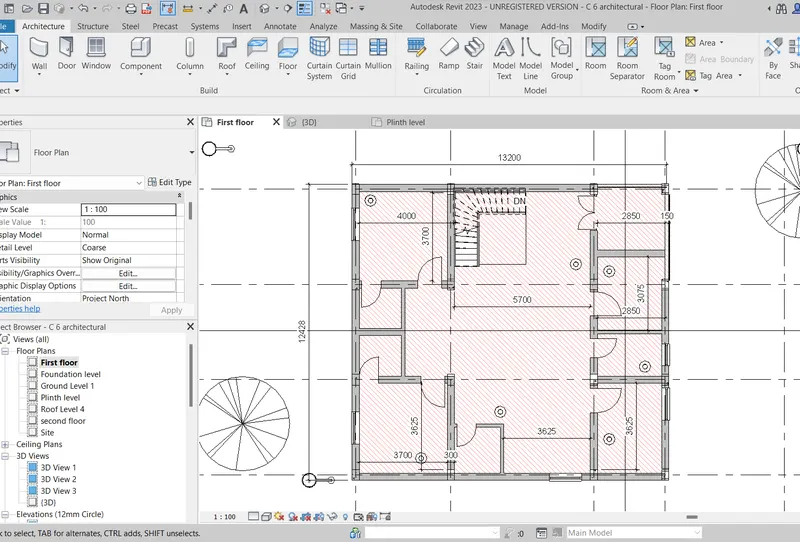
e.Visibility range (VR):It is the level at which the plan of the building model is viewed from the top of the building and it is useful to prepare the plan of the buildings from the various levels.
Procedure:
- Click on the open option and select the model in the file menu click on OK then the file with the model formed is opened.
- Now click on the floor plan view in the project browser then the floor plan is opened.
- Now eneter the VR and change the parameters of the primary range the cut plane will be the plane where the plan is cut and the view is prepared and the view range is editted where the plane can be viewed from the above distance and the bottom plane can also be changed to which the plan can be plotted and the offset distance also be editted at which the plan of the building is viewed from the offset distance.
- The result for the visibility range for the floor is as shown below.
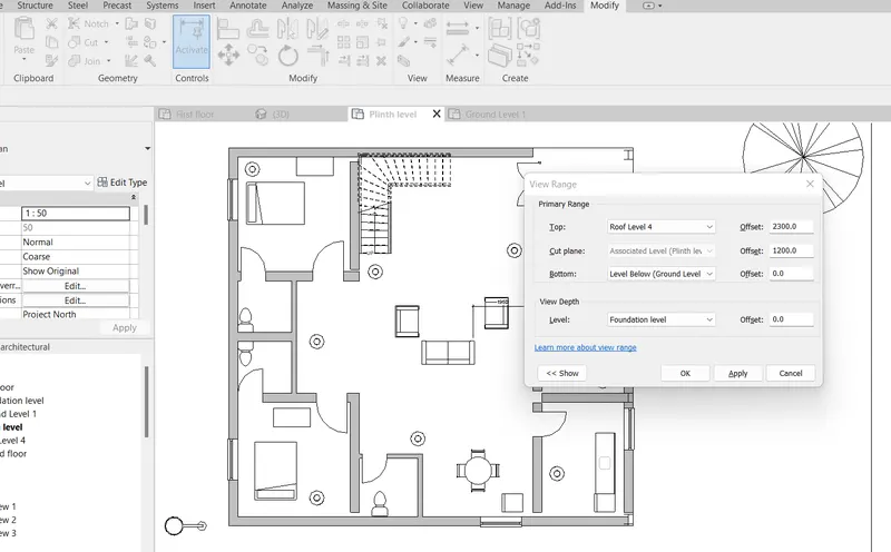
f. To select the previously selected items:It is the tool by which can get the selcted items back if they are free from the selction .
Procedure:
- Click on the open option and select the model in the file menu click on OK then the file with the model formed is opened.
- Now click on the floor plan view in the project browser then the floor plan is opened.
- In many situation we have to select the various items for the modification at that time by selected items may got free from the selection due to mishandling of the keys inthat situation we can get back the selected items by using the short cut key Ctrl+< (left arrow key) by using this key we can get back the selected items.
- The result for the previously selected for the floor is as shown below.
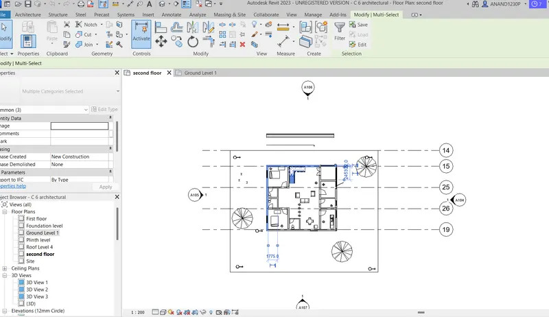
g.Annotations:It is the tool bar in the ribbon where we can find the various icons regarding the dimensions,corordinate,tags, beam annotations, text and sell check etc.This annotation tool bar is generally used to give the dimensions for the plan of the building model and by these we can get to know the size of the rooms or the building lay out and these are the very important and basic tool in the annotation tool bar. The short cut key used for the dimensions is 'DI'.
Procedure:
- Click on the open option and select the model in the file menu click on OK then the file with the model formed is opened.
- Now click on the floor plan view in the project browser then the floor plan is opened.
- Now click on the annotate icon in the ribbon and slect the dimensions option and the dimensions are placed to the rooms whether it is interior or exterior or we can use the short cut key DI by entering the DI we can assign the dimension to the rooms wher the dimension is required.
- The dimesnsions selected may be linear or align dimensions based on the plan in genral align dimensions are used for the inclined aurfaces like the stair cases or the for the walls which are at the angle other than the 90 degrees.
- The result for the annotation for the floor is as shown below.
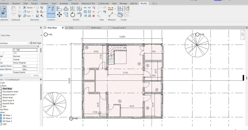
h.To bring the model elements in a line : It is tool which is used to get align the elements in a line where we required and the short cut key to align the elements in a line is 'AL'.
- Click on the open option and select the model in the file menu click on OK then the file with the model formed is opened.
- Now click on the floor plan view in the project browser then the floor plan is opened.
- In a building some of the elemnets or the furniture items are to be aligned with the walls and so in that case we can make the objects aligned with the walls or any other surface.
- select the object to be aligned and enter the short cut key 'AL' and again select the object to be aligned and click on the objected for which the objects are alinged then the two elements are aligned with each other.
- The result for the align the building elements is as shown below.
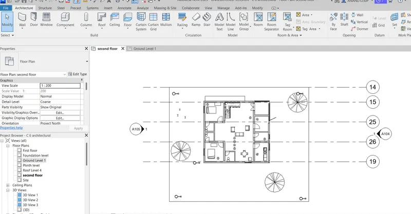
i.Rotate(Ro):Rotate is the icon by which we can rotate the objects like furniture or building elements like walls,columns, beams etc at a particular axis.Rotate option will be useful to arrange the furniture in the rooms to occupy the lesser carpet area.The furniture may occupy more area in rare cases at that case we can use this rotate option and change the arrangement of the furniture to occupy the lesser carpet area.
Procedure:
- Click on the open option and select the model in the file menu click on OK then the file with the model formed is opened.
- Now click on the floor plan view in the project browser then the floor plan is opened.
- Select the furniture or any other building element in the model and enter RO then the the rotate process for the element is started and select the base point at which the building element is about to rotate and rotate the building element to the desired angle then the element is rotated by the particular angle.
- The result for the rotate option for the building element is as shown below.
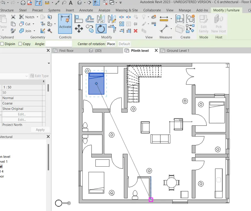
j.Move(MV):In the building model creation some times the furniture or the building elements have to be moved in the process of the design.then the building elemnts can be moved by shortcut key MV and the elemnts are moved according to the requirements of the inmates or according to the design requirements.
Procedure:
- Click on the open option and select the model in the file menu click on OK then the file with the model formed is opened.
- Now click on the floor plan view in the project browser then the floor plan is opened.
- Select the furniture or any other building element in the model and enter RO then the the rotate process for the element is started and select the base point at which the building element is about to rotate and rotate the building element to the desired angle then the element is rotated by the particular angle.
- The result for the rotate option for the building element is as shown below.
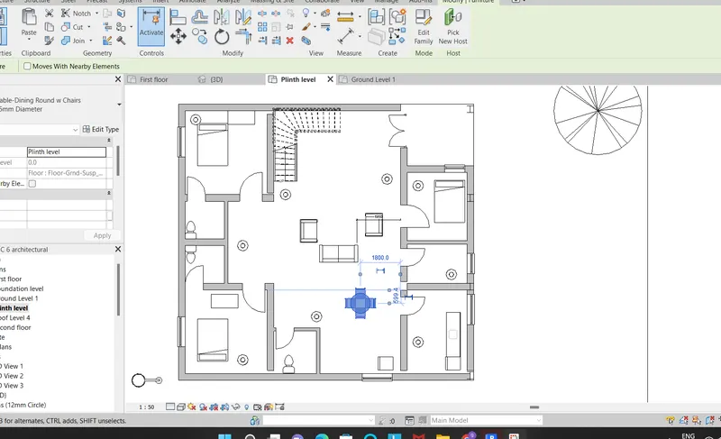
k.Copy (co):The building elements with the similar properties are sometimes need to be copied to the place where there is the requirement of two or more elements in the building.To reduce the time for the creation of the building elements we can use the short cut key copy CO to copy the elements and we can place the items where we needed.
Procedure:
- Click on the open option and select the model in the file menu click on OK then the file with the model formed is opened.
- Now click on the floor plan view in the project browser then the floor plan is opened.
- Select the furniture or any other building element in the model and enter CO then the the copying process of the element is started and select the base point at which the building element is about to copied and click on the place where we need the building element to the desired angle then the element is copied by the particular angle.
- The result for the copy option for the building element is as shown below.
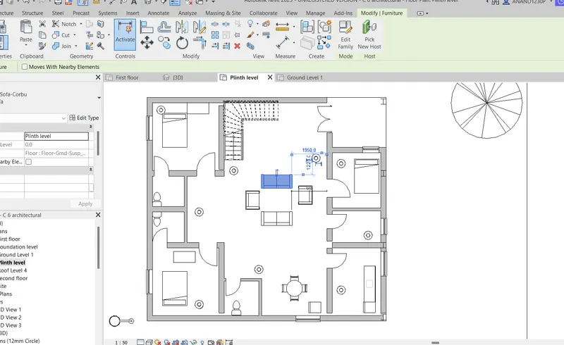
l. Mirror(mm): It is the option where we need to place the building element or any other furniture with the same size and shape but opposite to each other.It may take time to create the building element with the same size and specification but with the opposite direction we mirror the elemnt to reduce the time and to get placed in the better option.The short cut key for the mirror is 'mm'.
Procedure:
- Click on the open option and select the model in the file menu click on OK then the file with the model formed is opened.
- Now click on the floor plan view in the project browser then the floor plan is opened.
- Select the furniture or any other building element in the model and enter mm then the mirror process of the element is started and select the axis if there is any or select the option from the ribbon so that the axis is created and the building element is mirrored by that axis.
- The result for the mirror option for the building element is as shown below.
M. Array AR:It is the tool where we can copy the item and place the same item in required nos that is more than two with the desired angle.In the building design we need to place the same items at regular intervals so we can use the array option to place the items at regular intervals and the short cut key for the array option is AR.
Procedure:
- Click on the open option and select the model in the file menu click on OK then the file with the model formed is opened.
- Now click on the floor plan view in the project browser then the floor plan is opened.
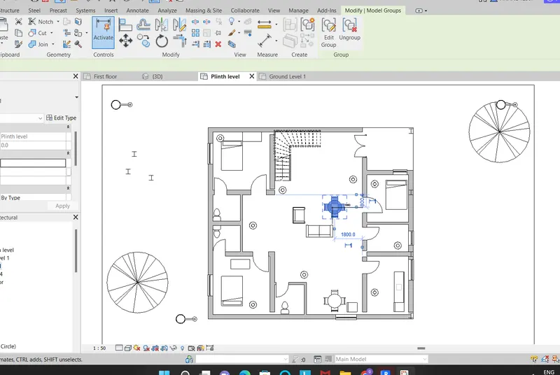
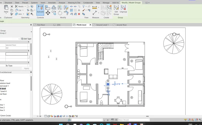
- Select the furniture or any other building element in the model and enter AR then the edit the number of items we need to copy using the array option and the distance between the items are also changed and then the items are placed ta the regular interval.
- Ingeneral the array option is used to place th stairs or lights for the ceiling or for the columns in the rectangular grid.
- The result for the array option for the building element is as shown below.
2a. Aim: To create the schedule for the various elements of the building using the rivet.
- Schedule defines the list of the specific building elements with various size and specifaction in the tabular form.
- The schedule gives the information about the items size,crossection,type and cost and also the schedule gives the information about the various parameters which we give input.
- Schedule helps to know about the building elements for the skilled and unskilled persons and also the schedule gives the information about quantity of the elements also.
Procedure :
Wall schedule
- Click on the open option and select the model in the file menu click on OK then the file with the model formed is opened.
- Now click on the floor plan view in the project browser then the floor plan is opened.
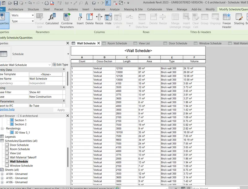
- Now select the view icon in the ribbon and select the schedule option and enter the category which we need to create the schedule i.e wall schedule and enter the categories count,crossection,length,area, type,volume etc and also other parameters which we needed and click ok then the wall schedule is formed and it is displayed.
- The categories in the schedule may insert or delete according to the client requirement.
- The result of the wall schedule formed is shown below.
Wall schedule:
Door schedule
- Click on the open option and select the model in the file menu click on OK then the file with the model formed is opened.
- Now click on the floor plan view in the project browser then the floor plan is opened.
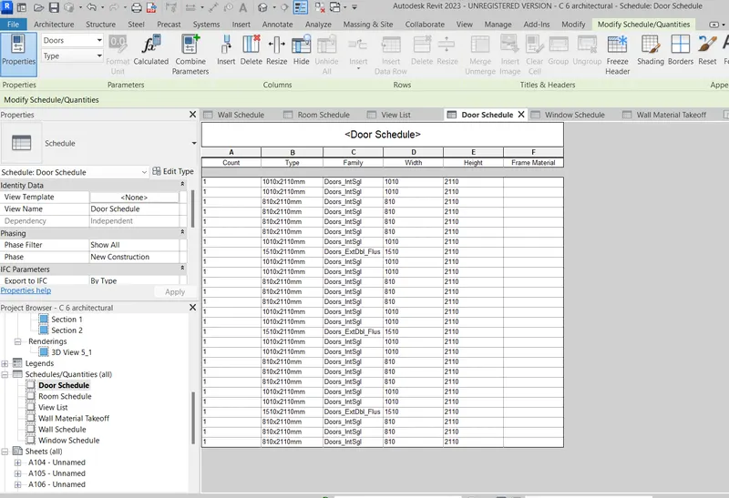
- Now select the view icon in the ribbon and select the schedule option and enter the category which we need to create the schedule i.e Door schedule and enter the categories count,type ,width,frame height frame material etc and also other parameters which we needed and click ok then the wall schedule is formed and it is displayed.
- The categories in the schedule may insert or delete according to the client requirement.
- The result of the door schedule formed is shown below.
Door schedule:
Window schedule
- Click on the open option and select the model in the file menu click on OK then the file with the model formed is opened.
- Now click on the floor plan view in the project browser then the floor plan is opened.
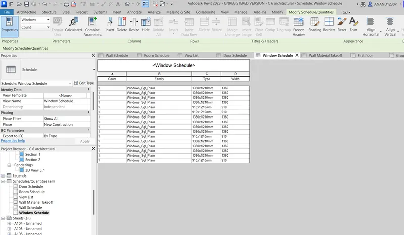
- Now select the view icon in the ribbon and select the schedule option and enter the category which we need to create the schedule i.e window schedule and enter the categories count,type, family,width,frame height frame material etc and also other parameters which we needed and click ok then the wall schedule is formed and it is displayed.
- The categories in the schedule may insert or delete according to the client requirement.
- The result of the window schedule formed is shown below.
Window schedule:
Material schedule
- Click on the open option and select the model in the file menu click on OK then the file with the model formed is opened.
- Now click on the floor plan view in the project browser then the floor plan is opened.
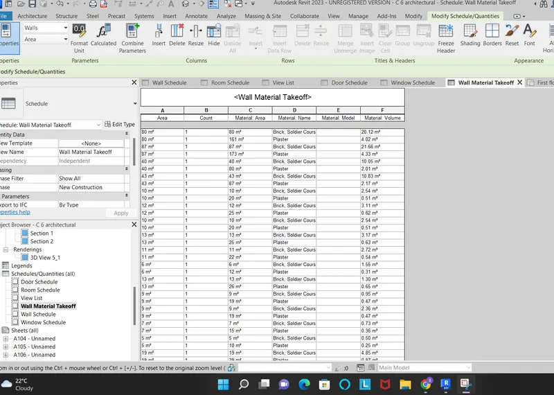
- Now select the view icon in the ribbon and select the material take off option and enter the category which we need to create the schedule i.e wall material or window material or column or beam material or floor material and enter the categories count,type, family,width,frame height, frame material etc and also other parameters which we needed and click ok then the material schedule is formed and it is displayed.
- The categories in the schedule may insert or delete according to the client requirement.
- The result of the material schedule formed is shown below.
Material schedule:
3a. Aim: To create the schedule for the various elements of the building using the rivet.
- Schedule defines the list of the specific building elements with various size and specifaction in the tabular form.
- The schedule gives the information about the items size,crossection,type and cost and also the schedule gives the information about the various parameters which we give input.
- Schedule helps to know about the building elements for the skilled and unskilled persons and also the schedule gives the information about quantity of the elements also.
Procedure :
Wall schedule
- Click on the open option and select the model in the file menu click on OK then the file with the model formed is opened.
- Now click on the floor plan view in the project browser then the floor plan is opened.
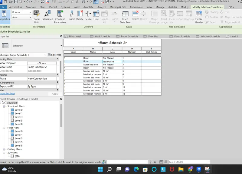
- Now select the view icon in the ribbon and select the schedule option and enter the category which we need to create the schedule i.e room schedule and enter the categories count,area,name of the room etc and also other parameters which we needed and click ok then the room schedule is formed and it is displayed.
- The categories in the schedule may insert or delete according to the client requirement.
- The result of the room schedule formed is shown below.
Room schedule:
4a. Aim: To find the cost of the building element by creating the material schedule for the various elements of the building using the rivet.
- The cost of the building element is inserted in the properties browser and then the material schedule is formed to get to know the cost and estimation for the building the building may be executed in various stages and for the each stage the material per cubic feet is calculated and the material cost is entered in the properties browser.
- The material schedule is prepared by inserting the beam various categories like cost,count,material name etc.
Procedure:
- Click on the open option and select the model in the file menu click on OK then the file with the model formed is opened.
- Now click on the floor plan view in the project browser then the floor plan is opened.
- Now selct the wall or any other building material and edit the cost in the properties browser and click ok, then the cost of teh material is saved in the project and use ful for the cost estimation.
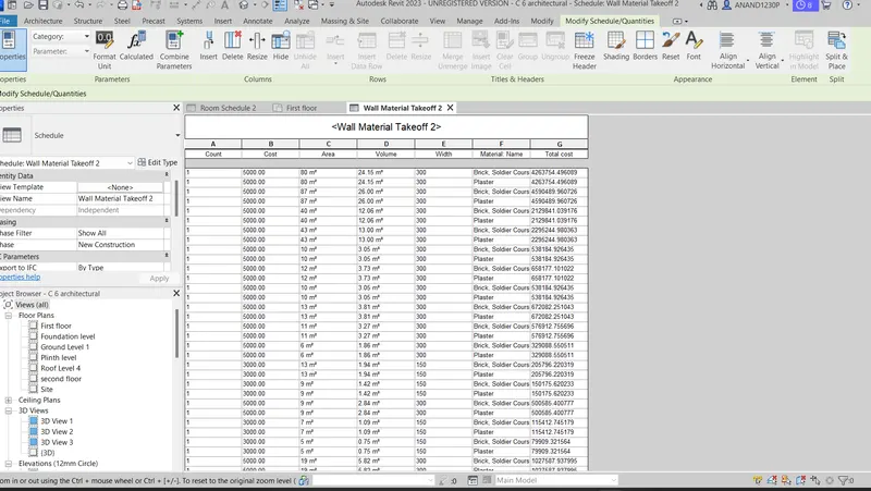
- Now select the view icon in the ribbon and select the material take off option and enter the category which we need to create the schedule i.e wall material or window material or column or beam material or floor material and enter the categories count,type, family,width,frame height, frame material etc and also other parameters which we needed and click ok then the material schedule is formed and it is displayed.
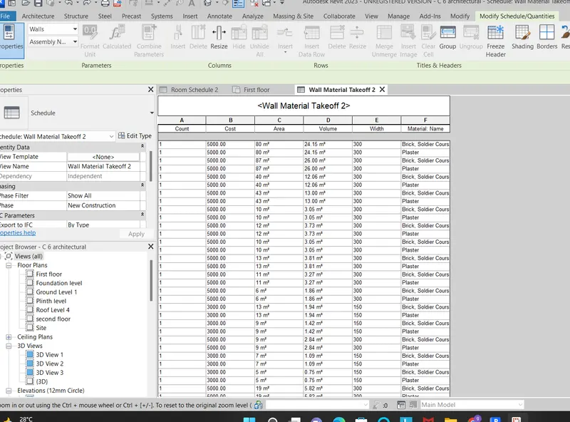
- The material schedule is formed with the individual unit costs and now enter the dummy category in the material schedule and insert the formula for the total cost of the mterial then the total coset of the material is updated and it gives total cost for the particular building element.
- The total cost of the materials of th building formed is shown below.
5a. Aim: To create the flow chart for the various progrmmane in the dynamo of the rivet.
- The flow chart is the step by step by step procedure for the programme to execute in a clean and transparent manner with out any undulations.
- Every programme or any other project should follow the order of the execution process to avoid the inconvinience and also the hazrds to avoid those problems we need to create the flow chart of the programme forthe better execution with out any deviation.
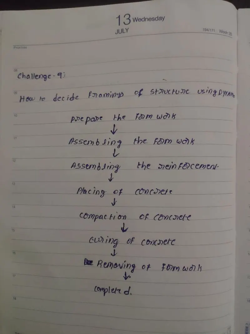
a.To decide the framing of the structure using the dynamo.
- To finalise the framing of the structure we need to follow the various steps in the dynamo.
- For every structure first we need to prepare the form workto the required size and after the preparation of the form work assembling of the form work is carried and next to it the reinforcement is placed according to the sizesmentioned in the drawing or barbending schedule of the structure.
- After the placing of reinforcement ,concrete is placed with the well designed mix proportionand the concrete is compacted after placing on form work with out anybleeding,float and segregation.
- The structure is to be done curing for the required number of days to attain the strength and after the curing we canremove the form work of the structure.
- For the brief discussion the flow chart is prepared for the above points is shown as below.
b. If there is no water coming from the pipes:
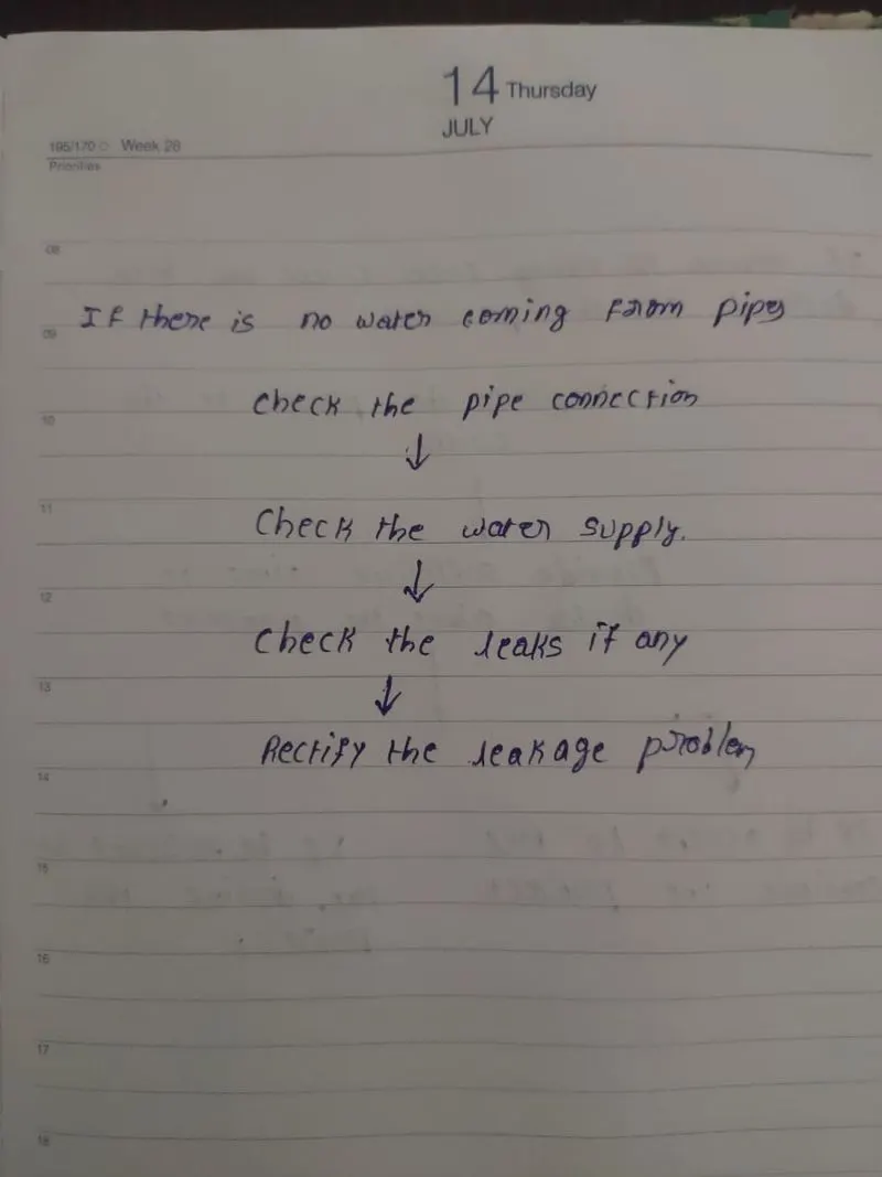
- For the rectification of the pipes to allow the flow in the pipes the following steps to be followed.
- Primarily check the pipe conection and if it s fine then the check the water suply source is able to dischare water or not and after that check the leakages if there any in the line and as well as near the valves of the pipe and the leakages are closed with necessary repair work.
- After the fixing the leakage of the pipes the system is ready and the water is allowed in to the pipes
- For the brief discussion the flow chart is prepared for the above points is shown as below.
c. If request for the money from the client has been declined for the project.
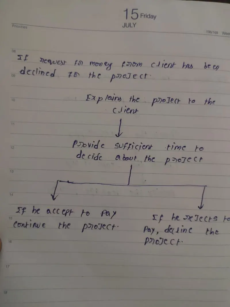
- During the project period some due to the external reasons the money or the funds may get delay to the project and at that time we need to follow steps to request the money from the client.
- Firstly explain the porject to the client about the site condition and the working status of the project and the explanation also includes the hirdance reasons if there any.
- Allow the client to think about the situation of the project by considering the all reasons in to the account.
- If the client accept the pay then continue the project or if he rejects the pay then we can decline the project or else we can rectify the problems which are creating problems.
- For the brief discussion the flow chart is prepared for the above points is shown as below.
6a. Aim: To list out the parameters associated with each model elemnt in the building using the rivet.
- In the building various elements are provided with the various sizes and specifications, the parameters of the elements may tells about the various properties of the element.
- Based on the parameters we can specify the elemnet properties and by changing the parameters of the element the properties of the element can be changed according to the building condition.
- The parameters generally visualised in the properties browser of the rivet.
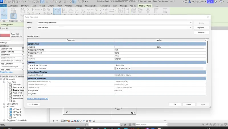
a.Wall
- Wall is one of the building elemnet which is used in the building for the partition of the rooms with various sizes.
- Wall contains various parameters like construction,grahics and analytical properties, material and finishes.
- Ingeneral we use analytical properties and as well as material and finishes to modify the wall in the building model creation.
- The parameters of the wall is shown below.
b. Floor
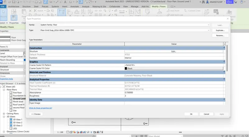
- Floor is one of the building elemnet which is used in the building to provide the smooth and flexible surface to move inside the building.
- Floor contains various parameters like construction,grahics and analytical properties, material and finishes.
- Ingeneral we use analytical properties and as well as material and finishes to modify the floor in the building model creation.
- The parameters of the floor is shown below.
c. Door
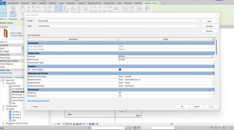
- Door is one of the building elemnet which is used in the building to provide the access of the building into the rooms .
- Doors contains various parameters like construction,grahics and analytical properties, material and finishes.
- Ingeneral we use analytical properties and as well as material and finishes to modify the door in the building model creation.
- The parameters of the door is shown below.
d.Window
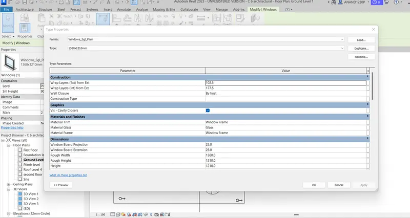
- Window is one of the building elemnet which is used in the building to provide the ventilation and circulation of the heat and air to the building.
- Windows contains various parameters like construction,grahics and analytical properties, material and finishes.
- Ingeneral we use analytical properties and as well as material and finishes to modify the window in the building model creation.
- The parameters of the window is shown below.
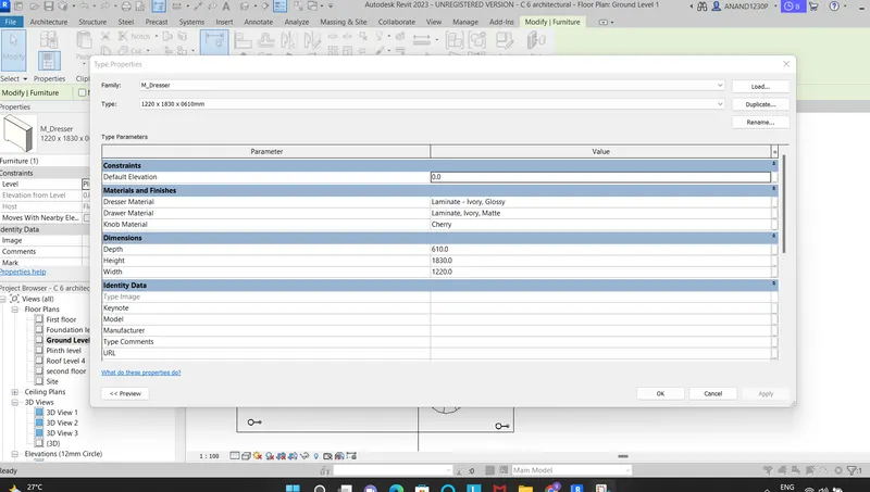
e.Table or dresser:
- Table is one of the furniture elemnet which is used in the building to facilatate the surface to place the various of things which full fill the daily routines like food or working platform etc.
- Table contains various parameters like construction,grahics and analytical properties, material and finishes.
- In general we use analytical properties and as well as material and finishes to modify the table in the building model creation.
- The parameters of the table is shown below.
f.Building:
- It is the structure which is created for the people or the public to have residence in the structure and it protect the inmates from the weather and also it is a ssfe to live with out any problems.
- Building contains various parameters like graphics and identity data and the identity data provides the plan of the various floors.
- The parameters of the building is shown below.