Planetary Gear
AIM:- To design and run the simulation of the Planetary Gear train using SolidWorks.
Objective: -
- To create internal ring gear with the following properties -
Module = 2.5 (ANSI METRIC must be used while selecting Gear train).
Number of teeth = 46
- To create sun gear with the following properties -
Sun Gear
Number of teeth = 14
- Input Speed of the Gear = 200 rpm.
Number of planet gears = 4
The carrier must be designed based on the other components (considering safe design).
- Finally, after the SolidWorks Model, We are going to run a simulation on the following cases,
|
S.No |
Input |
Output |
Fixed |
|
1 |
Sun Gear |
Carrier |
Ring Gear |
|
2 |
Ring Gear |
Carrier |
Sun Gear |
|
3 |
Sun Gear |
Ring Gear |
Carrier |
Input- Rotary Motion given to that part as input.
Output- After motion analysis, the Angular Velocity of that part is plotted as a graph.
Fixed-Make that particular component as a fixed part.
- Note - Gear mates are not to be used.
- Note - The module is the same for all the gears.
Theory:-
The epi-cyclic or planetary train. This is a two-DOF device. Two inputs are needed to obtain a predictable output. In some cases, such as the automotive differential, one input is provided (the driveshaft) and two frictionally coupled outputs are obtained (the two driving wheels). In other applications such as automatic transmissions, aircraft engine to propeller reductions, and in-hub bicycle transmissions, two inputs are provided (one usually being a zero velocity, i.e., a fixed gear), and one controlled output results.
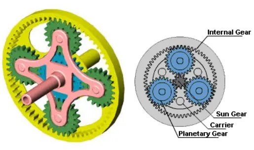
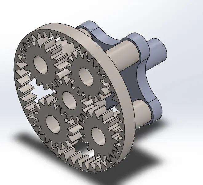
Planetary trains can be used to achieve large speed reductions in a more compact space than a conventional gear train. However, a greater benefit is the ability to readily alter the train value. Because all links are capable of moving, one can alter the train value by holding different gears or carriers. In practice, switching the fixed link is accomplished with brake or clutch mechanisms, thus releasing one link and fixing another. For this reason, planetary gear trains are very common in automotive transmissions. Because the motion can resemble the planets rotating about the sun in our solar system, the term planetary gear train was applied to this system. Expanding on this comparison, the center gear is called the sun. Gears that revolve around the sun are called planets. A carrier holds the planet’s gears in orbit around the sun. Finally, the train is commonly encased in the internal gear termed the ring gear.
Calculations: -
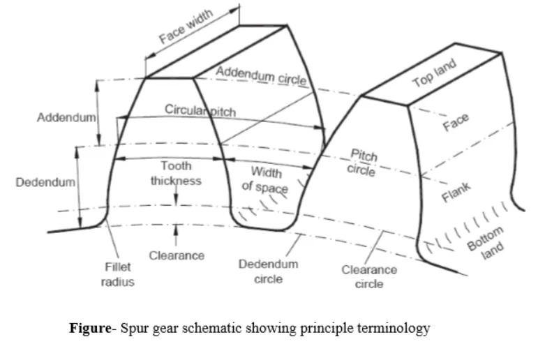
Pitch circle(d):- Its diameter is called the pitch diameter.
d = m. T
Where ;d is the pitch diameter (mm); m is the module (mm), and T is the number of teeth
Module: -
Typically the height of a tooth is about 2.25 times the module. Various modules are illustrated in the figure.
m=(dT)
m=(dT)
v Addendum, (a). This is the radial distance from the pitch circle to the outside of the tooth.
v Dedendum, (b). This is the radial distance from the pitch circle to the bottomland.
Clearance (C) is the amount by which the dedendum in a given gear exceeds the addendum of its mating gear.
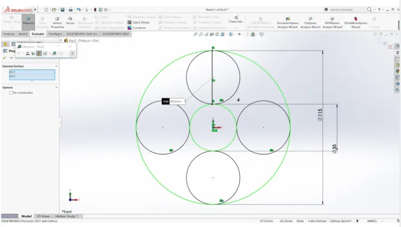
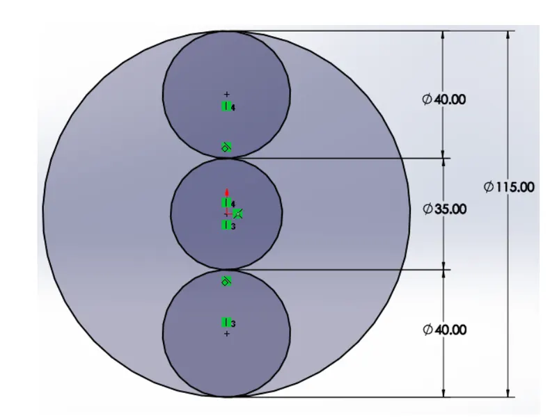
From the geometric orientation of the system, the diameter(pitch) of the planet’s gear can be found as, Since the module is the same for all the gears.
Ø Dr = Ds+2⋅Dp
Ø Dp=40 m and TP = 16.
CAD MODEL (Using SolidWorks) :-
Different components and their 3D representation are as follows:-
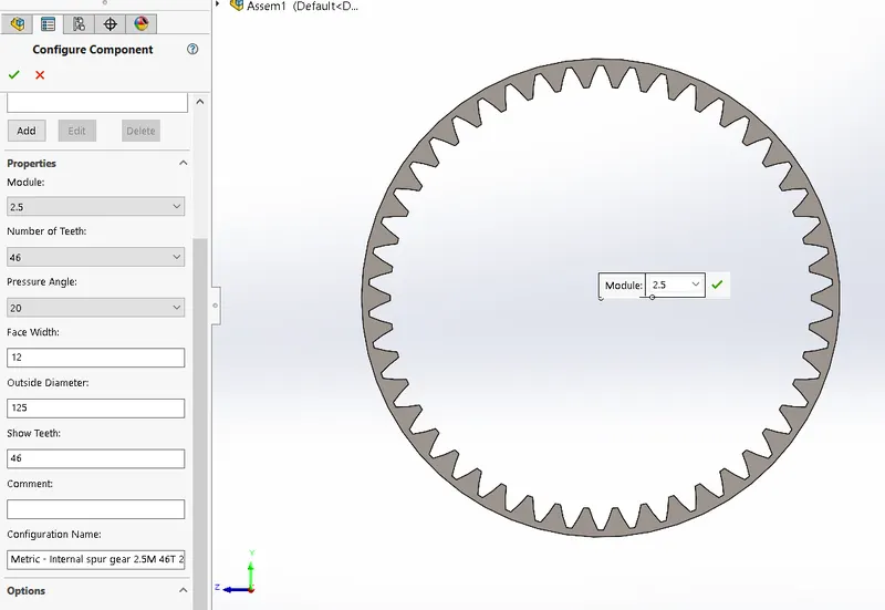
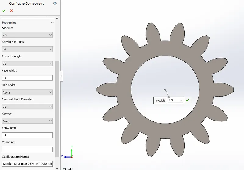
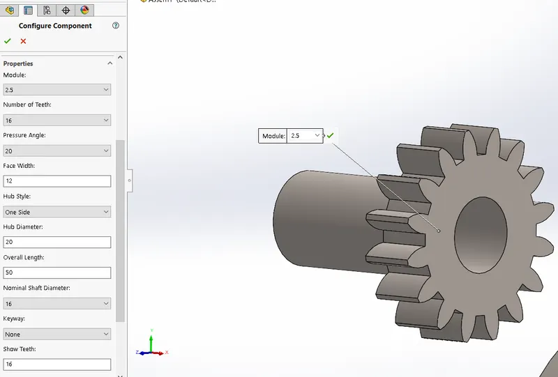
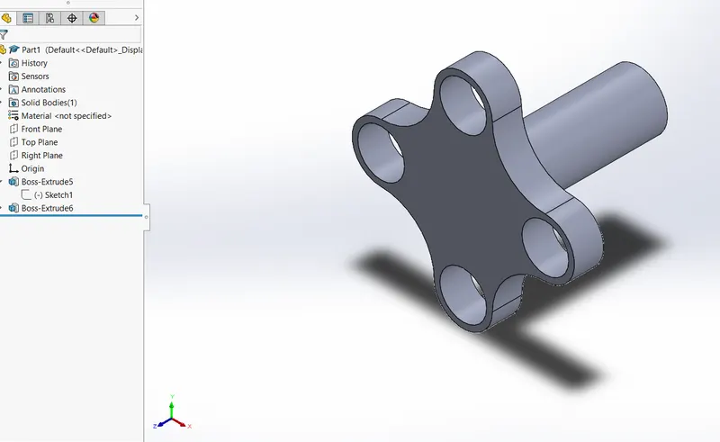
FINAL ASSEMBLY OF THE MODEL
MOTION ANALYSIS AND SIMULATION (in SolidWorks)
Finally, After completing with Zero interference Assembly within the Gear train and carrier, We can initiate our motion analysis with the help of SOLIDWORKS MOTION With a total of 3 Different cases.
Analysis Of Planetary Gear Train:-
The train is comprised of meshing gear pairs consisting of a driver and driven gears. The first gear is designated as a drive gear and the last gear is driven gear. The intermediate gears are appropriately identified depending on whether they drive or are driven. In computing the ratio for each pair, the ratio is negative for mating external gears and positive for gears having an internal mesh.
Shifting the focus to absolute velocities, the first gear has an angular velocity designated ω F and the last gear has an angular velocity designated ωL. The carrier has an angular velocity ω carrier. The relationship between the angular velocities and the number of teeth in the train is given as follows.
Often, either the first gear, last gear, or the carrier is fixed and a zero is substituted for that term. While less complicated than the tabular method, this formula method is limited to cases where a path of meshes links the first and last gears.
CASE 1: -
- Input:- Sun gear
- Output:- Carrier arm
- Fixed- Ring gear
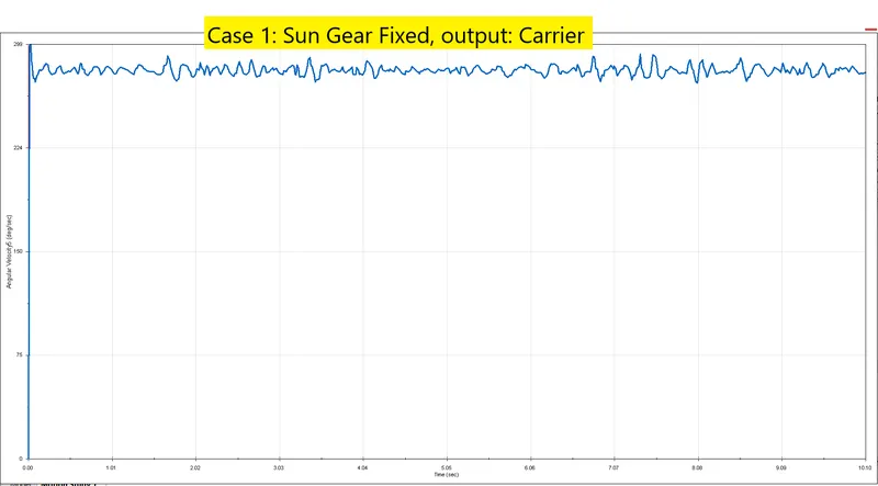
As the torque is provided to the sun gear, the angular velocity of the carrier increases rapidly and there is a small drop due to various components' motion and gear sliding, after that it's almost constant with minor jerks in motion. The planet gears not only rotate about their axis but are also forced to roll on the inside of the ring gear since it is fixed. This results in low speed and high torque transmitting capacity.
CASE 2: -
- Input:- Sun gear
- Output:- Ring gear
- Fixed- Carrier arm
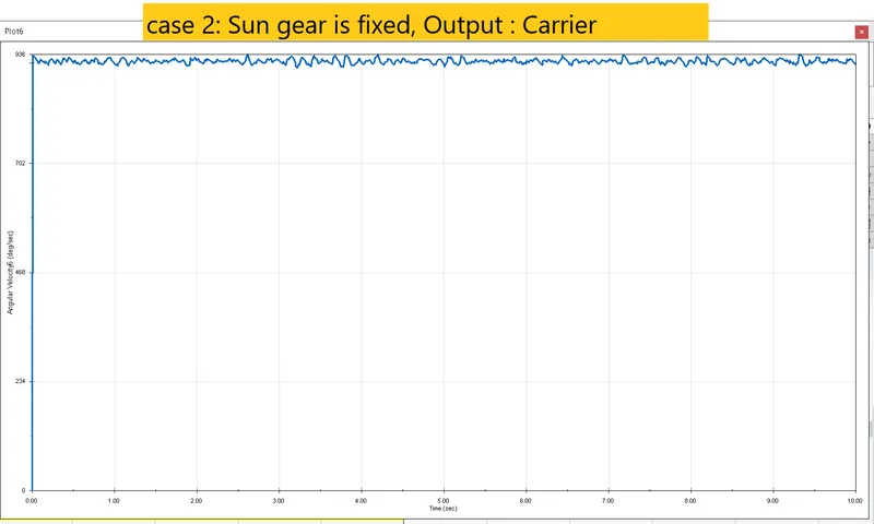
The planet gears rotate only about their own axis and transmit motion from Sun Gear to the Ring Gear and since the Ring gear is large in diameter. This results in low speed and high torque transmitting capacity.
CASE 3: -
- Input :-Ring gear
- Output :- Carrier arm
- Fixed-Sun gear
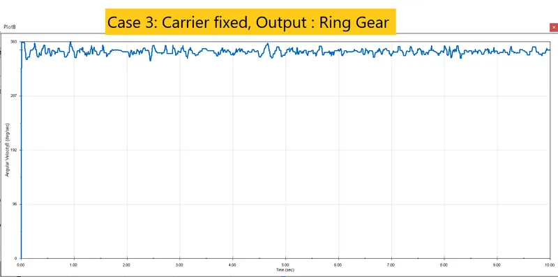
A planetary gear train as shown above. The Ring serves as the input to the train which has 46 teeth. The sun gear is the fixed gear and has 14 teeth. The planet gear has 16 teeth. The Carrier serves as the output from the train.
The Power is provided to ring gear, the angular velocity of the carrier increases rapidly and there is a small drop due to various components motion and gear sliding, after that it's almost constant with minor jerks in motion. The angular velocity of the carrier(output) is also quite large compared to other cases because of the meshing of planet gears and ring gear which results in large gear ratios because of their geometry. This results in high speed and low torque transmitting capacity.
CONCLUSIONS:- Compared with traditional fixed-shaft gearing systems, a planetary gearbox has a compact structure and lightweight, while its load-carrying capacity, transmission precision, and efficiency are much higher. Therefore, planetary gearboxes have been widely used in helicopters, wind turbines, mining machinery, and so forth