Photo Realistic Rendering
ASSEMBLY AND PHOTO REALISTIC RENDER OF AMERCIAN CHOPPER
OBJECTIVE:
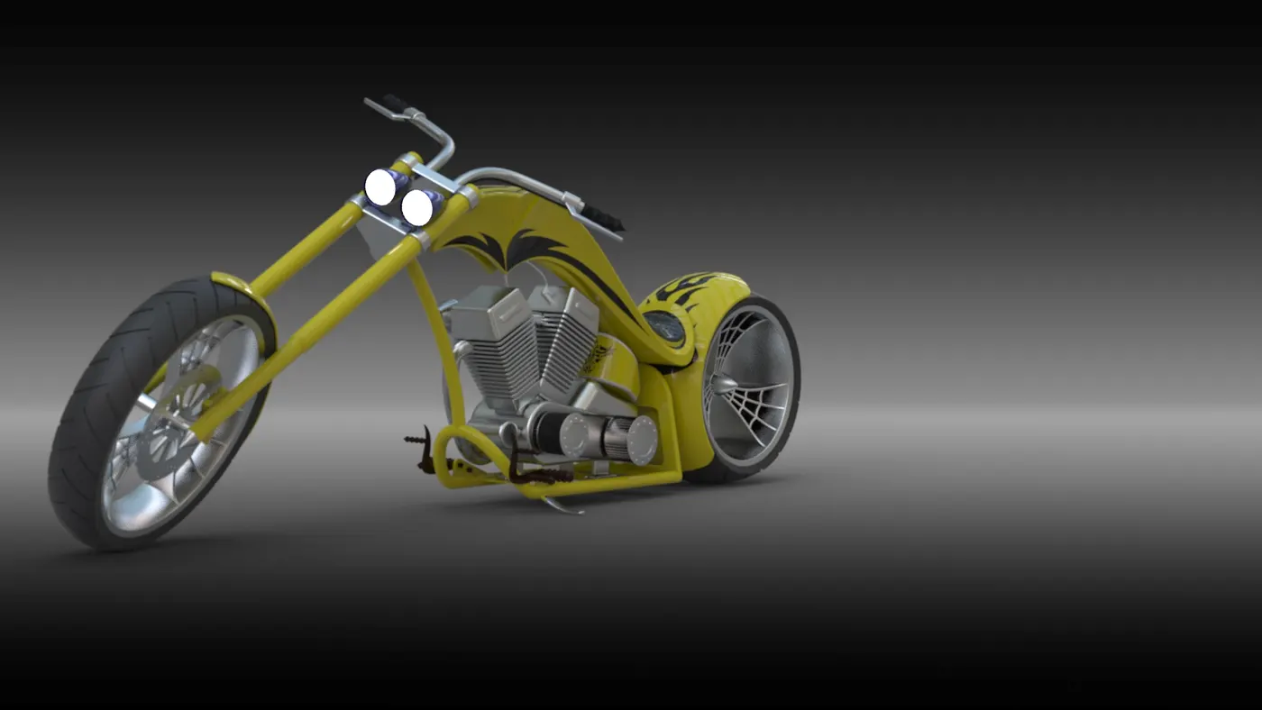
The main aim is to recreate the american chopper by modelling the parts and assmebling them using SOLID works and generate a photo realistic view using SOLIDWORKS Photo view 360 and solid works visualize.
Introduction:
Features are the individual shapes that, when combined, make up the part. You can also add some types of features to assemblies.Features include multibody part capability. You can include separate extrude, revolve, loft, or sweep features, within the same part document.
Some features originate as sketches,other features such as shells or fillets are created when we select the appropriate tool or menu command and define the dimensions or characteristics that we want. We can use the same sketch to create different features.Surfaces are another type of feature. We can use surfaces to create or modify solid features
Following are the different features used while creating the assembly
Sketch :
Sketch is a basic 2D layout of part to be converted.It consists of a basic tools like arc,rectangle,splines etc., which helps in creating a sketch.
Fillet :
Fillets are classified as applied features, and as such do not require a sketch to be used. Fillets serve to round off edges and/or corners by adding or removing material, depending on whether the edge is internal or external. It should be noted that fillets of different sizes must be created as separate features.
Mirror:
Mirror is used for replicating the one side of part to the other side in a selected plane.
Offset:
Offsets helps in replicating the drawn sketch at required distances.
Extrude boss and cut:
Extrude boss is used for transforming the 2D sketch into 3D model whereas the extrude cut helps in creating a required model by cutting the extruded part
Split:
Split tool is used for dividing a solid body into two different bodies.in this feature we can remove the unwanted solid bodies also.
Combine:
This feature helps in joining two different bodies as one by merging the surfaces of the bodies.
Convert entities:
We can create one or more curves in a sketch by projecting an edge, loop, face, curve, or external sketch contour, set of edges, or set of sketch curves onto the sketch plane.
Trim entities:
Trim is used to remove the unwanted areas for the model.mostly power trim is used for the purpose.
Dome:
Dome are applied on any planar faces whose centroid lies outside.
Lofts:
Loft creates a feature by making transitions between profiles. A loft can be a base, boss, cut, or surface.
Patterns:
Pattern repeats the selected features in an array based on a seed feature. You can create a linear pattern, a circular pattern, a curve driven pattern, a fill pattern, or use sketch points or table coordinates to create the pattern.The linear pattern creates multiple instances of a selected feature along a linear path where as the circular pattern creates a multipe instances radially along the path.
Revolves:
Revolves add or remove material by revolving one or more profiles around a centerline. we can create revolved boss/bases, revolved cuts, or revolved surfaces. The revolve feature can be a solid, a thin feature, or a surface.Revolved Boss feature, which adds material by revolving a sketch around an axis.
Shells:
The shell tool hollows out a part, leaves open the faces you select, and creates thin-walled features on the remaining faces.The Shell command allows us to define a wall thickness and automatically hollow the part, while allowing faces to be removed as needed. If no faces are specified to be removed during a Shell feature, the part will be hollow, but this can only be seen by creating a cross section of the part.
Surfaces:
Surfaces are a type of geometry that can be used to create solid features. Surface tools are available on the Surfaces toolbar.
Sweeps:
Sweep creates a base, boss, cut, or surface by moving a profile (section) along a path. A sweep can be simple or complex.
Curves:
Curves can be used as a path or guide curve for a sweep feature, as the guide curve for a loft feature, as a parting line for a draft feature. Here mostly projected curve and composite curves were used. Projected curve can project a sketched curve onto a model face to create a 3D curve. we can also create a 3D curve that represents the intersection of two extruded surfaces generated by creating sketches on two intersecting planes where as the composite curve is a combination of curves, sketch geometry, and model edges.
Appearances:
Appearances are used for recreating the model as per the actual model by changing the colour,texture,materails etc., It is handy tool for creating any model.
Parts used in american chopper:
1.Engine
2.Chasis
3.Kick stand
4.Gas tank
5.Oil tank
6.Rear and front wheels
7.Transmission belt
8.Chain link
9.pedal
10.Front Fork
11.Front and rear fender
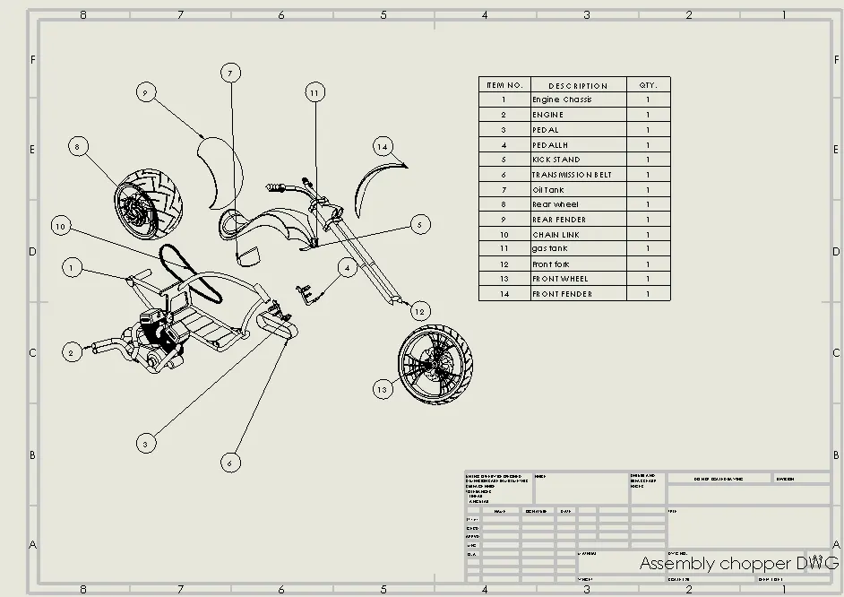
Detail description of parts
1.Engine:
Engine is the heart of automotive vehicle used in driving it. it converts the input thermal energy into mechanical power. There are many types of engines used for the reuired purposes.
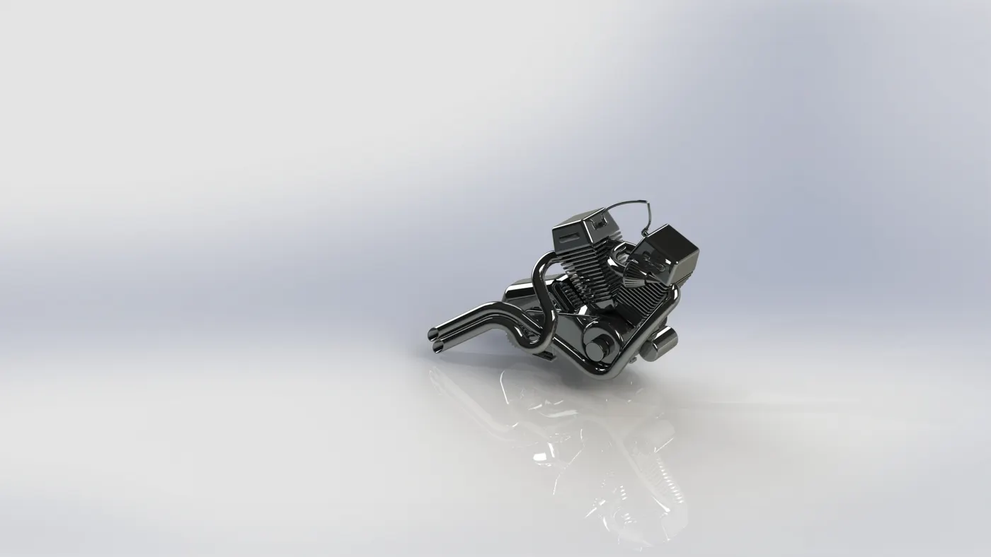
Following were the features used in modelling a Engine:
a.Projected curve
b.extruded boss
c.fillet.
d.extruded cut
e.revolve
f.linear and circular pattern.
g.mirror
h.sweep.
2.Engine chasis:
A chasis is the main supporting structure of the vehicle to which all the parts are attached which was mostly made up off aluminium alloys or carbon steel.It deals with the static and dynamic loads without any deflection or distortion which includes the weight of the passengers,cargo loads, torque from engine and transmission, impact from collisions.
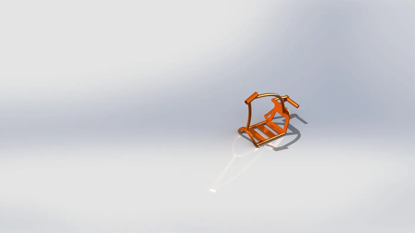
Following were the features used in modelling a chasis:
a.revolve
b.projected curve
c.mirror
d.fillet
e.extrude boss
f.combine
g.split
h.swept
3.kick stand:
A kick stand is the device that allows the bike to be keep it upright.It is usually a piece of metal that flips down from the frame.It is made up of steel or aluminium.
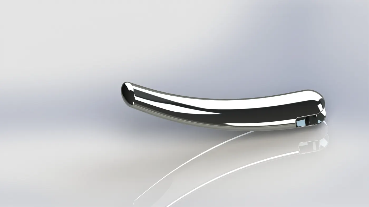
Following were the features used in modelling a kick stand:
a.Loft
b.Dome
c.Extrude cut
d.Split
e.Boss extrude
f.Fillet
4.Gas tank:
Gas tank acts as an fuel resorvoir for the engine.It stores the flammable fluids without exposing it to the surroundings.
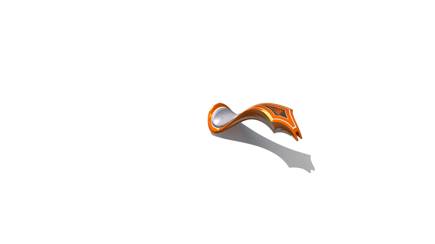
Following were the features used in modelling a gas tank:
a.Loft
b.Projected curve
c.Swept
d.Split
e.Mirror
f.Fillets
g.Reference planes
5.Oil tank:
Oil tank is used for the storage of the lubrication oil necessary for the mating areas of the bike.
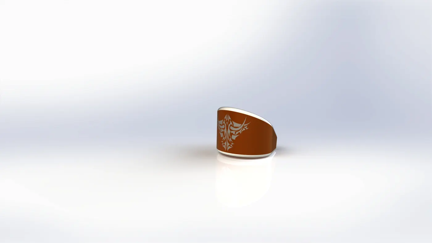
Following were the features used in modeling a Oil tank:
a.Fillet
b.Shell
c.Combine.
d.extrude boss
6.Pedal:
Pedal is used for the shifting of gears for acquiring necessary speeds at required times.
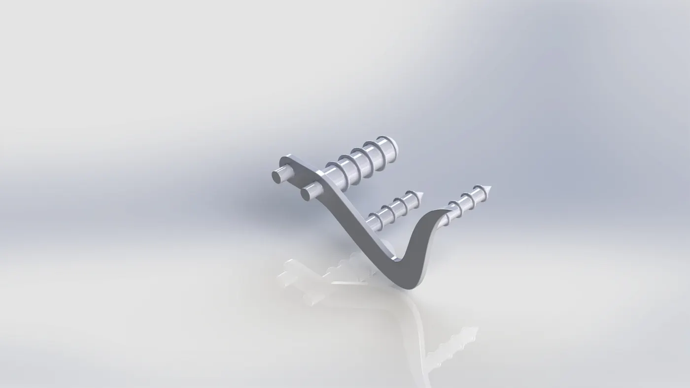
Following were the features used in modeling a pedal:
a.Extruded boss
b.Fillet
c.Revolved boss
d.Dome
e.Chamfer
f.Linear pattern
7.Chain link:
A chain is used for transmitting the power of front wheel to the rear wheel.it consists of series of cylindrical rollers held together by side links.
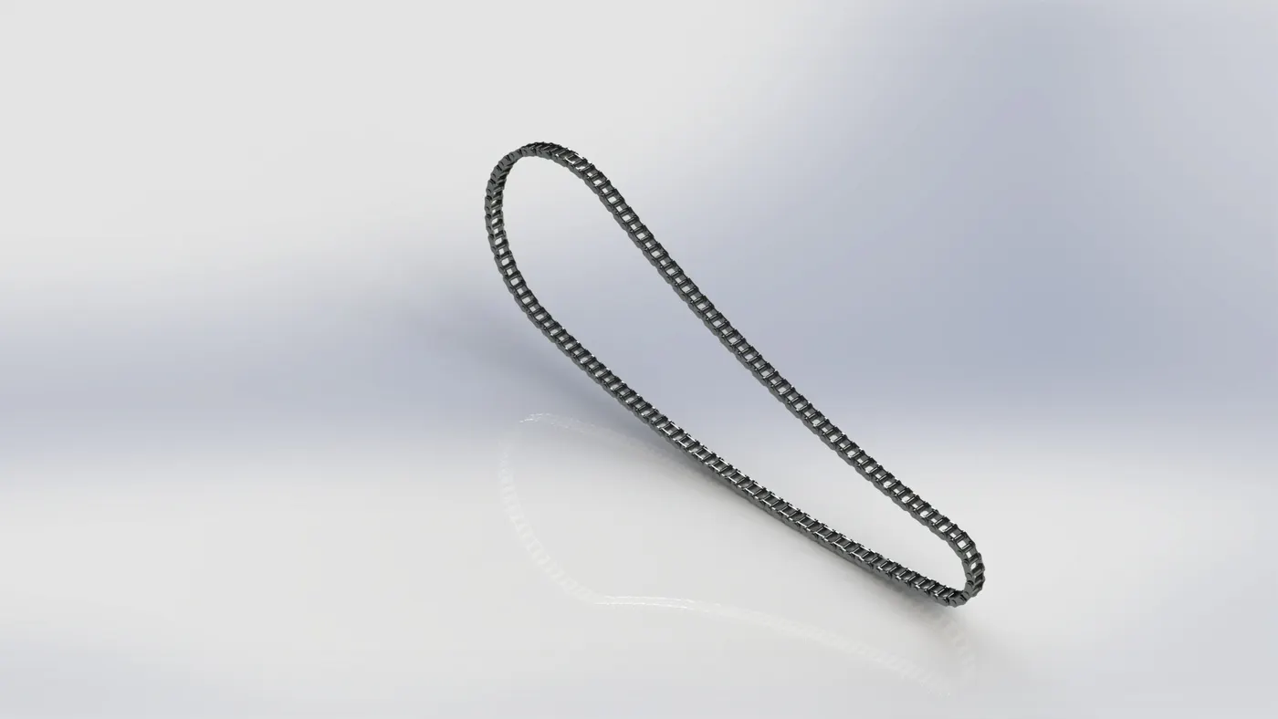
Following were the features used in modelling a Chain:
a.Extruded boss
b.Fillet
c.Projected curves
d.curve pattern
e.Mirror
f.Blocks
8.Transmission belt:
Belt drives are generally used where nosie free smooth transmission required.it is made up of rubber type material consisting of a toothed profile overall on the inner side of the belt.
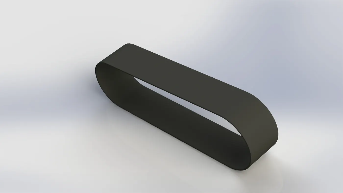
Following were the features used in modelling a Belt:
a.Extruded boss
b.Fillet
c.merge
9.Front Fork:
A bike fork is used for holding the front wheel. the parts of fork are held as one with the help of fork crown.
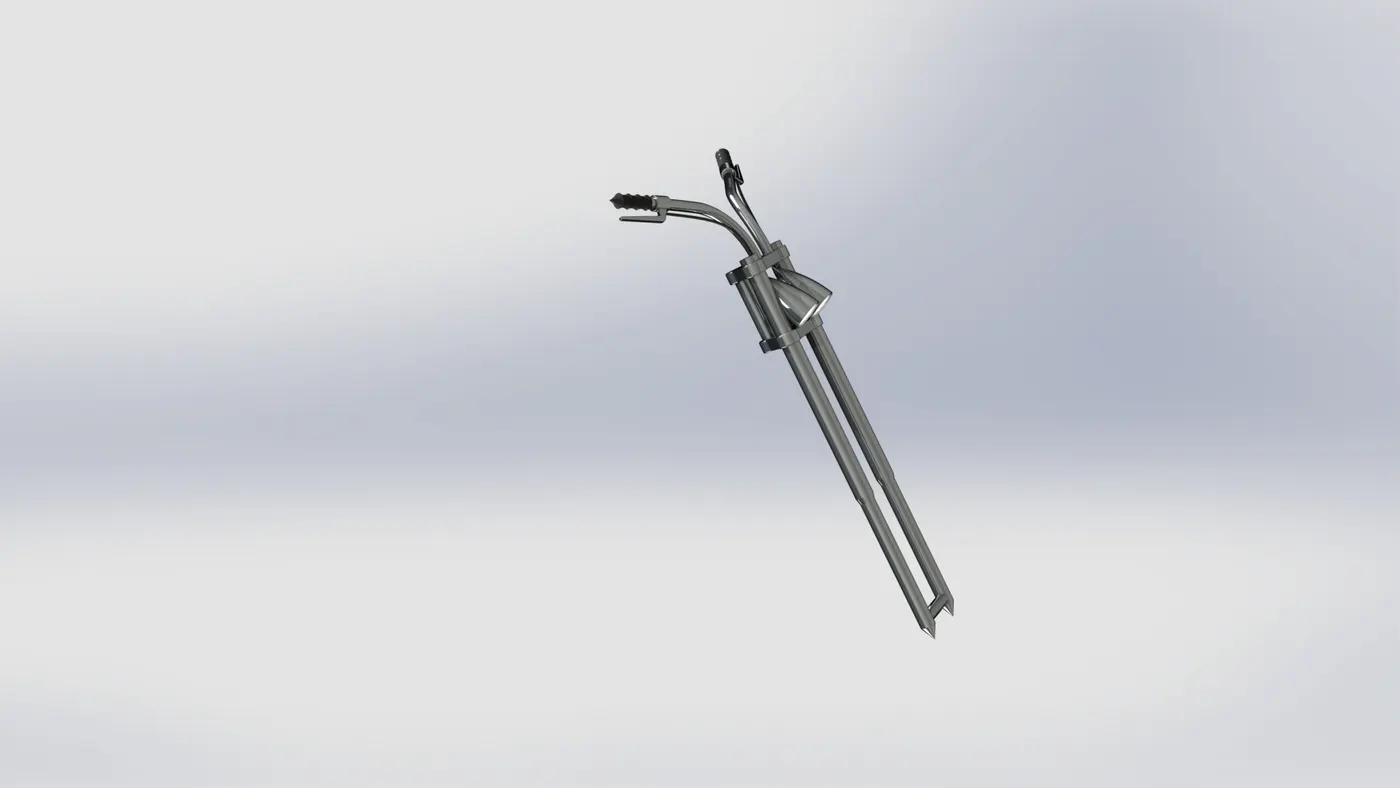
Following were the features used in modelling a Front fork:
a.Extruded boss
b.Fillet
c.Extruded cut
d.projected curve
e.Dome
f.swept
g.Mirror
h.combine
10.Front wheel:
Wheels are made to cope with the radial and axial forces.high performance motorcycles began to cast alloy wheels for better rigidity,better retention,elimination of spokes etc., The main function of the front wheel is to take the impact and steer the motorcycle.
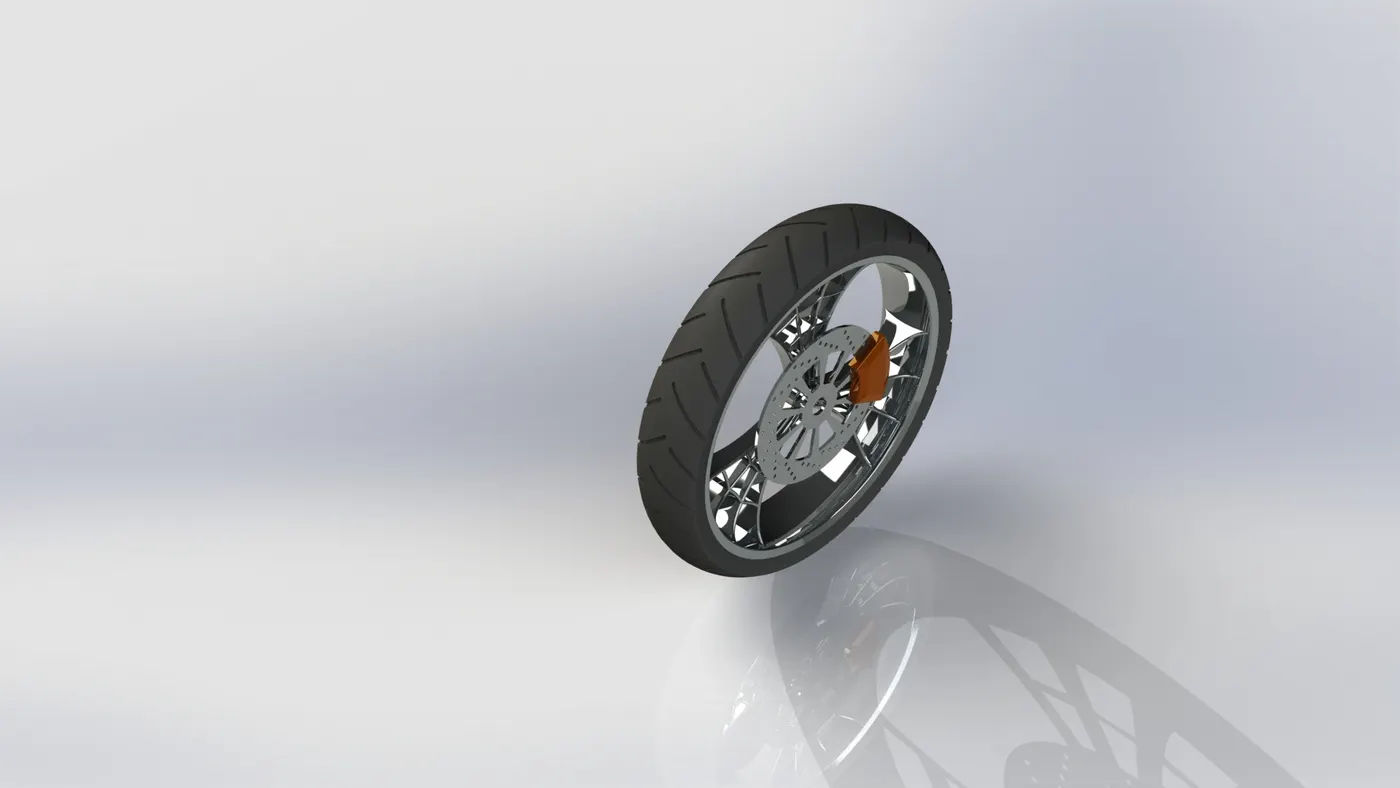
Following were the features used in modelling a Front wheel:
a.Extruded boss
b.Fillet
c.Extruded cut
d.Revolve
e.Circular pattern
f.combine
11.Rear wheel:
Wheels are made to cope with the radial and axial forces.high performance motorcycles began to cast alloy wheels for better rigidity,better retention,elimination of spokes etc.,The motorcycle engine power is all given to the rear wheel whihc enables the vehicle to move.the wider the back wheel the more more surface area which touches the road increasing in traction.
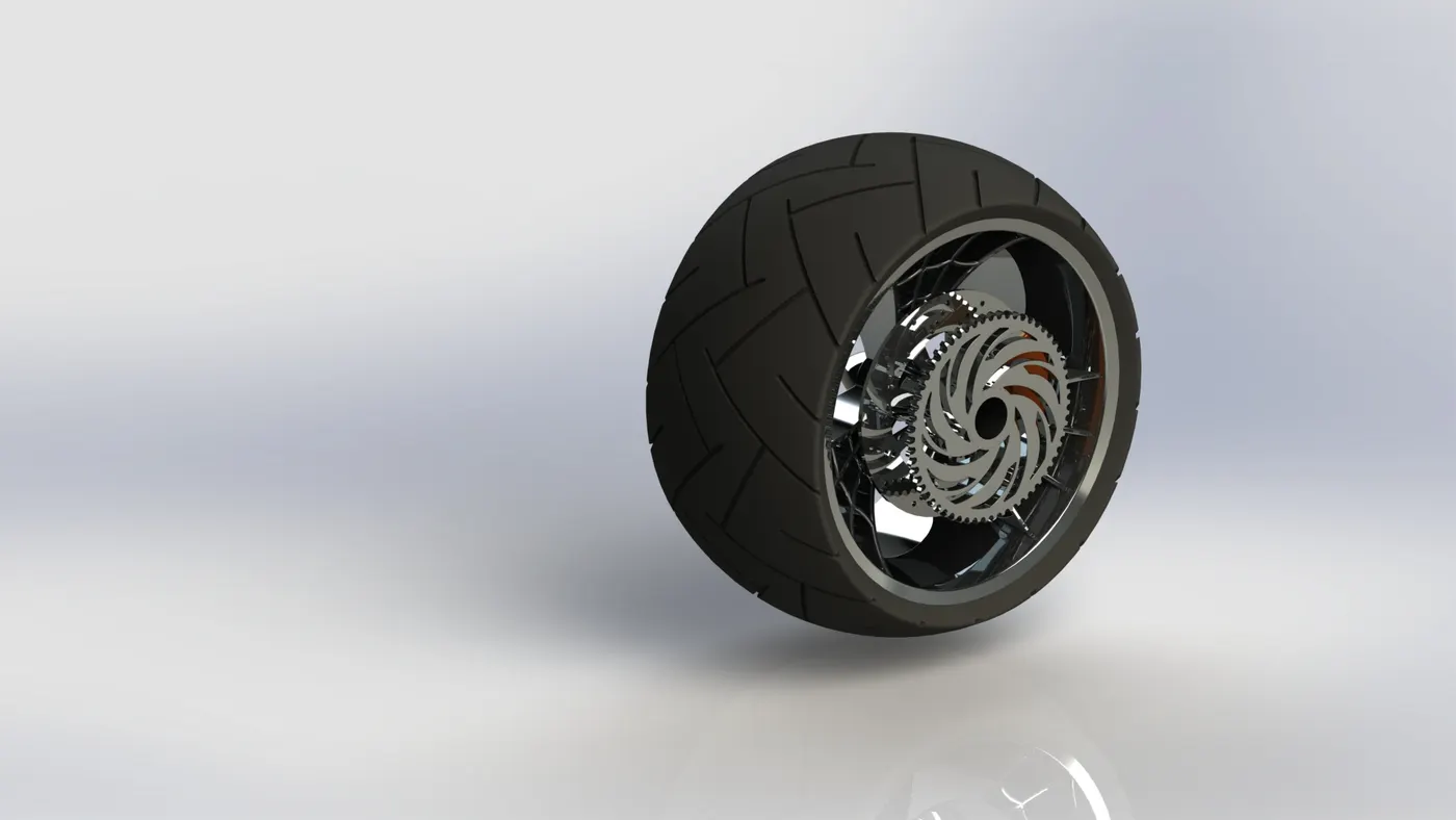
Following were the features used in modelling a Rear wheel:
a.Extruded boss
b.Fillet
c.Extruded cut
d.Revolve
e.Circular pattern
f.combine
12.Front fender:
The primary purpose of the fender is to prevent the sand, mud etc., from being thrown into the air by rotating tyre. These are basically rigid and can be damaged by contact with the road surface.In british english the fender is called the wing.
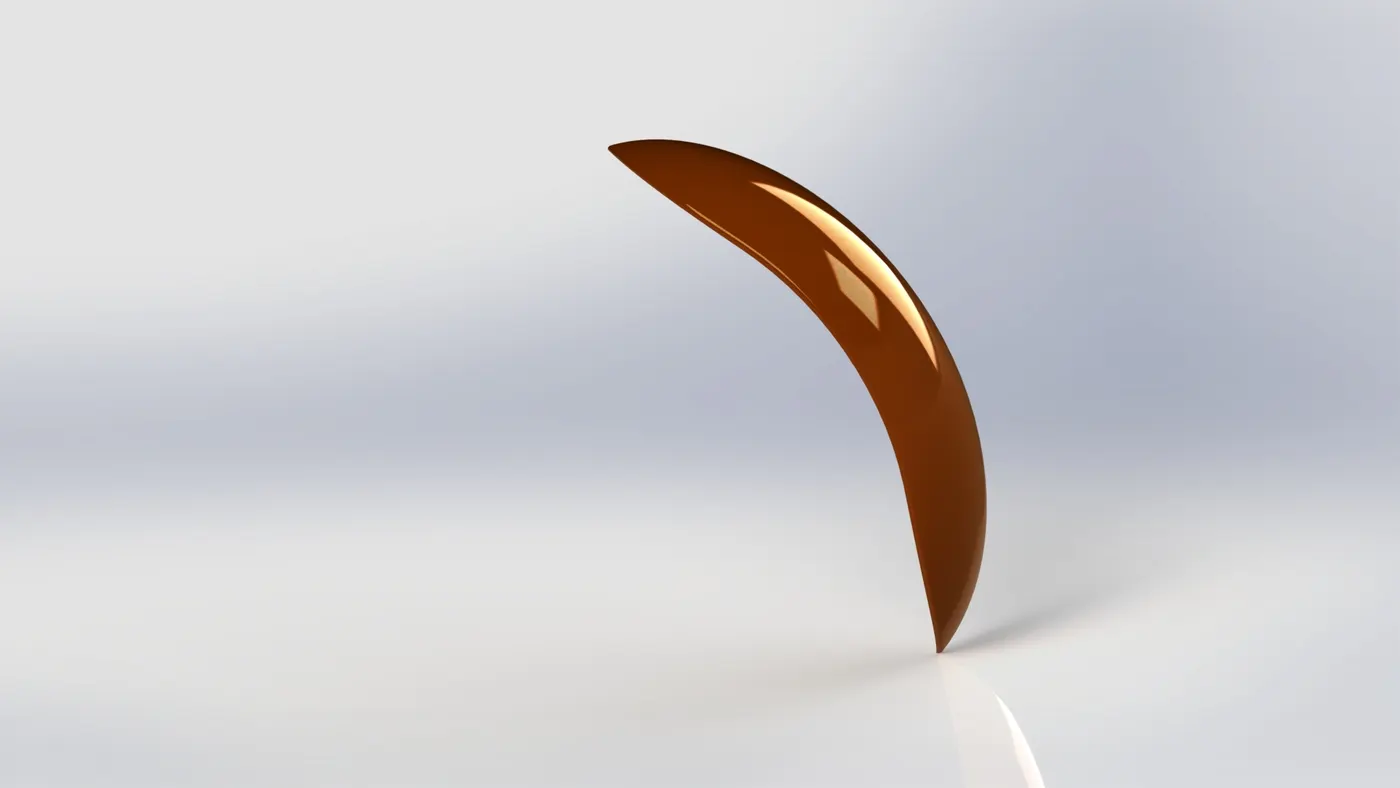
Following were the features used in modelling a Front fender:
a.Revolved boss
b.split
c.shell
13.Rear fender:
The primary purpose of the fender is to prevent the sand, mud etc., from being thrown into the air by rotating tyre. These are basically rigid and can be damaged by contact with the road surface.In british english the fender is called the quarter panels.
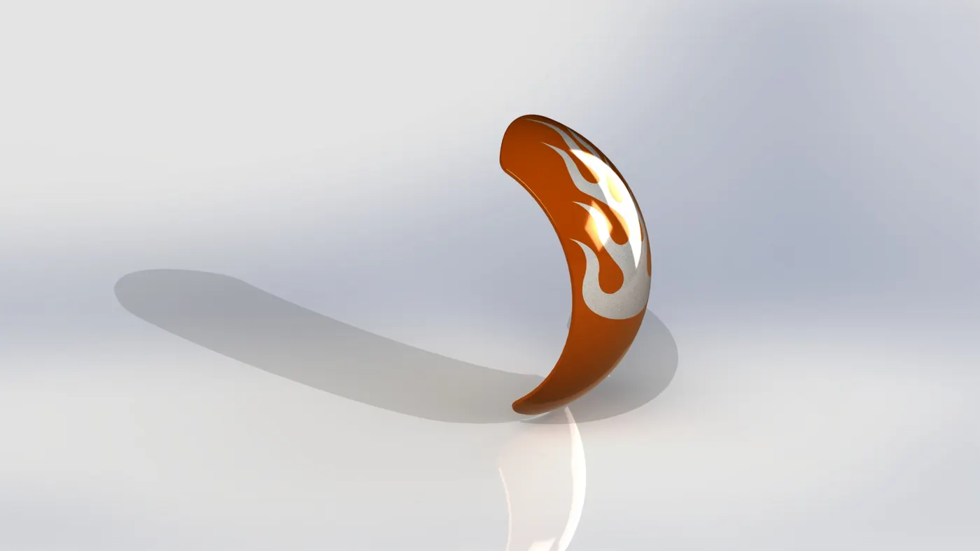
Following were the features used in modelling a Rear fender:
a.Revolved boss
b.split
c.shell
Assembly of American chopper:
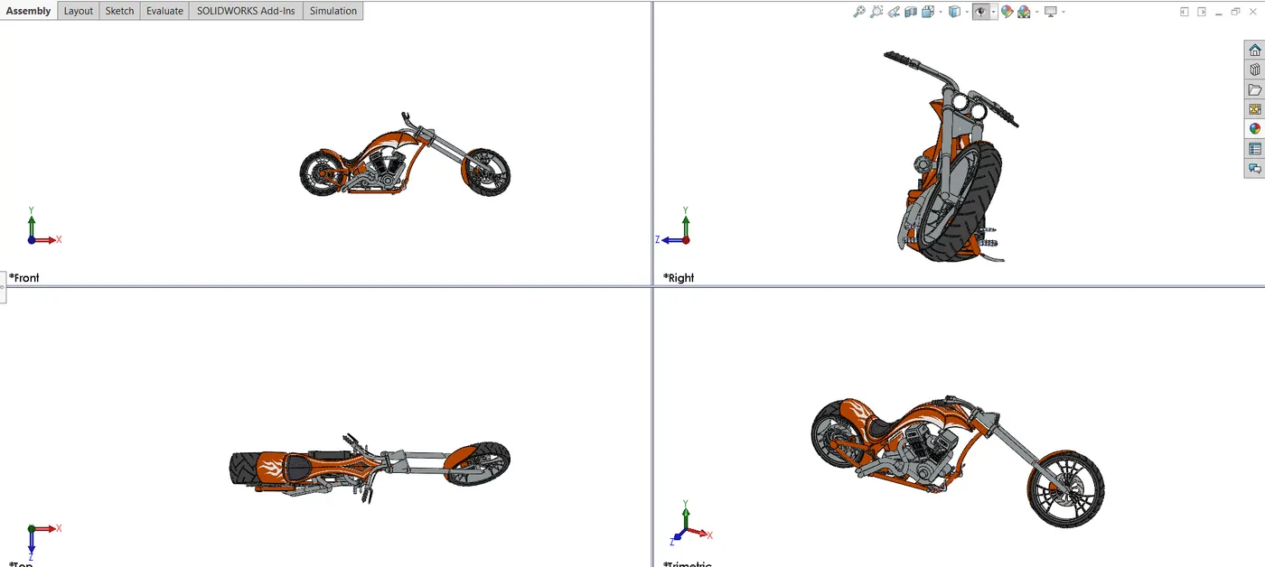
An assembly is a collection of related parts. The components in an assembly are defined in relation to each other using assembly mates. we can attach the assembly components using various types of mates such as coincident, concentric, and distance mates. For example, the engine components are mated to the Chasis as base component using concentric and coincident mates. The
mated components create the subassembly. Later, you include this subassembly in the main assembly, mating it to the other components in the assembly.
Mates:
Mates position the components in an assembly precisely with respect to each other. Positioning the components defines how they move and rotate with respect to each other.Mates create geometric relations, such as coincident, perpendicular, and tangent. Each mate is valid for specific combinations of geometry such as cones, cylinders, planes, and
extrusions. For example, if you mate a cone to another cone, the valid types of mates you can use include coincident, concentric, and distance etc.,
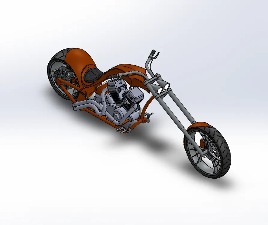
For this model I used the chasis as the base component for setting up a reference and with the of coincident mate combined the engine parts and chasis as one.
Add on to that other parts were mated and made into a full assembly.
Rendering of Model:
Rendering is the process of generating a photrealistic or non photorealistic image.The scene file contains geometry, viewpoint, texture, lightning, and shading information describing the virtual scene. The data contained in the scene file is then passed to a rendering program to be processed and output to a digital image or raster graphics image file. The term "rendering" is also used to describe the process of calculating effects in a video editing program to produce the final video output.
PhotoView 360 is a SolidWorks add-in that produces photo-realistic renderings of SolidWorks models. The rendered image incorporates the appearances, lighting, scene, and decals included with the model. PhotoView 360 is available with SolidWorks Professional or SolidWorks Premium.
-
PhotoView provides two ways to preview renders: in the graphics area (Integrated Preview) and in a separate window (Preview Window). Both methods help you assess changes quickly before performing a full render. Because updates are continuous, you can experiment with controls that affect rendering without fully understanding the purpose of each control.
-
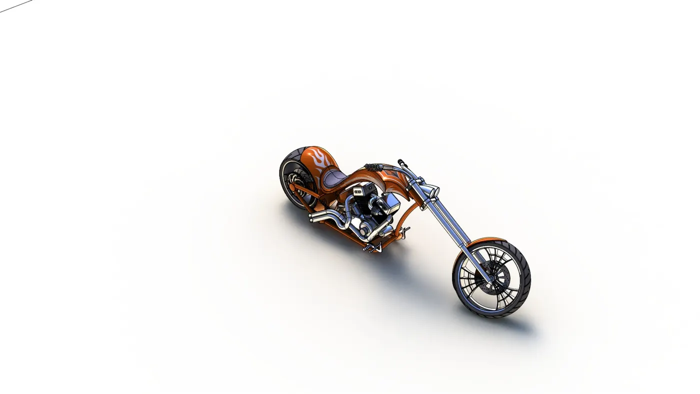
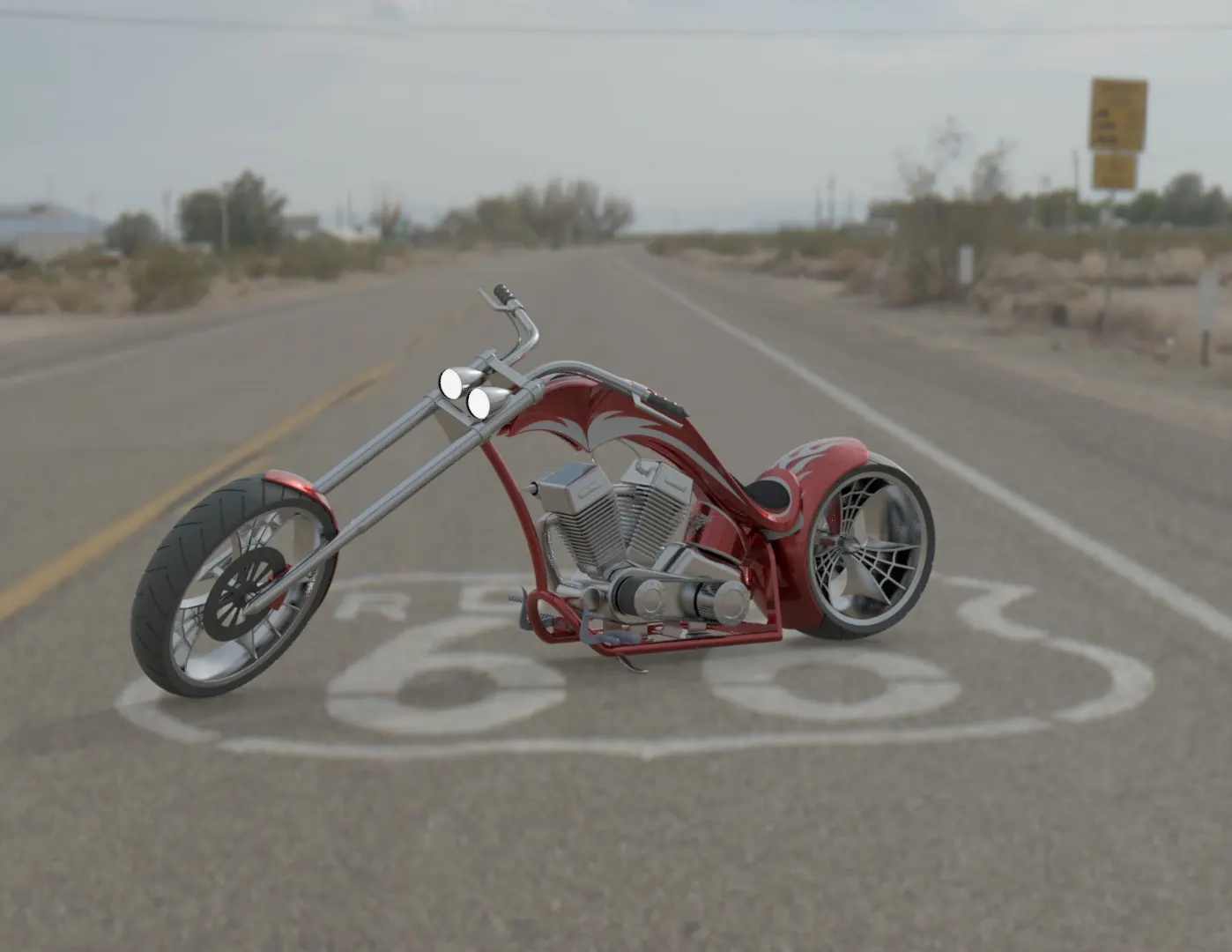
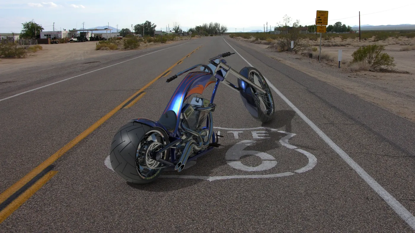
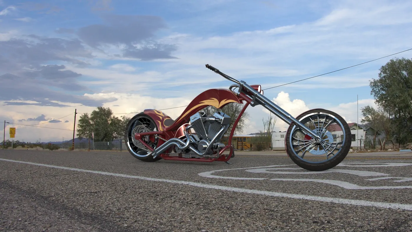
The below model has been renderedd using solidworks visualise and Photoview 360.
-
The assembly has been imported to solidworks visualise to create a realistic view. The apperances has been modified here by creating a set environment according to it for making it look realistic.
- Hence the final rendering has been done and below were some of the rendered items.
Conclusion:
Hence i conclude that creating a prototype by modelling the individual parts and uniting them as one by using different features in solidworks . In fact modelling in general terms leads to generalising a virtual prototype inorder to modify the parts and understanding the issues occured while assembling instead of solving it on actual part which results in reducing of cost and time.