Assembly of Yacht
ASSEMBLY AND PHOTO REALISTIC RENDER OF YATCHT
OBJECTIVE:
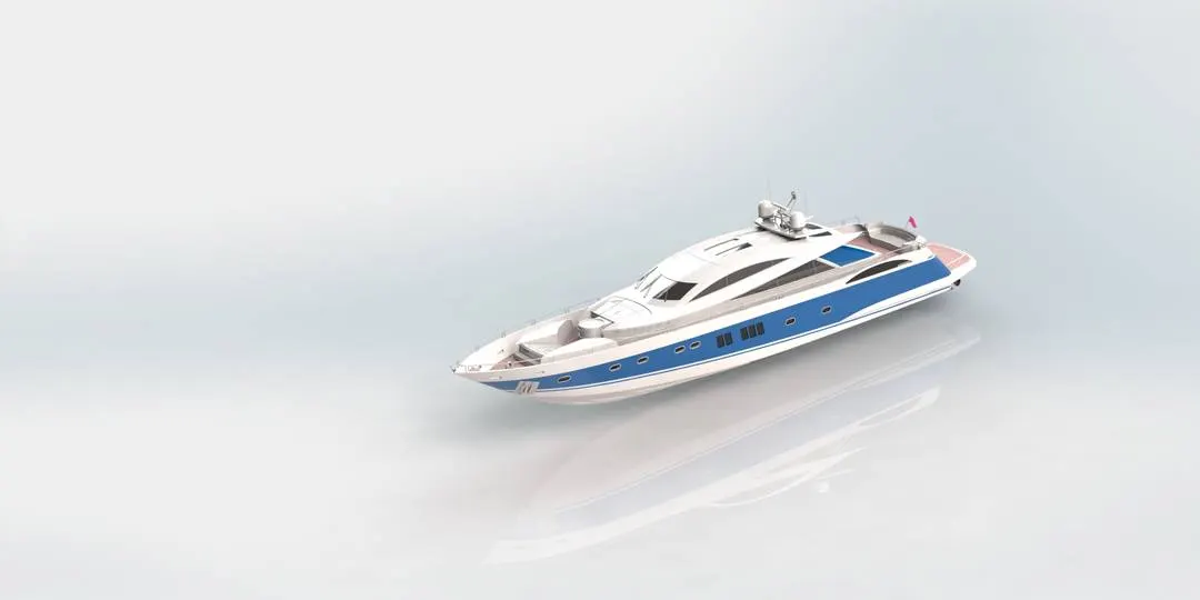
The main aim is to recreate the Yatcht by modelling the parts and assmebling them using Solid works and generate a photo realistic view using SOLIDWORKS Photo view 360 and solid works visualize.
INTRODUCTION:
Features are the individual shapes that, when combined, make up the part. You can also add some types of features to assemblies.Features include multibody part capability. You can include separate extrude, revolve, loft, or sweep features, within the same part document.
Some features originate as sketches,other features such as shells or fillets are created when we select the appropriate tool or menu command and define the dimensions or characteristics that we want. We can use the same sketch to create different features.Surfaces are another type of feature. We can use surfaces to create or modify solid features
Following are the different features used while creating the assembly:
Sketch :
Sketch is a basic 2D layout of part to be converted.It consists of a basic tools like arc,rectangle,splines etc., which helps in creating a sketch.
Fillet :
Fillets are classified as applied features, and as such do not require a sketch to be used. Fillets serve to round off edges and/or corners by adding or removing material, depending on whether the edge is internal or external. It should be noted that fillets of different sizes must be created as separate features.
Mirror:
Mirror is used for replicating the one side of part to the other side in a selected plane.
Offset:
Offsets helps in replicating the drawn sketch at required distances.
Extrude boss and cut:
Extrude boss is used for transforming the 2D sketch into 3D model whereas the extrude cut helps in creating a required model by cutting the extruded part
Split:
Split tool is used for dividing a solid body into two different bodies.in this feature we can remove the unwanted solid bodies also.
Combine:
This feature helps in joining two different bodies as one by merging the surfaces of the bodies.
Convert entities:
We can create one or more curves in a sketch by projecting an edge, loop, face, curve, or external sketch contour, set of edges, or set of sketch curves onto the sketch plane.
Trim entities:
Trim is used to remove the unwanted areas for the model.mostly power trim is used for the purpose.
Dome:
Dome are applied on any planar faces whose centroid lies outside.
Lofts:
Loft creates a feature by making transitions between profiles. A loft can be a base, boss, cut, or surface.
Fill:
surface fill constructs a surface patch with any number of sides, within a boundary defined by existing model edges, sketches or curves.
Patterns:
Pattern repeats the selected features in an array based on a seed feature. You can create a linear pattern, a circular pattern, a curve driven pattern, a fill pattern, or use sketch points or table coordinates to create the pattern.The linear pattern creates multiple instances of a selected feature along a linear path where as the circular pattern creates a multipe instances radially along the path.
Revolves:
Revolves add or remove material by revolving one or more profiles around a centerline. we can create revolved boss/bases, revolved cuts, or revolved surfaces. The revolve feature can be a solid, a thin feature, or a surface.Revolved Boss feature, which adds material by revolving a sketch around an axis.
Shells:
The shell tool hollows out a part, leaves open the faces you select, and creates thin-walled features on the remaining faces.The Shell command allows us to define a wall thickness and automatically hollow the part, while allowing faces to be removed as needed. If no faces are specified to be removed during a Shell feature, the part will be hollow, but this can only be seen by creating a cross section of the part.
Surfaces:
Surfaces are a type of geometry that can be used to create solid features. Surface tools are available on the Surfaces toolbar. examples are surface fill,offset,sweep, loft,knit,trim,extrude etc.,
Sweeps:
Sweep creates a base, boss, cut, or surface by moving a profile (section) along a path. A sweep can be simple or complex.
Curves:
Curves can be used as a path or guide curve for a sweep feature, as the guide curve for a loft feature, as a parting line for a draft feature. Here mostly projected curve and composite curves were used. Projected curve can project a sketched curve onto a model face to create a 3D curve. we can also create a 3D curve that represents the intersection of two extruded surfaces generated by creating sketches on two intersecting planes where as the composite curve is a combination of curves, sketch geometry, and model edges.
Appearances:
Appearances are used for recreating the model as per the actual model by changing the colour,texture,materails etc., It is handy tool for creating any model.
Parts used in yatcht:
1.Hull
2.Superstructure
3.Front seat
4.Middle seat
5.Rear seat
6.Radar
7.Radar Mast
8.Garage door
9.Propeller
Detail description of parts:
1.Hull:
Hull is the notable structure of the ship.It is the water tight enclousre of the ship,which protects the cargo,machinery and accommodation spaces of the ship from the weather, flooding and structural damage.
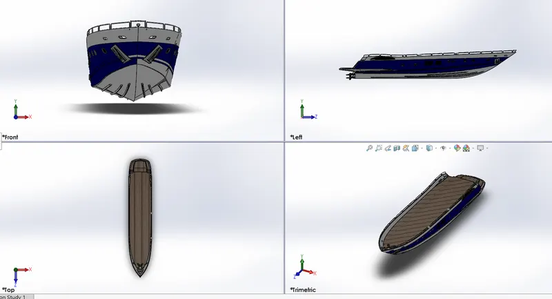
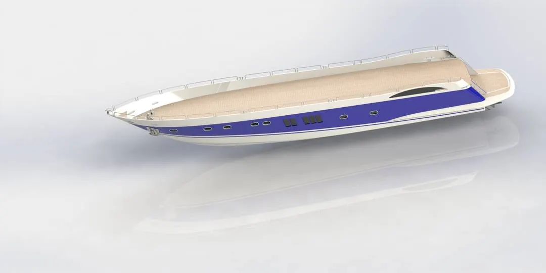
Following were the features used in modelling a Hull:
a.projected curve
b.surface extrude
c.fillet.
d.extruded cut
e.surface fill
f.linear pattern.
g.mirror
h.sweep.
i.loft.
h.surface knit
l.surface trim
m.shell
2.Super structure:
A super structure is an upward extension of an existing structure above the hull. The superstructure can have many implications in their performance of ships and boats, since the structures can alter their structural rigidity, their displacements and stability.
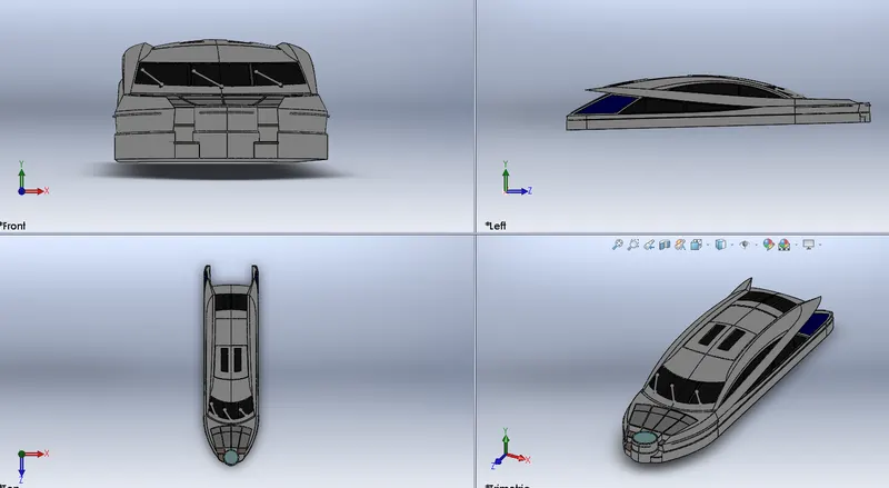
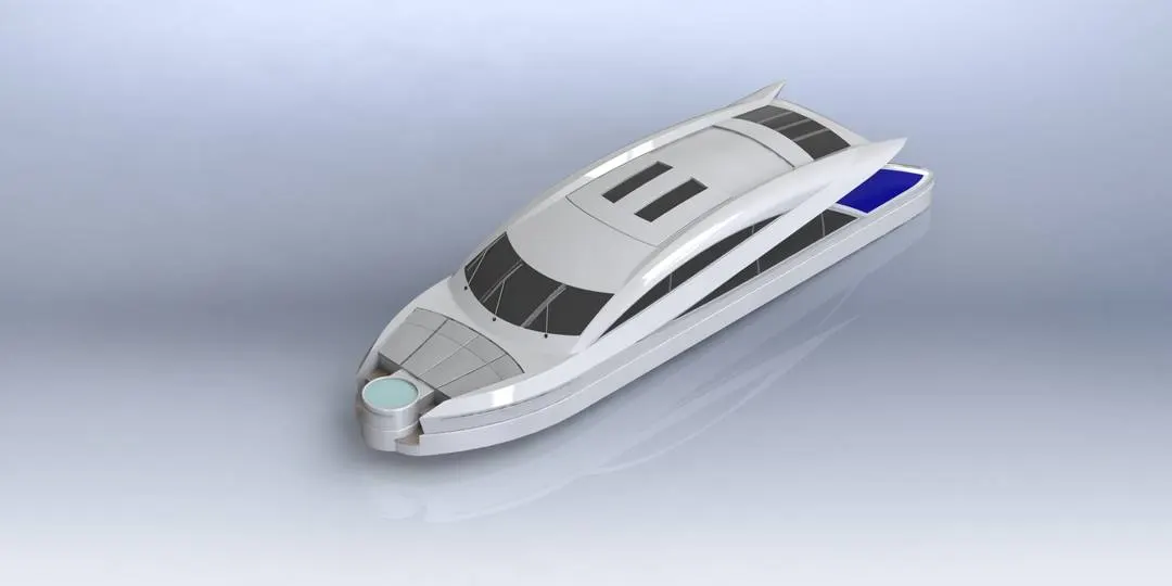
Following were the features used in modelling a superstructure:
a.Cut extrude
b.projected curve
c.mirror
d.fillet
e.surface extrude
f.surface knit
g.Surface fill
h.swept
i.3D sketch
j.linear pattern
k.boss extrude
3.Front seat:
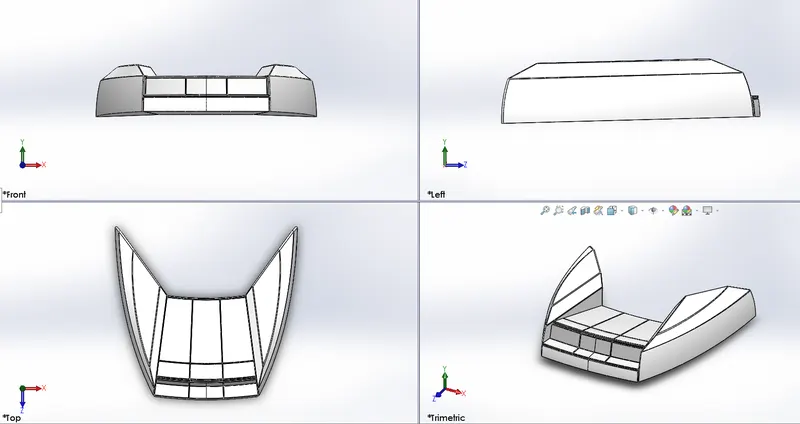
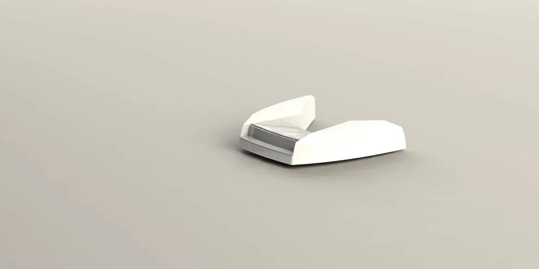
Following were the features used in modelling a Front seat:
a.Loft
b.Surface sweep
c.Extrude cut
d.Surface fill
e.Boss extrude
f.Fillet
g.Surface knit
h.revolve
4.Middle seat:
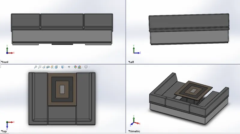
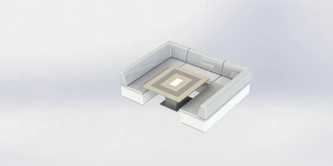
Following were the features used in modelling a Middle seat:
a.Boss extrude
b.cut extrude
c.Chamfer
d.fillet
e.mirror
5.Rear seat:
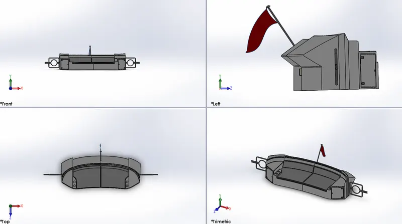
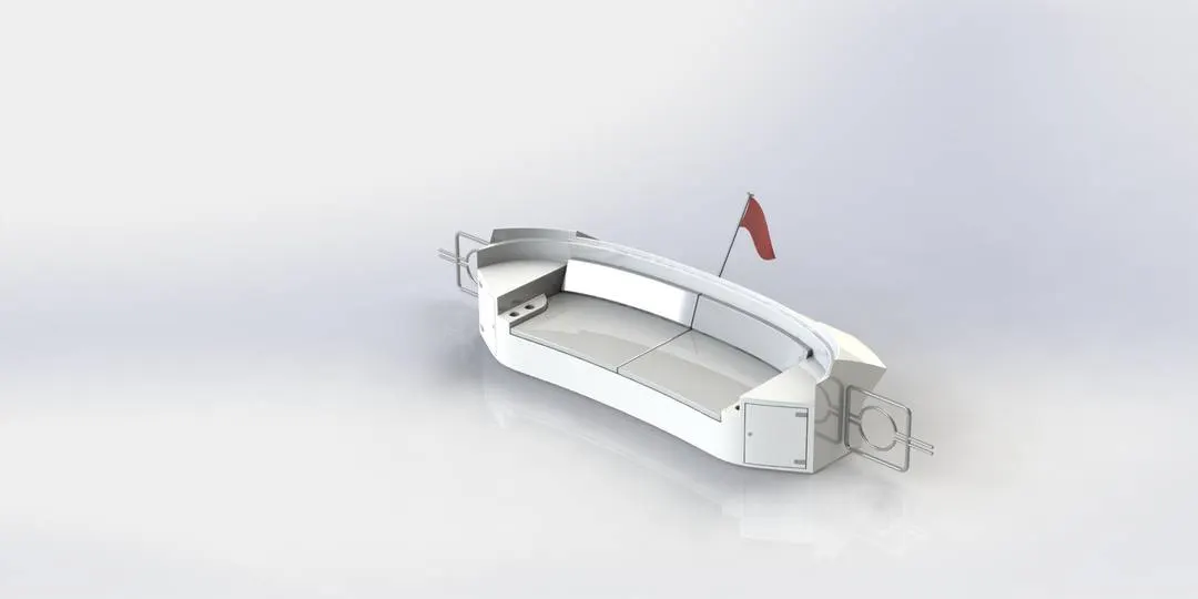
Following were the features used in modeling a Rear seat:
a.Loft
b.Surface sweep
c.Extrude cut
d.Surface fill
e.Boss extrude
f.Fillet
g.Surface knit
h.surface offset
i.ruled surface
6.Radar:
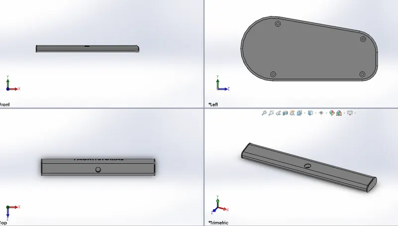
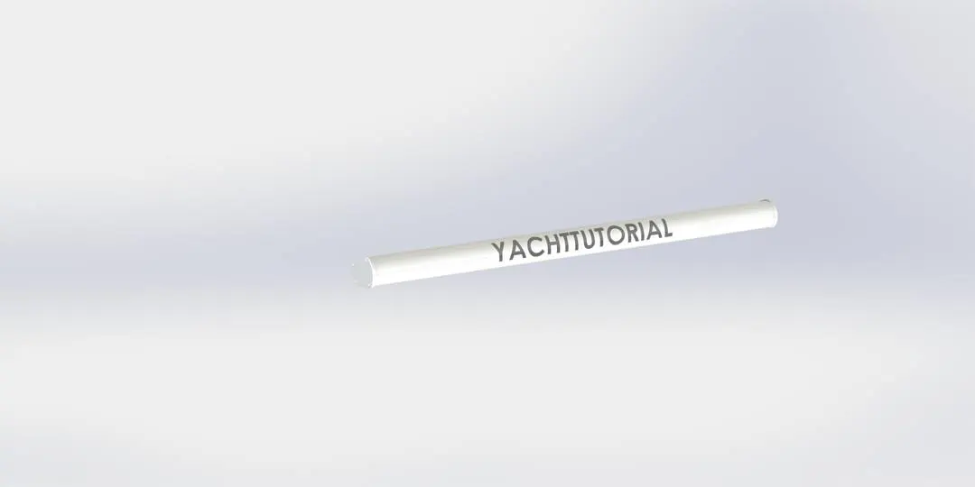
Following were the features used in modeling a Radar:
a.Extruded boss
b.Fillet
c.Linear pattern
d.Extrude cut
e.Mirror
7.Radar Mast:
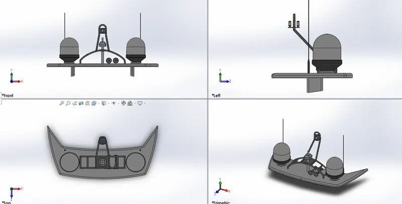
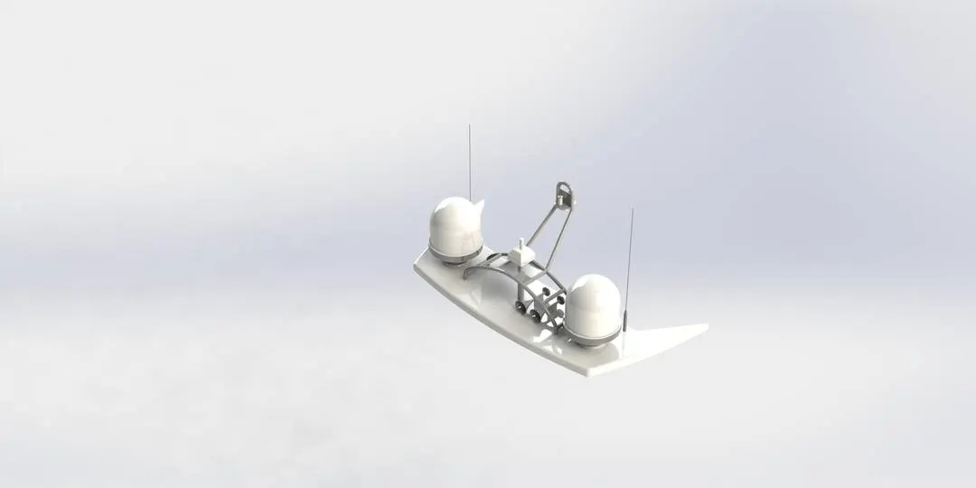
Following were the features used in modelling a Radar mast:
a.Extruded boss
b.Fillet
c.Sweep
d.Revolve
e.Mirror
f.Projected curves
8.Garage door:
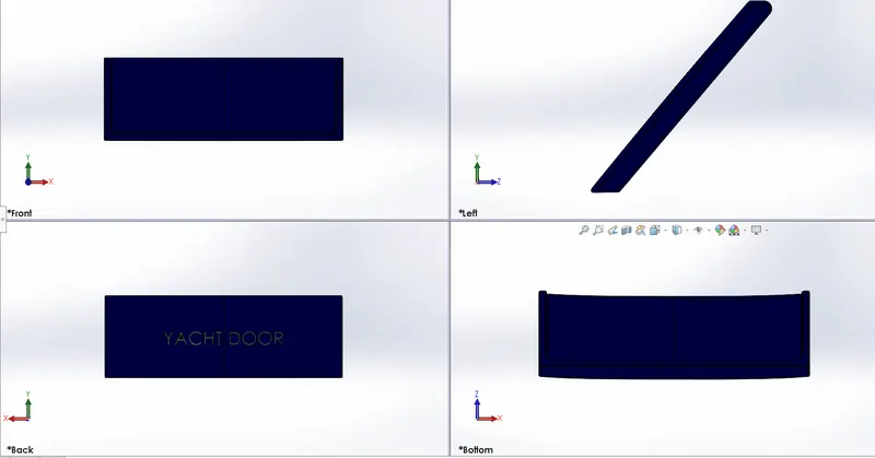
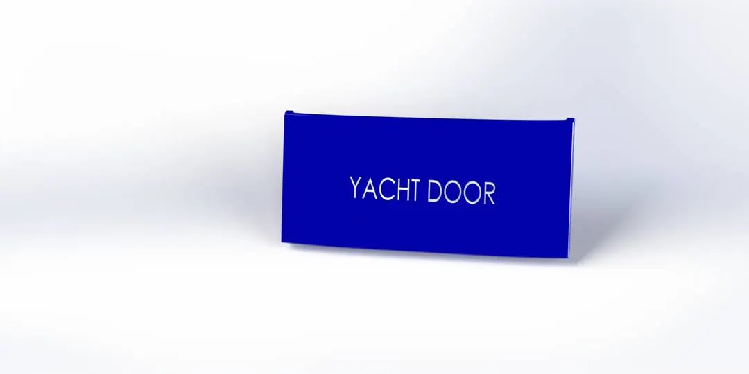
Following were the features used in modelling a Garage door:
a.Extruded cut
b.Fillet
c.Mirror
9.Propeller:
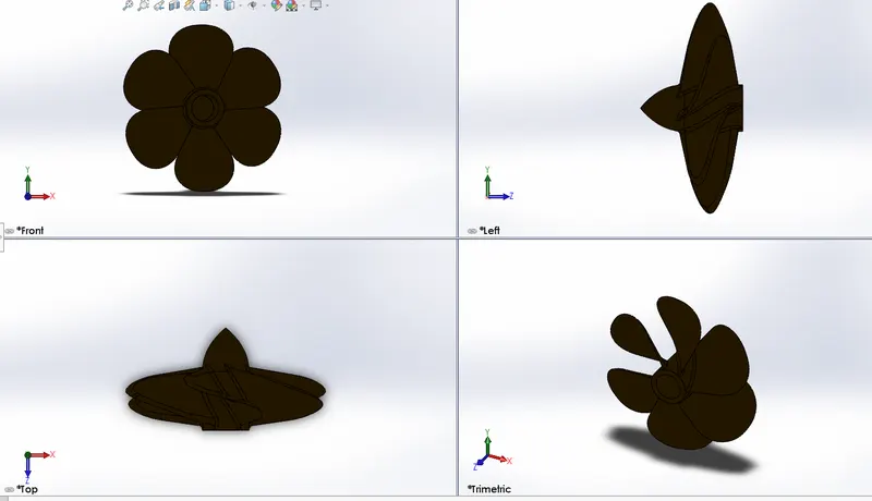
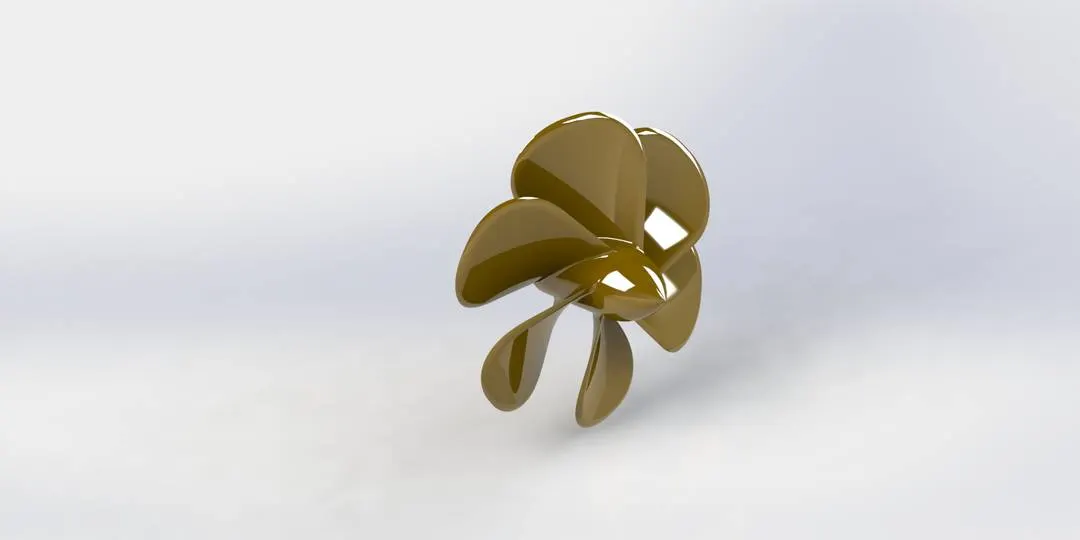
Following were the features used in modelling a Propeller:
a.Cut extrude
b.Loft
c.Circular pattern
d.Fillet
e.Revolve
Assembly of Yatcht:
Mates:
Mates position the components in an assembly precisely with respect to each other. Positioning the components defines how they move and rotate with respect to each other.Mates create geometric relations, such as coincident, perpendicular, and tangent. Each mate is valid for specific combinations of geometry such as cones, cylinders, planes, and
extrusions. For example, if you mate a cone to another cone, the valid types of mates you can use include coincident, concentric, and distance etc.,
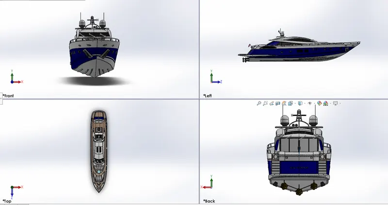
For this model I used the hull as the base component for setting up a reference and with the help of coincident mate combined the other parts and converted to a full assembly.
Below are the mates used :
Distance mate used for placing the Hull ,rear seat and propeller
coincident mate used for hull, garage door seats,superstructure
concentric mate used for combining the propellor, radar mast and radar
Rendering of Model:
Rendering is the process of generating a photrealistic or non photorealistic image.The scene file contains geometry, viewpoint, texture, lightning, and shading information describing the virtual scene. The data contained in the scene file is then passed to a rendering program to be processed and output to a digital image or raster graphics image file. The term "rendering" is also used to describe the process of calculating effects in a video editing program to produce the final video output.
PhotoView 360 is a SolidWorks add-in that produces photo-realistic renderings of SolidWorks models. The rendered image incorporates the appearances, lighting, scene, and decals included with the model. PhotoView 360 is available with SolidWorks Professional or SolidWorks Premium.
PhotoView provides two ways to preview renders: in the graphics area (Integrated Preview) and in a separate window (Preview Window). Both methods help you assess changes quickly before performing a full render. Because updates are continuous, you can experiment with controls that affect rendering without fully understanding the purpose of each control.
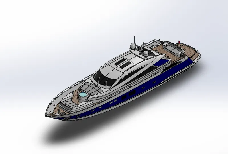
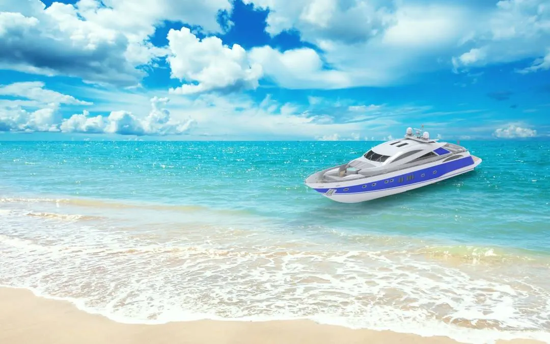
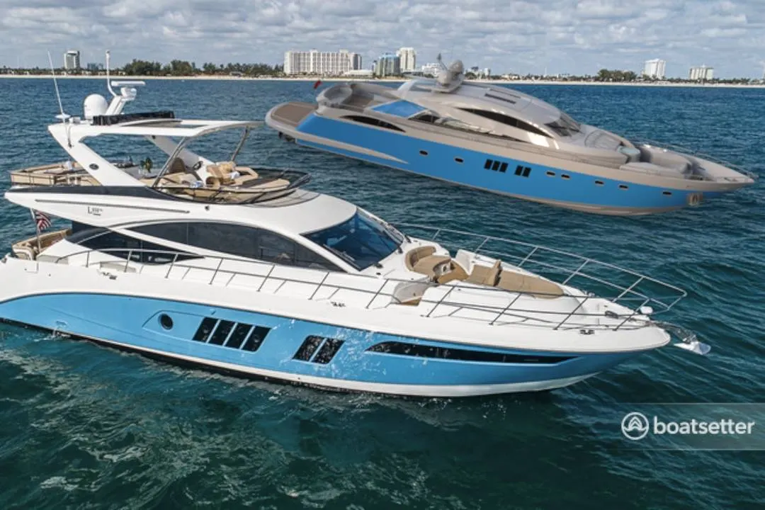
The assembly has been imported to solidworks visualise to create a realistic view. The apperances has been modified here by creating a set environment according to it for making it look realistic.
Hence the final rendering has been done and below were some of the rendered items.
Conclusion:
Hence i conclude that creating a prototype by modelling the individual parts and uniting them as one by using different features in solidworks . In fact modelling in general terms leads to generalising a virtual prototype inorder to modify the parts and understanding the issues occured while assembling instead of solving it on actual part which results in reducing of cost and time.