Advanced Sheet Metal Design Using NX Cad Challenge_2_Box Assembly
DESIGNING OF BOX ASSEMBLY USING NX
Objective:
Using of various sheet metal tools like flanges, tabs, hems,cut-out etc., and understanding the usage of the features addition to the sheet metal for designing the box using NX sheet metal.
Below tools has been used for obtaining the result:
- Tabs
- Normal cut-out
- Bend and unbend
- Flanges
- Breaking corners
- Hems
- Dimples
- Beads
- Mirrors
- Unite
- Closed corners
Description:
- Initially the sheet metal has been made using the tab with given specifications (200mmx150mmx1mm)
- Flanges has been used for creating the side walls of the box with a bend radius of 10mm
- Edges has been made bend by using the bend corner and closed corner tools.
- Using the hem flange tool for creating hem joint which helps in reinforcing the edge, removing the burrs/rough edges
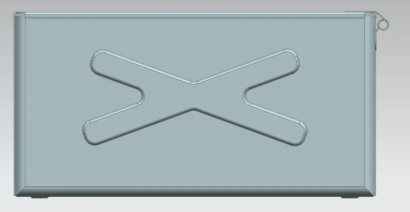
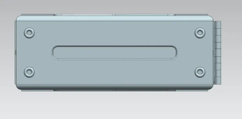
- Dimples and beading has been created for giving stiffness and rigidity to the part by stamping up the sheet of required sketch by using dimple and bead tools
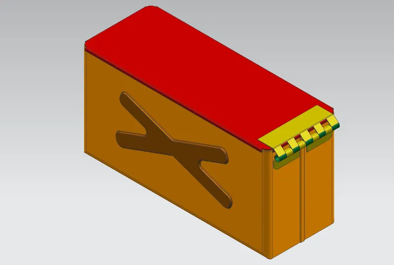
- The body has been mirror into other half and joining them using unite tool for creating a complete base.
- Lid has been created using tab and edges are bent using flange tool
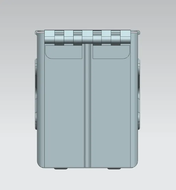
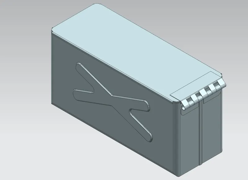
- Finally hinges are created by using the hem tool and flange tool,normal cut-out for movement of Lid.
Views:
Front view:
Side view:
Bottom view:
Isometric view:
Conclusion:
Hence understanding the usage of hem tool, inset types etc.,for obtaining the result and use of various features in sheet metal and effects of addition of features in design stage before going for manufacturing