Photo Realistic Rendering
Photo Realistic Rendering
Objective
The main objective of this project is to obtain sustainable knowledge in SOLIDWORK part modelling, SOLIDWORK assembly and rendering through,
- Modelling each part of the American chopper with proper Dimensions and appearance using the SOLIDWORKS part.
- Assembling all the parts of the American chopper using SOLIDWORK Assembly.
- Doing a Photorealistic render of an American chopper using SOLIDWORKS Photo view.
Introduction
SOLIDWORKS is a solid modeling computer-aided designing (CAD) and computer-aided engineering (CAE) software, widely used for designing in manufacturing industries. Here we are Learning Understanding Solidworks from the base through this project Modeling and Photo Realistic Rendering of American Chopper. First of all, we are dealing with the sketching and Modeling of each part of the American chopper. All the parts created then assembled using solid work assembly, after applying appropriate Decals, Scenes, Environment, Cameras & Lights and then rendering to realistic images using SOLID WORK Add-ins such as SOLIDWORK photo view 360 and SOLIDWORKS Visualize.
American Chopper Designing Procedure: -
- Designing of Components/Parts
- Assembly of Designed Components/Parts
- Applying Decals, Camera set-up & Scenes
- Final Rendering
Designing Approach:

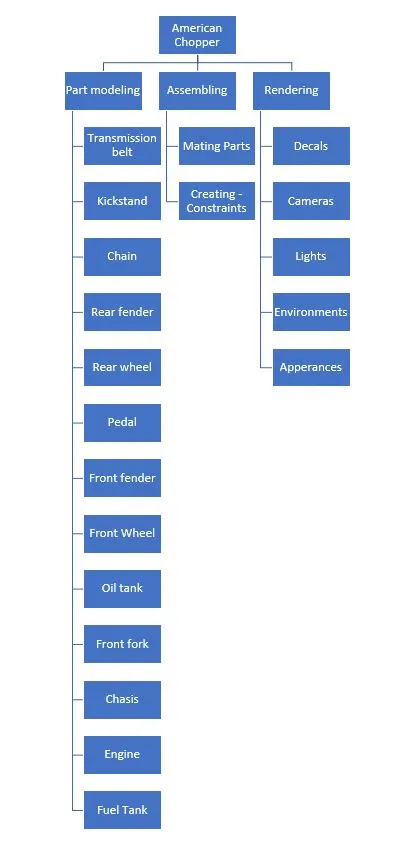
Terminology
These terms appear throughout the SOLIDWORKS software and documentation.
Origin – Appears as two blue arrows and represents the (0, 0, 0) coordinate of the model. When a sketch is active, a sketch origin appears in red and represents the (0, 0, 0) coordinate of the sketch. Dimensions and relations can be added to a model origin, but not to a sketch origin.
Plane – Flat Construction geometry. Planes can be used for adding a 2D sketch, selection view of a model, or a neutral plane in a draft feature.
Axis – Straight line used to create model geometry, feature, or patterns. Axis can be created in different ways, including intersecting two planes. The SOLIDWORKS application creates temporary axes implicitly for every conical or cylindrical face in a model.
Vertex – Point at which two or more lines or edges intersect.
Edge – Location where two or more faces intersect and are joined together. Edges can be selected for sketching and dimensioning.
Face – Boundaries that help define the shape of a model or a surface. A face is a selectable area of a model or surface.
Types of Commands and Their Explanations
Sketch – Create the sketch and decide how to dimension and where to apply relations.
Features – Select the appropriate features, such as extrudes and fillets, determine the best features to apply, and in what order to apply those features must be decided.
Surface – Surface is a type of geometry that can be used to create solid features.
Assembly – Select the components to mate and the types of mates to apply.
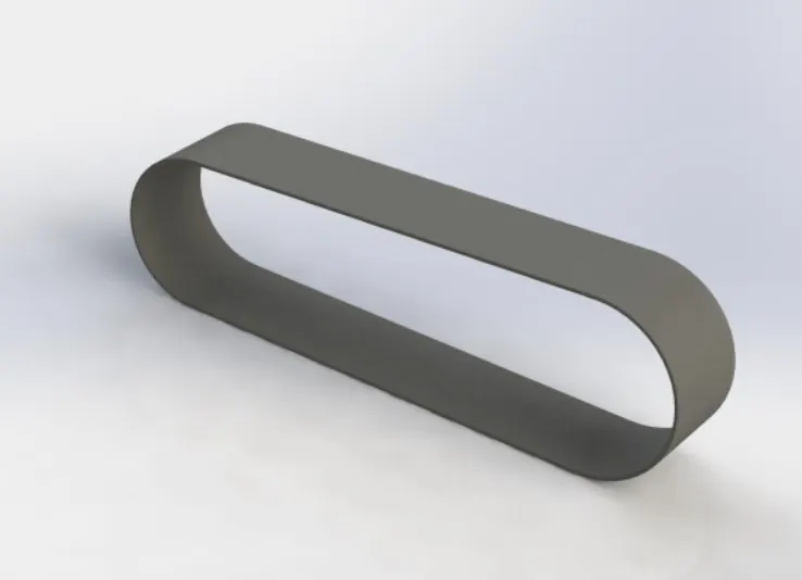
1) Transmission Belt
Commands Used to Model:-
In Sketch
- Line
- Arc
In Features
- Offset
- Extrude
- Fillet
- Appearances
Procedure: -
- Create a new part file, and conform or set a metric unit from the bottom right side corner.
- The front plane was used to create the sketch for the transmission belt.
- Using line command a horizontal line is drawn from the origin to the right and arc, tangent to the line drawn was sketched continuously.
- From the end of the first arc, another line was drawn horizontally towards the left.
- Another arc was drawn to connect both horizontal lines.
- The connecting points of the arcs are made to be tangent to the horizontal lines.
- The starting point was made to be coincident with the origin and required dimensions were applied using the smart dimensions tool.
- Now the sketch was fully defining and then offset the sketch outwards in such a way that it creates a thickness for the transmission belt.
- Then, the sketch was extruded from the sketch plane using the blind option and the required fillets were added along the edges of the belt on both sides.
- Now, the part was saved by adding the matte rubber appearance.
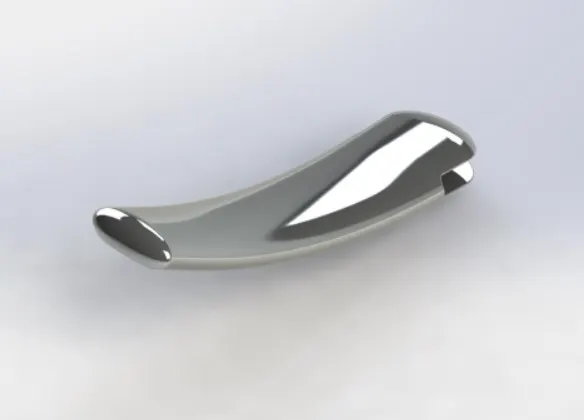
2) Kickstand
Commands Used to Model:-
In Sketch
- Ellipse
- Spline
In Features
- Pierce
- Split
- Lofted Boss / Base
- Extruded cut
- Extruded Boss / Base
Procedure:-
- Create a new part file, and conform or set a metric unit from the bottom right side corner.
- An ellipse was sketched on the front plane and made its center point coincident with its origin.
- Then a spline was created from the origin on the midplane and applied the required dimensions.
- A new plane was generated normal to the spline using a plane tool from reference geometry.
- Using the reference plane another ellipse was sketched and its center point must be pierced with the endpoint of the spline.
- Then by using the Lofted Boss / Base tool a loft was created between the two ellipses and then it was made to align with the spline using centerline parameters.
- Then two domes were created on either side of the lofted model by using the Dome feature for the required dimensions.
- Now on the bottom right side, a rectangular extruded cut was made on the midplane using Extruded Cut with Through All-Both option for making a clamping socket.
- Then a circular holder was extruded in between the clamping socket by sketching a circle on the top plane.
- Then a small portion of the part from the lower side of the kickstand has been split away using a split tool for having a perfect ground clearance.
- The part was saved by adding the fillets for the required edges and applying the chrome plate appearance.
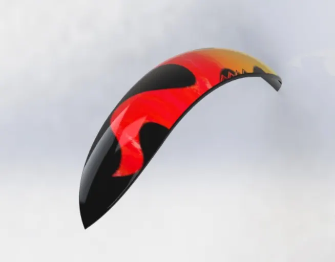
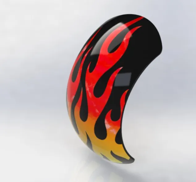
3) Front Fender
Commands Used to Model:-
In Sketch
- 3-Point Arc
- Spline
In Features
- Offset
- Extend Entities
- Trim Entities
- Revolved Boss / Base
- Fillet
Procedure:-
- Create a new part file, and conform or set a metric unit from the bottom right side corner.
- A 3 Point Arc was sketched on the front plane and applied the required dimensions using the smart Dimensions tool.
- Then offset the arc towards inward using the Offset Entities tool and join the two arcs by sketching a line on both sides.
- And the required sketch relations were added for creating revolves using Revolved Boss / Base.
- Then by using the split option the unwanted portion has been removed from both ends and then the fillets were added around the edges to get a smooth edge for the fender.
- Now the part was saved by adding an appropriate appearance.
4) Rear Fender
Commands Used to Model:-
In Sketch
- 3 – Point Arc
- Spline
- Offset Entities
- Extend Entities
- Trim Entities
In Features
- Revolved Boss / Base
- Fillet
- Shell
Procedure:-
- Create a new part file, and conform or set a metric unit from the bottom right side corner.
- A 3 Point Arc was sketched on the front plane and applied the required dimensions using the smart Dimensions tool.
- Then offset the arc towards inward using the Offset Entities tool and join the two arcs by sketching a line on both sides.
- Then a construction line was drawn horizontally from the origin and the required sketch relations were added for creating revolve using Revolved Boss / Base.
- Now for giving a smooth edge for our fender a curve was drawn using spline on the top plane and split the portion which was not required.
- Then shall was created on the inside face of the fender and the fillets were added throughout the edges.
- Now the part was saved by applying an appropriate appearance.
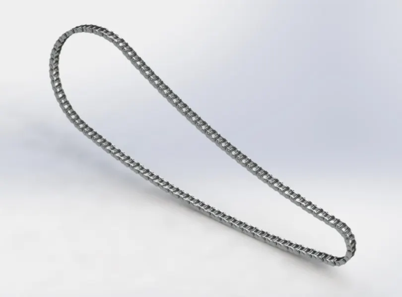
5) Chain
Commands Used to Model:-
In Sketch
- Circle
- 3 Point-Arc
In Features
- Slot
- Block
- Fillet
- Curve Driven Pattern
- Mirror
Procedure:-
- Create a new part file, and conform or set a metric unit from the bottom right side corner.
- The front plane (Midplane chain) is select to create a chain path and with the help of the Construction line and arc command.
- Then the outside chain link and the inside chain link have been sketched on the front plan (Mid plan chain) using the circle, line, and arc commands and saved as a block.
- Both the chain links Insert with the help of insert block command from the tool Menu and extruded Pins and blocks separately as per requirements using Extruded Boss/Base.
- Then by using the Curve Driven Pattern copy the chain links and pins along with the path separately as per requirement.
- The Mirror command is used to mirror the chain links with the help of the Front plane (Midplane chain).
- Now, the part file was saved by adding proper fillets as required and applying the chrome appearance.
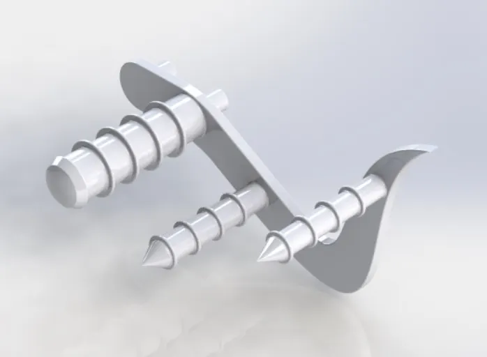
6) Pedal
Commands Used to Model:-
In Sketch
- Lines
- Circles
- Spline
In Features
- Fillet
- Chamfer
- Revolved Boss/Base
- Dome
- Linear Pattern
Procedure:-
- Create a new part file, and conform or set a metric unit from the bottom right side corner.
- The required sketch to model the pedal has been drawn in a front plane and dimensioned it using Lines, arcs, and splines.
- By using a single sketch footrest part was extruded separately as per requirement using Extruded Boss/Base and applied the proper fillets.
- Then the sketch was drawn on the Top plane with the help of the construction line and normal line and the sketch was revolved with respect to the construction line.
- The Dom has been created over the face of the footrest.
- Then the circle extrudes were created using offset, Fillet, chamfer, and Linear pattern options.
- The part was saved by adding a chrome appearance.
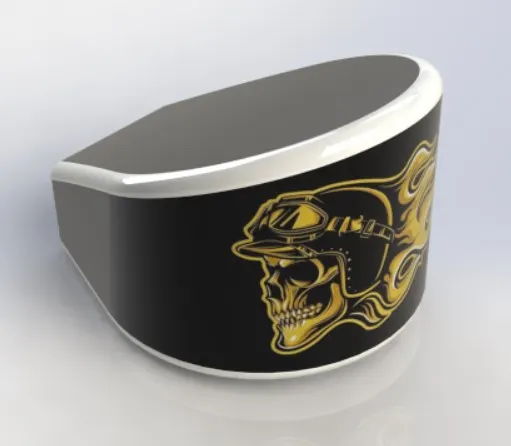
7)Oil Tank
Commands Used to Model:-
In Sketch
- Line
- 3-Point Arc
In Features
- Shell
- Fillet
- Combine
- Extruded Boss/Base
Procedure:-
- Create a new part file, and conform or set a metric unit from the bottom right side corner.
- Select the top plane for sketch and with the help of the construction line, midpoint line and arc desired sketch was created, and extrude it.
- Sketch on the front plane by drawing a spline, line dimension them to make it fully defined, and extrude it by midplane, through all and combine two separated bodies.
- The part was saved by adding the proper fillets along the edges and applying an appropriate appearance.
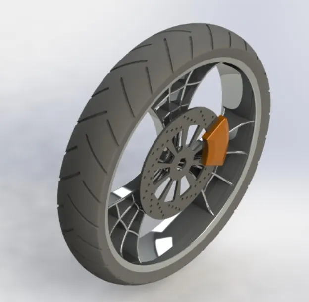
8) Front Wheel
Commands Used to Model:-
In Sketch
- Line
- 3-Point Arc
- Sketch Fillet
- Spline
- Extend Entities
- Trim Entities
- Center Point Rectangle
In Features
- Revolved Boss/Base
- Extruded Cut
- Offset
- Revolved Cut
- Circular Pattern
- Fillet
- Chamfer
Procedure:-
- Create a new part file, and conform or set a metric unit from the bottom right side corner.
- Select the Front Plane and sketch the outer part of the wheel and dimension it to make fully defined.
- Revolve the sketch across the temporary axis.
- Sketch on the right plane, by drawing a vertical construction line from the origin and one more line at an angle. Draw a spline and mirror all three entities across a vertical construction line, extrude them.
- For spider-webbed design, offset all the drawn three entities and remove the unwanted part using cut extrude.
- Connect the spokes using 3 point arcs, offset them and make it a closed sketch by using lines. Extrude the sketch.
- Select the front plane and draw a spline to remove unwanted area using Revolved cut.
- Select the spoke and use a circular pattern. Combine them to make a single solid body.
- For the Rotor sketch on the front plane, by drawing a circle and extruding it, Use a circular pattern to create holes over the rotor, and removed the unwanted portion.
- For Caliper draws a circle and line as per the design of the body. Remove the unwanted area by trimming and extrude it. Apply chamfer and fillets.
- For Tyre Use Rim as convert entities & revolve. Draw rectangles and apply dimensions, relations to make them fully defined. Extrude cut it and apply fillet.
9) Front Fork
Commands Used to Model:-
In Sketch
- Line
- Circle
- Spline
In Features
- Revolved Boss/Base
- Extruded Cut
- Reference Plane
- Reference Axis
- Fillet
- Mirror
- Combine
- Dome
- Linear Pattern
- Swept Boss/Base
- Project Curve
- Body Move
Procedure:-
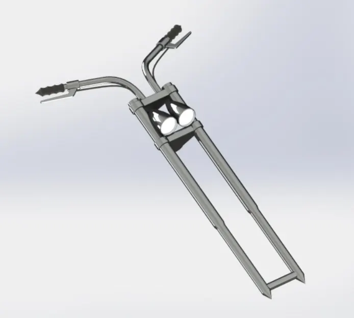
- Create a new part file, and conform or set a metric unit from the bottom right side corner.
- For Fork tube – Sketch on the front plane, by drawing a cylindrical diagram using line and give dimensions, relations to make it fully defined, and then revolve it.
- For Triple Clamps – Select the top plane and draw a concentric circle to the fork tube and draw another circle left and upward. Connect the circles and make them fully defined by giving dimensions, then extrude them.
- For Bulb – Select the front plane, draw a horizontal Construction line, spline, and revolve it. Move the bulb in the Z direction then fillet it.
- For Handle & Brake wires – Select the top plane and draw the handle using spline to make it fully defined. Draw a circle at the end of the spline and sweep along the path.
- Select the bodies Mirror it and combine.
- Give Appearance to the fork to make it realistic.
10) Rear Wheel
Commands Used to Model:-
In Sketch
- Line
- 3-Point Arc
- Sketch Fillet
- Spline
- Extend Entities
- Trim Entities
- Corner Rectangle
- 3-Point Center Rectangle
- Convert Entities
- Intersection Curve
- Linear Sketch Pattern
In Features
- Extruded Boss/Base
- Revolved Boss/Base
- Extruded Cut
- Revolved Cut
- Circular Pattern
- Fillet
- Chamfer
Procedure:-
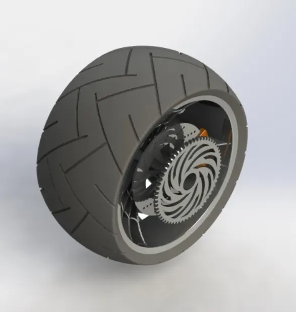
- Create a new part file, and conform or set a metric unit from the bottom right side corner.
- Select the Front Plane and sketch the outer part of the wheel and dimension it to make fully defined.
- Revolve the sketch across the temporary axis.
- Sketch on the right plane, by drawing a vertical construction line from the origin and one more line at an angle. Draw a spline and mirror all three entities across a vertical construction line, extrude them.
- For spider-webbed design, offset all the drawn three entities and remove the unwanted part using cut extrude.
- Connect the spokes using 3 point arcs, offset them and make it a closed sketch by using lines. Extrude the sketch.
- Select the front plane and draw a spline to remove unwanted area using Revolved cut.
- Select the spoke and use a circular pattern. Combine them to make a single solid body.
- For the Rotor sketch on the front plane, by drawing a circle and extruding it, Use a circular pattern to create holes over the rotor, and removed the unwanted portion.
- For a Sprocket Draw a Circle and extrude it. Apply chamfer to the outer part & Create teeth by cut extruded to it. Remove the unwanted portion by using cut extrude & Apply a fillet.
- For Caliper draws a circle and line as per the design of the body. Remove the unwanted area by trimming and extrude it. Apply chamfer and fillets.
- For Tyre Use Rim as convert entities & revolve. Draw rectangles and apply dimensions, relations to make it fully defined. Extrude cut it and apply fillet.
11) Chasis
Commands Used to Model:-
In Sketch
- Sketch Picture
- Spline
- Arc
In Features
- Mirror
- Extruded Boss/Base
- Revolved Boss/Base
- Swept Boss/Base
- Projected Curve
- Reference Geometry
- Extruded Cut
- Chamfer
- Fillet
- Dome
- Split
- Combine
Procedure:-
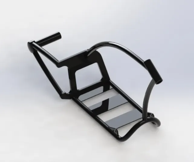
- Create a new part file, and conform or set a metric unit from the bottom right side corner.
- First, the Blueprint was added using the insert Sketch Pictures option on the Mid Plane. The blueprint was used to structure the sketch of the Frame.
- The Bottom Rails for placing the engine were created by drawing a projected curve and the curve was swept using Swept Boss/Base and the other half was mirrored.
- The Back Frame was created using Extrude Boss/Base and Revolved cut. Finally, the required chamfer and fillets were added.
- The Bottom Tail tube was created using Swept Boss/Base and Extruded Boss/Base. The dome option was used to create a dome on the front face of the hub.
- For creating the steer tube Extruded Boss/Base and Extruded cut was used.
- For Creating the foot pedal mounts Extrude Boss/Base, Extrude cut, Mirror and fillet were used.
- Split and combine options were used to group the separate parts of the Frame.
- Finally, the part was saved by adding the chrome appearance.
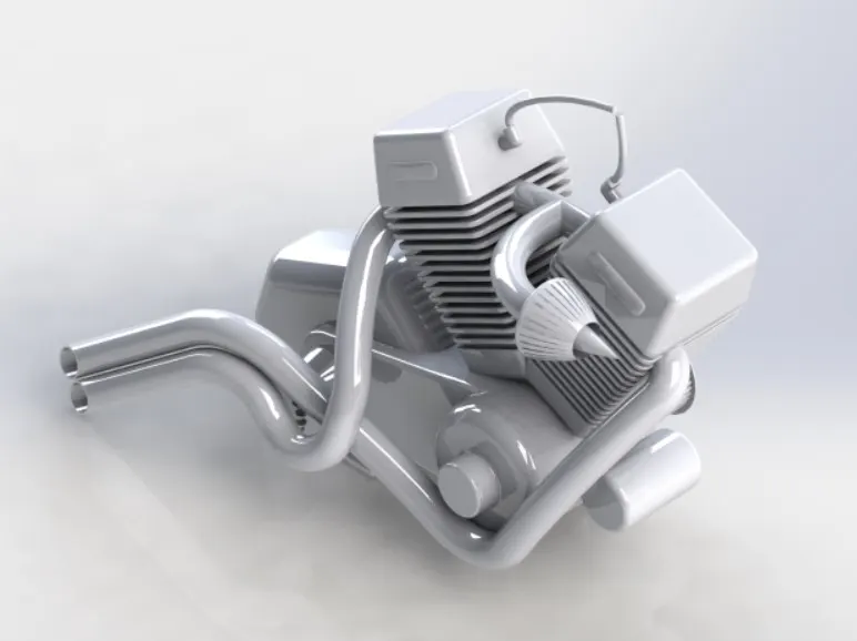
12) Engine
Commands Used to Model:-
In Sketch
- Sketch Pictures
- Line
- Circle
- Arc
In Features
- Composite Curve
- Circular Pattern
- Extruded Boss/Base
- Revolved Boss/Base
- Fillet
- Reference Geometry
- Dome
- Mirror
- Extruded Cut
- Combine
- Split
- Chamfer
Procedure:-
- Create a new part file, and conform or set a metric unit from the bottom right side corner.
- First, the Blueprint was added using the insert Sketch Pictures option on the Mid Plane.
- By using the blueprint the required sketch was drawn and Extruded using Extruded Boss/Base and a proper fillet was applied.
- Then a plane was created using Reference geometry and the transmission system was created for placing the Transmission belt using Revolved Boss/Base, Extruded Boss/Base, Extruded Cut, Chamfer, and Circular Pattern. Then the fillets and dome were applied to the required area.
- For Creating the Cylinders of the engine the Extruded Boss/Base was used and a dome feature was used to create the dome on either side of the cylinder.
- For creating the cooling fins Linear Pattern was used and the other half was mirrored along with the fins and domes.
- The Air Inlet ducts were designed using circular Patterns, Extruded Cut, and Revolved Boss/Base.
- For creating the Exhaust pipes Composite Curve feature was used on the reference plane which needs to be created on the face of the engine cylinder.
- By using Swept Boss/Base the exhaust pipes were created and finally, split options were used to cut the unwanted part.
- Then the spark Plugs were made using Extruded Boss/Base and swept Boss/Base.
- Finally, the part was saved by adding appropriate appearances.
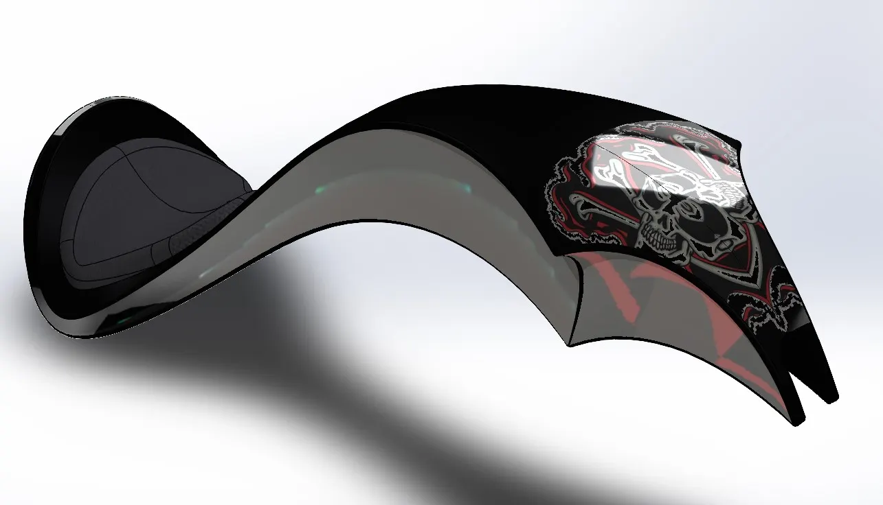
13) Fuel Tank / Gas Tank
Commands Used to Model:-
In Sketch
- Sketch Picture
- Spline
- Arc
In Surfaces
- Extruded Surface
- Swept Surface
- Knit Surface
- Surface Boundary
- Surface Trim
- Lofted Surface
In Features
- Project Curve
- Mirror
- Fillet
- Extruded Cut
- Shell
Procedure:-
- Create a new part file, and conform or set a metric unit from the bottom right side corner.
- Then a plane was created with respect to the front plane and a sketch was drawn and swept using Swept surface Feature and by using the surface trim tool the required shape of the fuel tank was achieved.
- Then by creating another plane a projected curve was drawn and then by using the curve the surface loft was created using the Lofted Surface tool.
- One more plane was created and another curve was projected and Boundary surface tools were used to create a surface of the fuel tank.
- The one half was mirrored and both the halves were joined at an edge by using the Knit surface toolThen Split Line was used to creating the sketch for the seat and the surface Extrude option was used to create the solid body of the seat. Proper fillets were added to get smooth edges for the seat.
- For Placing the fuel tank over the top tube of the Frame a tube-shaped portion was removed using Boundary surface, Lofted surface, Knit Surface, and Swept Cut tools.
- By applying an appropriate appearance the part was saved.
Assembly of American Chopper
Assembly is one of the main features of SOLIDWORK which allows us to assemble the individual parts using an option called assembly mates.
Assembly mates are the geometric relations such as coincident, concentric, parallel, etc. applied between different parts while assembling them. In solid work three types of mates, they are,
Standard mate – They are the common geometric relations such as coincident, concentric, parallel, etc.
Advanced mate – This option allows us to decide the distance between the components, angle between the components, width option, etc.
Mechanical mate – Mechanical mates for components such as Cams, Gears, and Universal joints. Deal with real-world interaction of the components.
Procedure
- Create a new assembly document in solid works. And make sure the unit.
- Using the insert component option insert the chassis as the first component without selecting any option, the chassis itself mate with assembly planes and make sure the plane of the assembly and chassis is the same.
- After that insert all other components and properly mate them with the chassis. Because as we move the chassis make sure all the components move along with the chassis. Applied proper mates, dimension, and relation with chassis and float the chassis and move it to make sure all the components move with chassis.
- The Front wheel mates with the front fork and make sure as the fork rotates the wheel also rotates along the fork.
- After that make sure both the wheels and stand to touch the ground level. And applied the appropriate mate with the chassis top plane.
- And after inserting all the components and applying proper mates save the assembly.
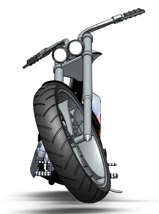
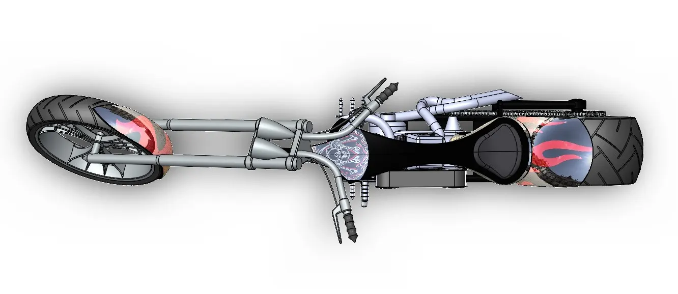
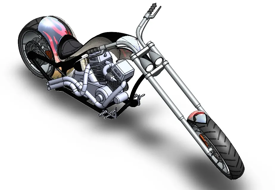
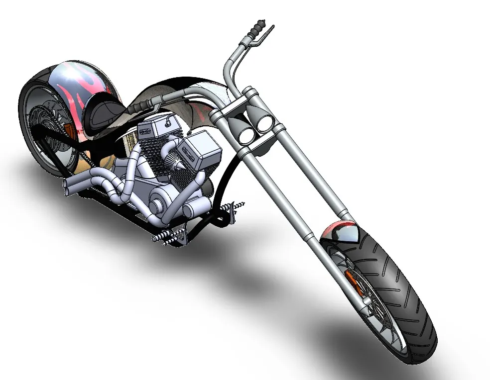
The different views of the assembled chopper are given below:-
Front View
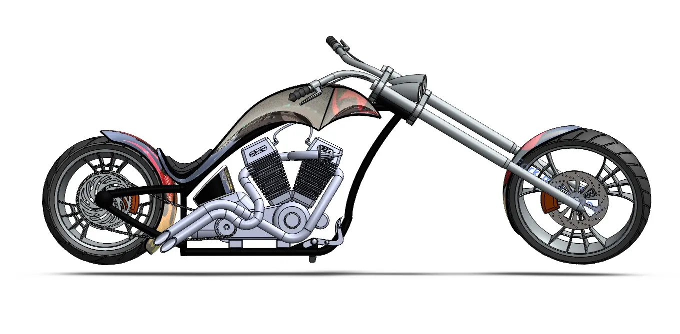
Right side View
Top View
Isometric View
Camera View
Rendering of American Chopper
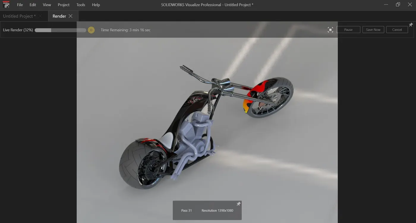
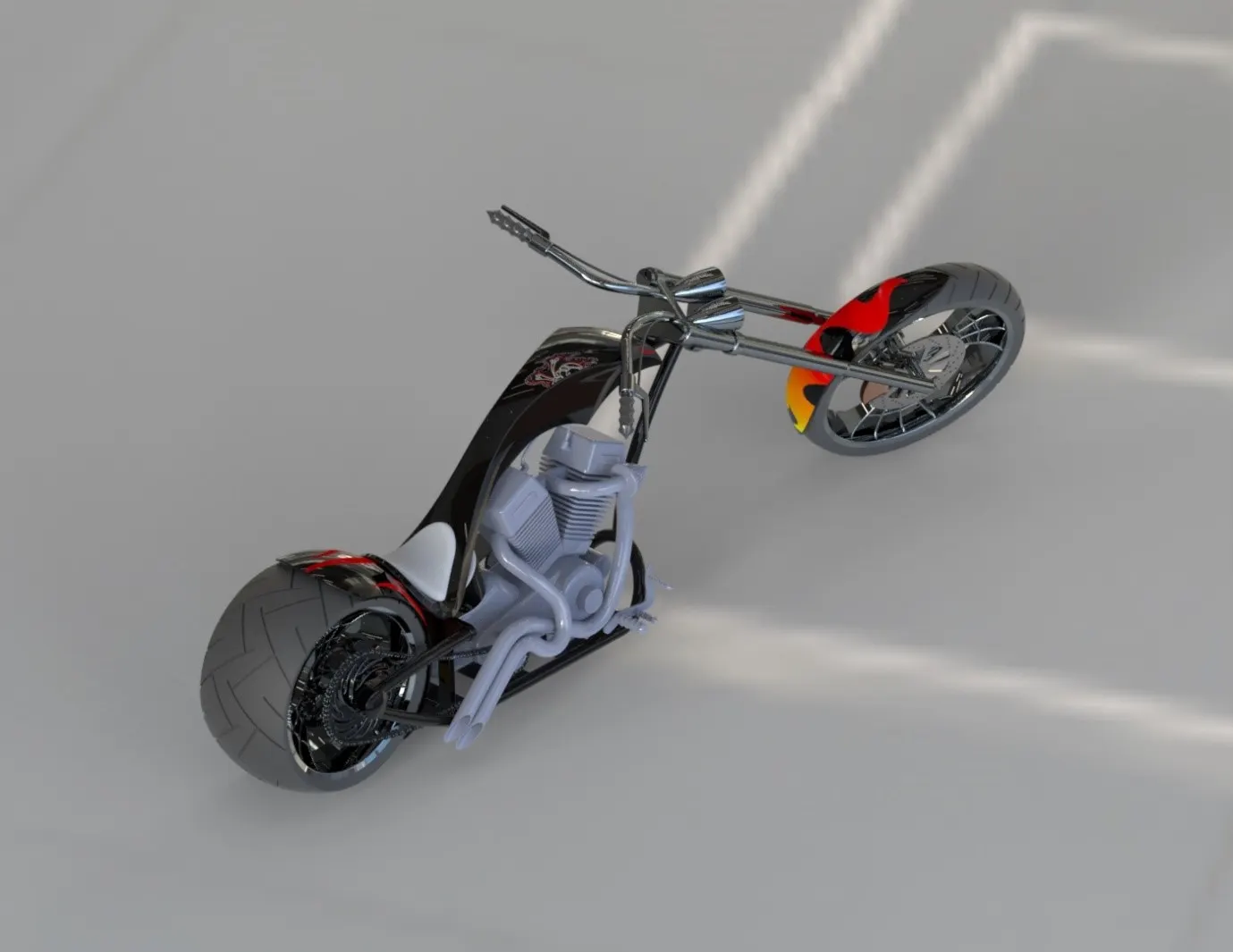
Rendering is the process of creating a Hyper-Realistic image of the components/Assembly. Here we are using SOLIDWORK add-ins as SOLIDWORK Photo view 360 and SOLIDWORK Visualize to render our assembly.
PhotoView360 – PhotoView 360 produces photo-realistic renderings of SOLIDWORKS models. The rendered image incorporates the appearances, lighting, scene, and decals included with the model.
Solidworks Visualize – SOLIDWORKS Visualize allows us to leverage our 3D CAD data to create photo-quality content in the fastest and easiest way we can from images to animations, interactive web content, and immersive Virtual Reality. SOLIDWORKS Visualize is the Camera for our CAD data.
Before the final render, we have options such as adding.
Decals – Decals are the graphics that we can wrap on a solid body. For example Adding stickers to the fuel tank, oil tank, etc.
Camera – Using the camera option we can set up a camera view and save that view.
Scene – The option to set up a scene, Environment, and background.
Lights – Using the light option we can add lights to the model. Types of lights in SOLIDWORKS are Directional light, Point light, Spotlight, sunlight.
Procedure for Photo View 360
For each Solidworks model to be rendered, the process required the same steps. Most of the steps are done within Solidworks with only a few steps requiring Photo view 360.
The following steps are required until a satisfactory output is obtained: -
Position the Model – Use a standard view, or use zoom, rotate, and move to position the model in the desired position.
Apply appearance to the model, feature, and/or selected faces.
Set the Scene – Select one of the various present scenes, or set your own background and scenery.
Set Lighting- Adjust the environmental lighting or add direct lights. Preview Render the preview is a test of the settings before the final render.
Render the Model – The model is rendered to the final render window.
Save Output – To be used, the final render must be saved as a separate image file.
Post Processing – The rendered image output is not always the final product. Often the image output is used with other programs for additional effects.
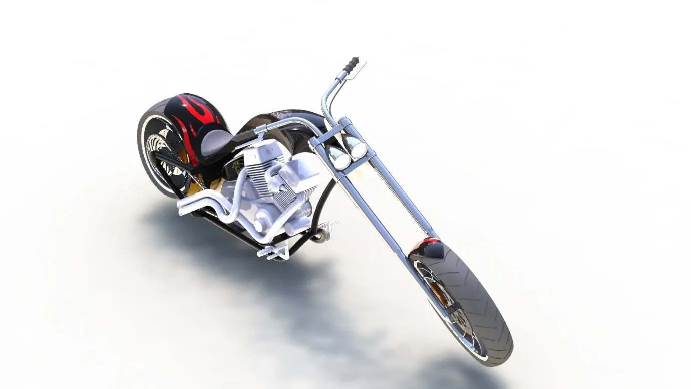
Procedure for Creating Visualization
- Create a new project by importing the required assembly or models into the Solidworks Visualize.
- Add the required appearance, environments, backplates, and lights.
- By using the camera tool position the designed model in realistic view.
- Make sure that the model touched the floor. It can be achieved by using the snap the floor option on models.
- By applying the required setting the required output can be rendered using the output tool.
Conclusion
All the components are created with proper dimensional and geometric constraints and I have made a better knowledge in part modeling.
Assembly of the American chopper has done successfully and learned almost every tool and feature in solid works assembly.
Hyper-realistic images are rendered out and I acquired immense knowledge in using Solidwork Photoview 360 and Solidwork Visualize.
Google drive Link: https://drive.google.com/file/d/1HBvZxTeBrK28pOqb7QAjqony0o_XpRe5/view?usp=sharing