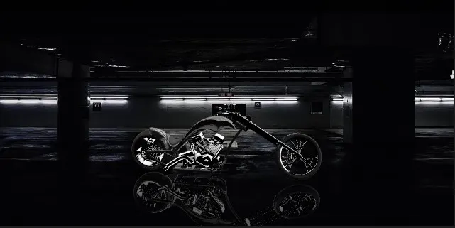
Photo Realistic Rendering
INTRODUCTION
In this project we learn about the American Chopper bike Design and Assembly with the help of Solidworks 2022. In this first we learn commands after that using this commands we draw the sketch of part with the accurate dimension. After completing all part we assemble the American chopper. Then we add the lights, camera, decal to the model and do the rendering of chopper using the solidworks visualization 2022.
Part Of American chopper
- Transmission belt
- Kickstand
- Front and rear fender
- Oil tank and pedal
- Chain
- Front and rear wheel
- Front fork
- Chassis
- Engine
- Gas Tank
Design approach
There is two type of design approach
- Bottom up approach
- Top down approach
Bottom-up Design
Bottom-up design is the traditional method. You first design and model parts, then insert them into an assembly and use mates to position the parts. To change the parts, you must edit them individually. These changes are then seen in the assembly.
Top down approach
In Top-down design, parts' shapes, sizes, and locations can be designed in the assembly
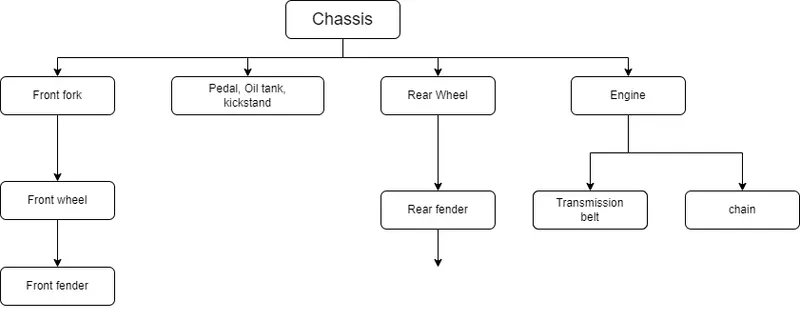
Flowchart
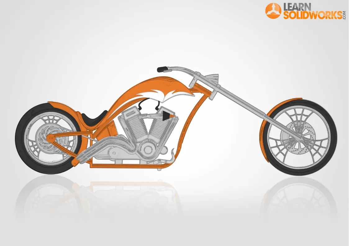
BLUEPRINT
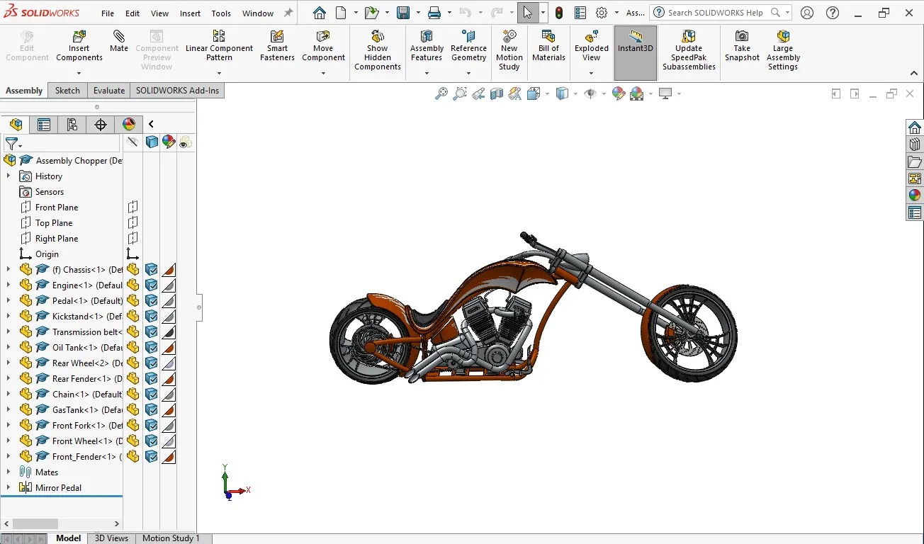
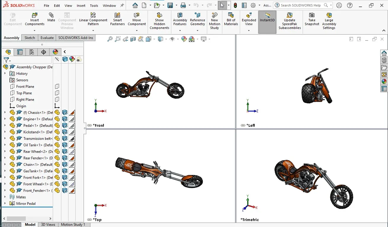
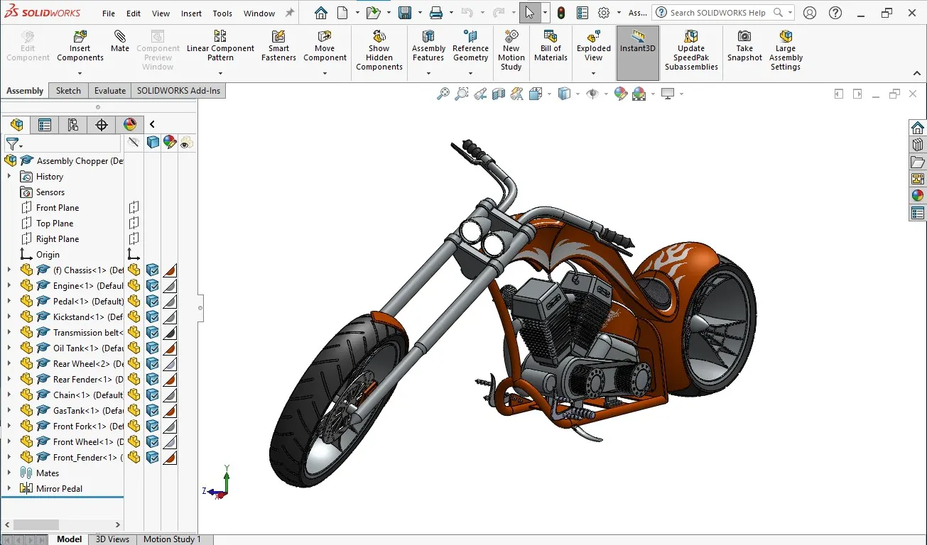
Assembly of the Chopper
A new assembly was created in the solidworks and the first component to be imported was the chassis. it was placed at the origin by simply selecting the ok button without positioning it.
The next component inserted to the assembly was the engine.
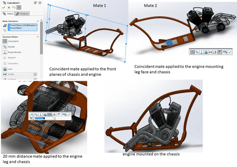
Fig 1.1: Mounting of engine on the chassis
The next component inserted to the assembly was the pedal. Three mates were applied to the part as shown in the attached figure to fully constrain its rotation and translation.
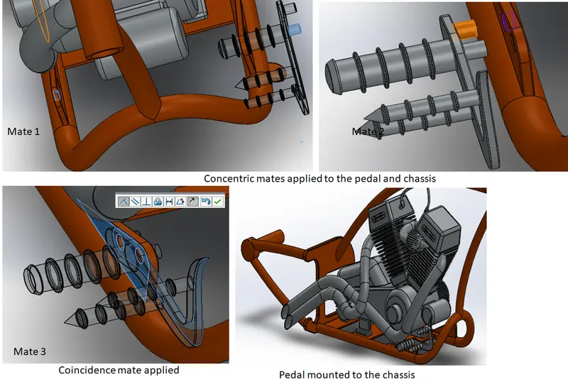
Fig 1.2: The mounting of pedal to the chassis
Next, a mirrored component of the pedal was created for the other side of the bike. This was done inside of the assembly itself and LH was added to it as suffix for identification purpose. the attached figure shows details for the same.
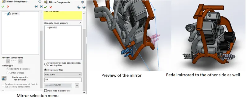
Fig 1.3: The mirror of the pedal obtained
The next component inserted to the assembly was the kick stand. Three mates as shown in the attached figure were applied to it. The limit angle mate available under the advanced mate options was used to permit the rotation of the kickstand.
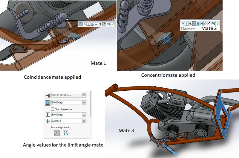
Fig 1.4: the mates applied to the kickstand
The next part added to the assembly was the transmission belt. Width, concentric and angle mates were applied to position it properly in the assembly. The attached figure shows details for the same.
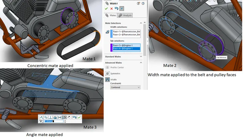
Fig 1.5: The mates applied to the belt.
The next part added to the assembly was the oil tank. Three mates were applied to it as shown in the attached figure.
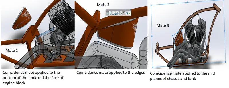
Fig 1.6: The mates applied to the oil tank
Next component added to the assembly was the rear fender. Mates applied to fix it are shown in the attached figure.
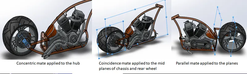
Fig 1.7: The mates applied to fix the rear wheel with the frame.
The next component added to the assembly was the rear fender. The mates applied to fux it to the assembly are shown in the attached figure.
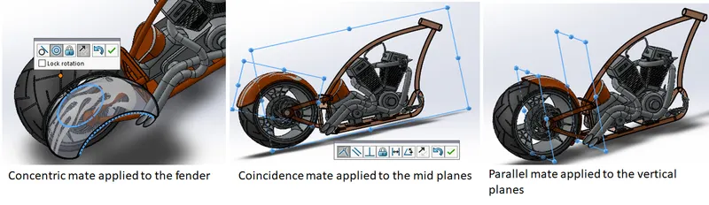
Fig 1.8: The mates applied to attach rear fender to the assembly
After that the chain was added to the assembly. The mates applied to position the chain properly are shown in the attached figure.
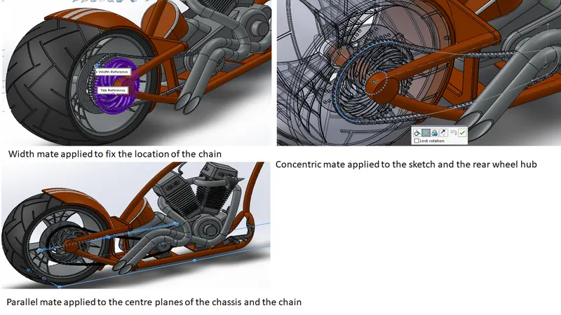
Fig 1.9: The mates applied to the chain
The next component inserted into the assembly was the fuel tank. Mates applied to position it are shown in the attached figure.
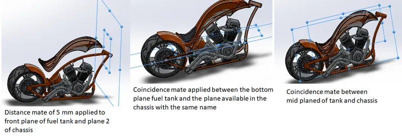
Fig 1.10: The mates applied to the fuel tank
After that front fork was added to the assembly. Attached figure shows the mates applied to the front fork and chassis.
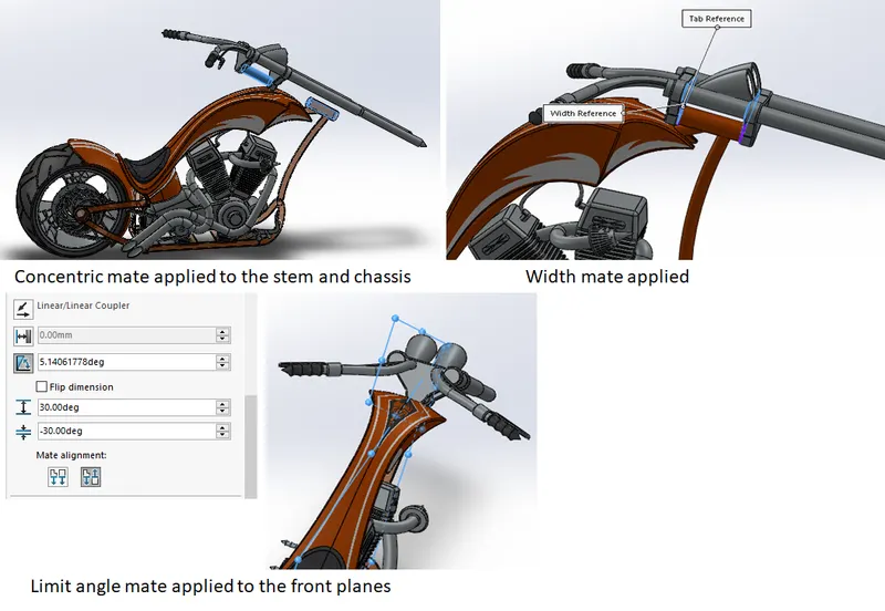
Fig 1.11: The mates applied to constrain the front fork
The next part added to the assembly was the front wheel. A plane in the middle of the front fork was created to mate the front wheel properly. The details are shown in the attached figure.
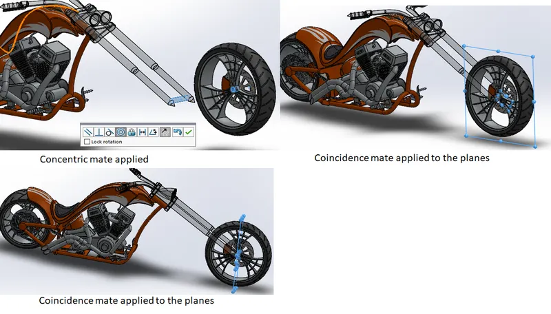
Fig 1.12: Mates applied to the front wheel
The final component inserted into the assembly was the front fender. Mates applied to constrain it are shown in the attached figure.
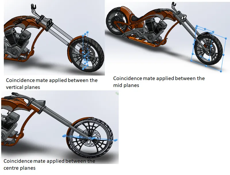
Fig 1.13: Mates applied to constrain the front fender.
Rendering of the chopper
First of all a tangent relation was added between the tyres and the top plane to make the bike appearing touching the ground. A similar mate was applied between the kickstand and the top plane to make the bike appear being parked.
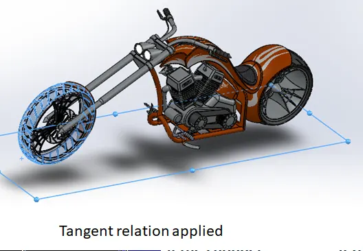
Fig 1.1: The tangent relation applied to front wheel and the top plane.
Then rendering was done in the Solidworks Visualise. With the limited processing power available, higher number of passes could not be applied. Some of the render images Was created in photoview360 available inside solidworks by using Edit scene and scheduling render(keeping render in background by setting time). Some of the rendered images are attached below.
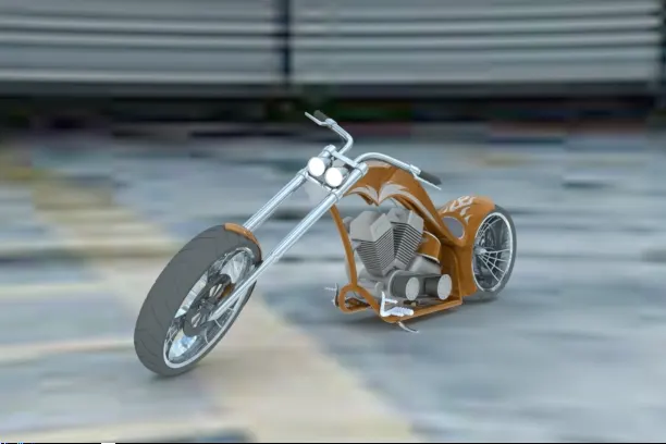
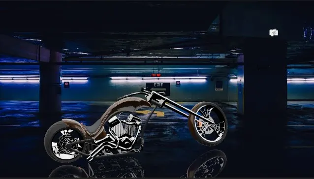
Fig 1.2: The rendered image using back plate in Solidworks visualize.
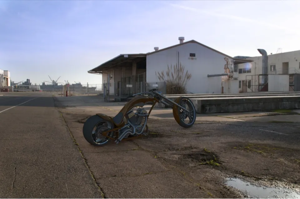
Fig 1.3: The rendered image using Environment option in edit scene command