Photo Realistic Rendering
American Chopper Modelling Using SolidWorks
Objective:-
- To create models for different parts of an American Chopper.
- Assembly of the AmericanChopper.
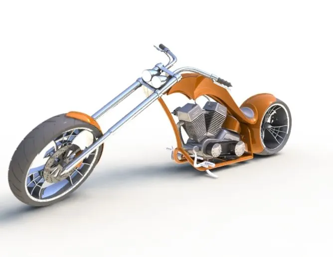
- Create a photorealistic model and render the model of the Chopper using Solidworks Photoview 360.
Methodology:-
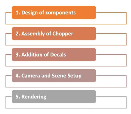
Part which is created for American Chopper :
The following part of the chopper is modelled by Solidworks and assembled them.
- Transmission Belt
- Kickstand
- Front Fender
- Rear fender
- Oil Tank
- Chain
- Pedal
- Front Wheel
- Rear Wheel
- Front Fork
- Chassis
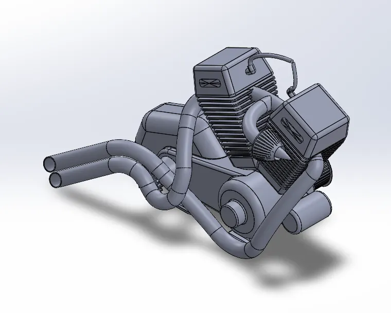
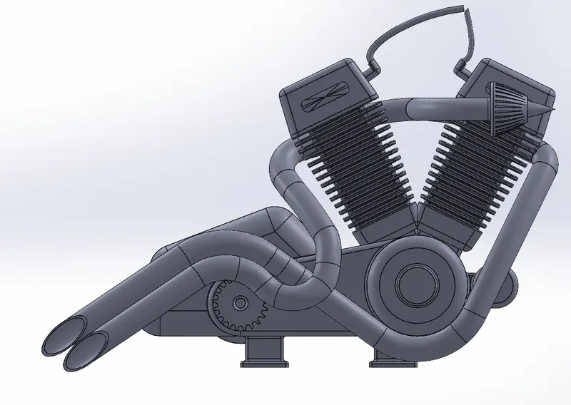
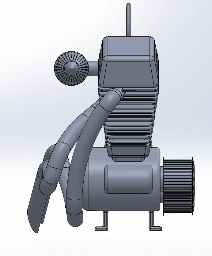
- Engine
- Gas Tank
Now let us see the every part in detail.
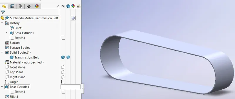
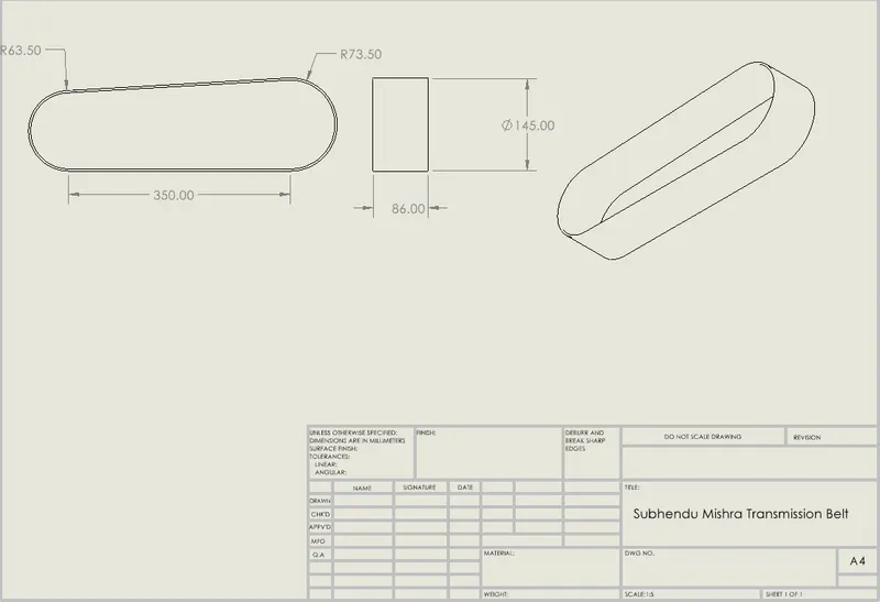
TRANSMISSION BELT
Main features: Boss extrude, fillet and offset entities.
Procedure:
- Create a new part using customized template.
- Selecting the front plane, sketching the profile of the transmission belt.
- Draw a line horizontal to the origin and by hovering the mouse over the end point create an arc tangent to that line.
- Draw another line tangent to the arc.
- Create an arc tangent to the line on the other end as well.
- Give tangency relation betweeen the both the arc and the lines.
- Give the appropriate dimensions and relations to fully define it.
- Now using the offset entities tool, offset the profile outwards.
- Exit sketch.
- Using extruded boss/base option, exturde the skecth with required dimensions with blind option.
- Apply fillet on the edges using the face for selection with required radius, which collects all the external edges with tangency.
- Save the part.
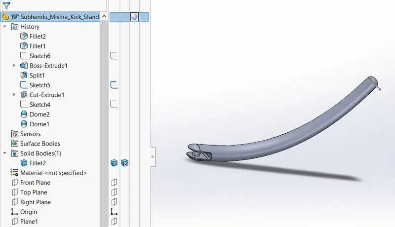
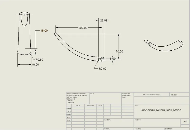
KICK STAND
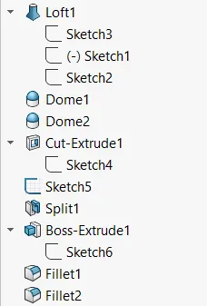
Main features: Reference plane, pierce relation, lofted boss/base, dome, extrude cut and split.
Procedure:
- Create new part using customized template.
- Sketch an ellipse with appropriate dimensions and relations on the front plane.
- In the mid plane, sketch a spline from the origin to the top left corner by giving the required horizontal and vertical dimensions.
- Using spline handle control the direction and the tangency and the give the relation as horizontal.
- By using Features->Reference geometry->plane, create a reference plane selecting the spline and the end point. This creates a plane normal to the spline coincident to the selected point.
- On the created plane, draw a new ellipse with required dimensions and relations.
- Using pierce relation, intersect the spline and the newly created ellipse.
- Exit sketch.
- Using lofted boss/base features, select both the ellipse as the profiles and spline as the centre line parameter for the direction of the loft, creating the solid shape of the kickstand.
- Using the dome tool in the features create an elliptical dome on the either ends.
- In the sketch mode on the mid plane draw a rectangle at the origin with the required dimensions.
- Using the extrude cut option with the rectangle as the profile make an extruded cut with through all condition.
- On the created reference plane, draw a mid-point line at the appropriate distance from the origin
- Using split option cut the base part which is required to be a flat base for the kickstand to stand on the ground.
- Using top plane sketch a circle at the origin with required dimensions.
- Using extruded boss/base with upto next condition create an extrude on both the sides.
- Using the fillet tool create the fillet at the required edges with varying dimensions.
- Save the part.
FRONT FENDER
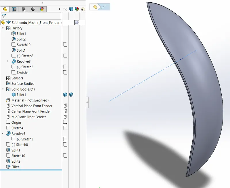
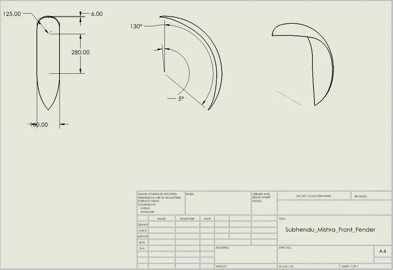
Main features: Revolve and split.
Procedure:
- Create a new part using customized template and the change the names of the planes as required.
- Selecting the vertical plane, using 3 point arc, offset entity, line, trim and extend entities options,create the profile for to revolve the part.
- Draw a construction line on the centre plane as the axis for revolution.
- Using the revolve boss/Base, and the appropriate angles of revolution on the both direction create the basic front fender.
- Now on the centre plane in the sketch mode, draw a construction line at the origin. Using the dynamic mirror option create a spline with required dimensions as profile to use for splitting the end of the front fender.
- Use the same procedure to split rear end as well.
- Apply fillet along the upper surface of the part.
- Save the part.
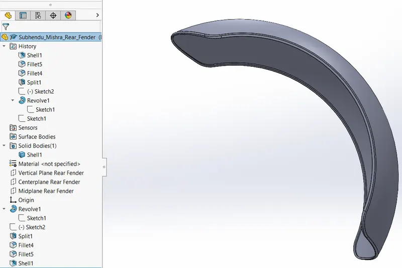
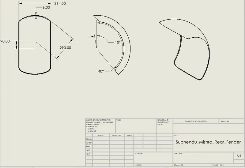
REAR FENDER
Main features: Shell and split.
Procedure:
- Create new part using customized template.
- Rename the planes as required.
- On the vertical plane create a sketch profile to revolve using the 3 point arc, lines, offset, trim and extend entities options with appropriate dimensions and relations.
- Revolve the sketch with required angles in both the directions.
- On the centre plane sketch a profile using the 3 point arc to cut the leading edge of the fender using split.
- Now apply fillets on the four corners of the fender and the edges of the top surface as well.
- Selecting the inside surface make a shell with required dimensions.
- Save the part.
OIL TANK
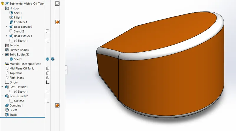
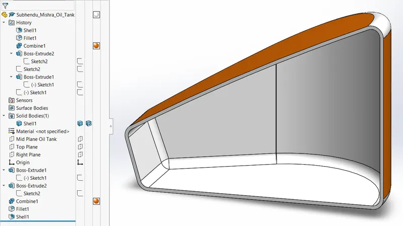
Main features: Combine feature and shell.
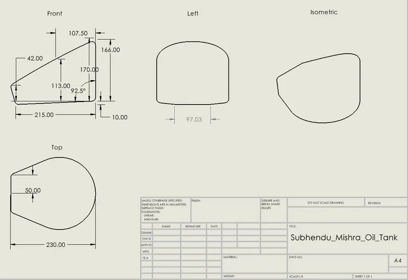
- A 2D Sketch is created as per the given the dimension in the top plane.
- The sketch is then extruded on both directions 170mm in one direction and 10mm in other.
- A new sketch is created on the midplane( front) and extruded into both the directions using through all option.
- Combine feature is used to build a common part using both the models.
- Fillets are applied at the edges and shell feature is applied with thickness 3mm and previewed using cut section to ensure that shell is applied.
- Appearance of the oil tank is changed to sienna with white at the edges.
- Part is saved.
CHAIN
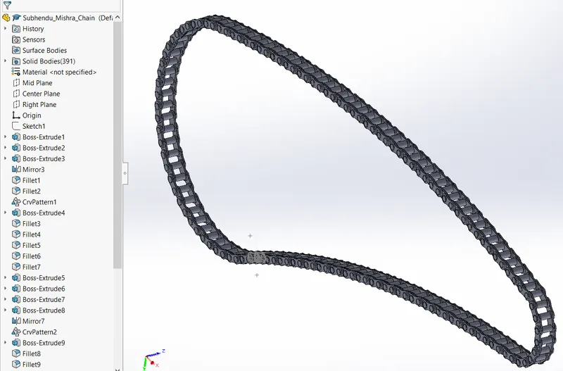
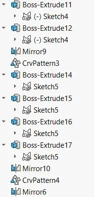
Main features: Curve driven pattern and mirror.
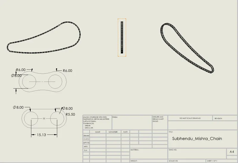
- After renaming the planes sketch is created at the midplane according to given dimensions.
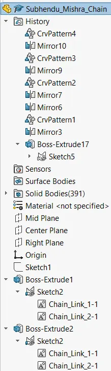
- A runaway sketch is created at the midplane and blocks are creates, namely as chain_link1 and chain_link2, in order to save them as a separate part and use them to create the links.
- The blocks are inserted on to the 2D sketch created on the midplane and applied certain relations to make coincident with the curve .
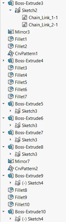
- The blocks are then extruded and fillets are applied at the faces of the pin.
- Curve driven pattern is applied along the curve and some extrudes are drawn manually to perfectly align with the chainpath.
- Later the solid bodies are classified into chain plates and pins in separate folders to keep them more organized and the chain plates are mirrored using mirror entity.
- Chrome Appearance is applied to the chain.
- Part is saved.
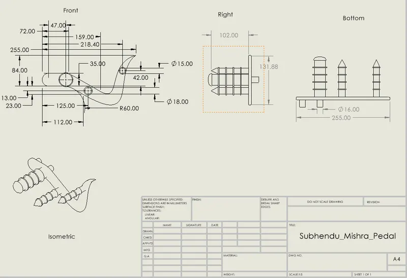
PEDAL
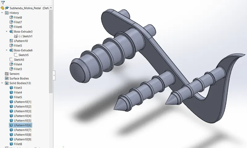
Main features: Linear pattern, revolve, chamfer and dome.
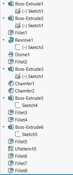
- 2D sketch is created at the front plane as per given dimensions and extruded using etruded boss/base upto 8mm.
- A new sketch is created on the front face of the model and extruded upto 20mm.
- Another sketch is created on the other face of the model and is revolved using revolved boss/base feature.
- Dome feature is applied at the end face of the revolved part.
- Unsymmetrical chamfer is applied to other two parts.
- A new sketch is created by using offset entities option at the base of the three parts and is extruded from the face at an offset of 20mm of 2.5mm.
- Fillets are applied to the newly created extruded parts and linear pattern is applied to create four instances of the same at a spacing of 20mm.
- Fillets are applied to the remaining edges of the model.
- Part is saved.
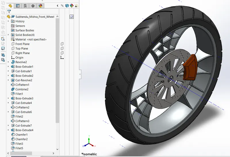
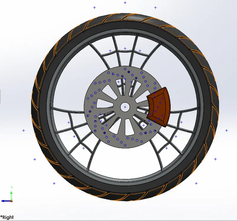
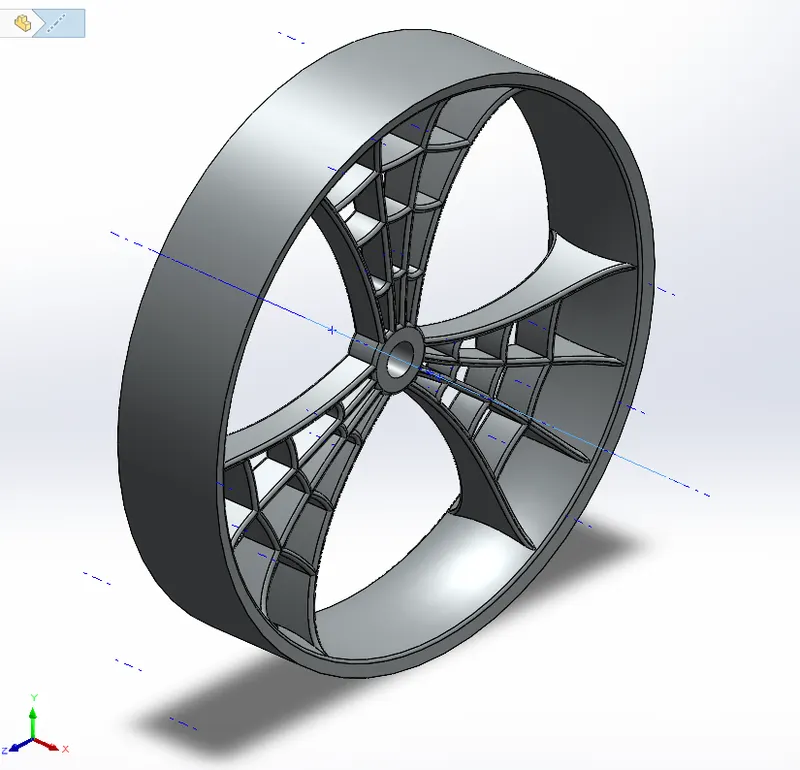
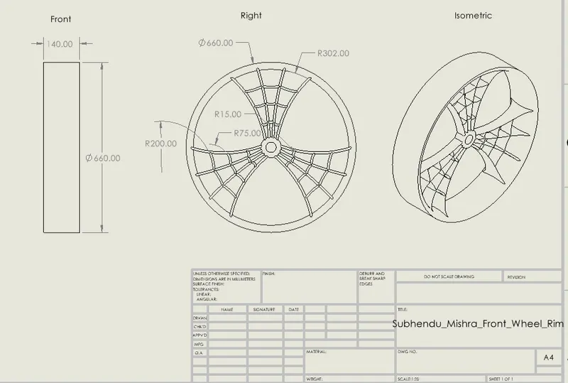
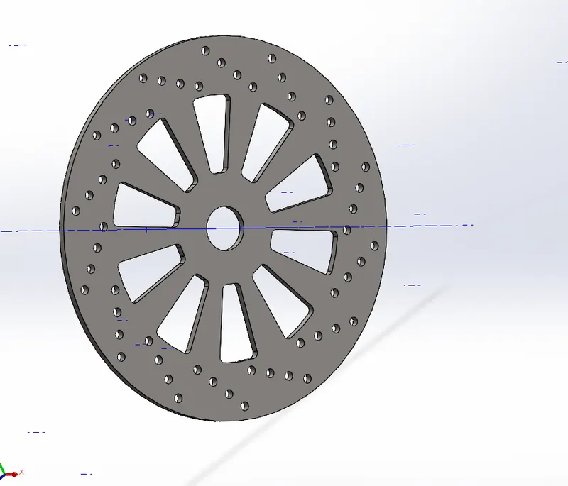
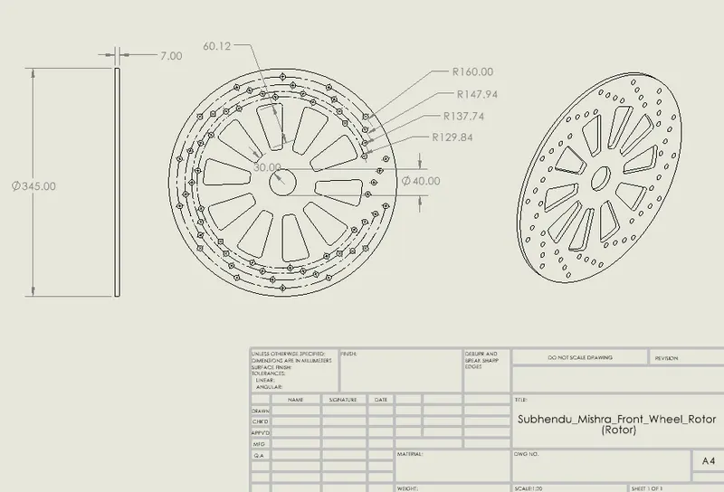
FRONT WHEEL
Front wheel has the following parts:
- RIM OF WHEEL
-BRAKE ROTOR
- CALLIPER
- TIRE
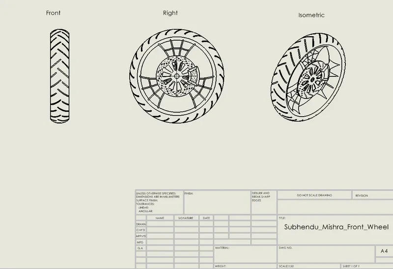
Front Plane -
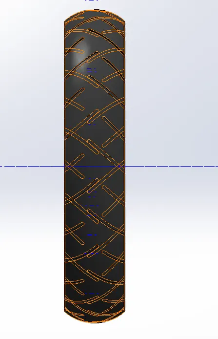
Right Plane -
Feature Tree -
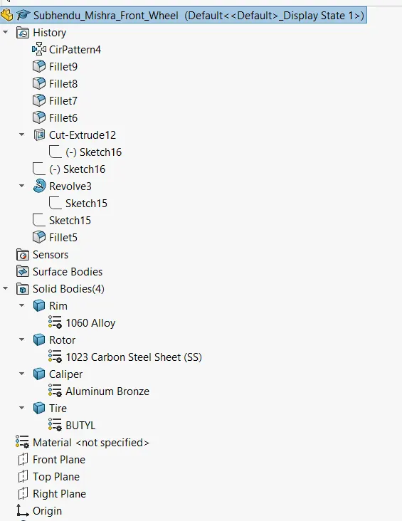
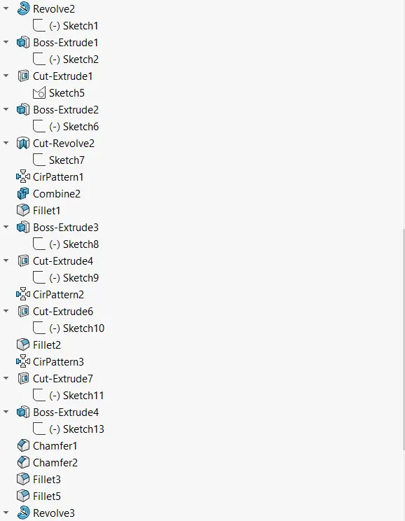
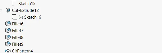
1. Rim
2. Rotor
3. Caliper
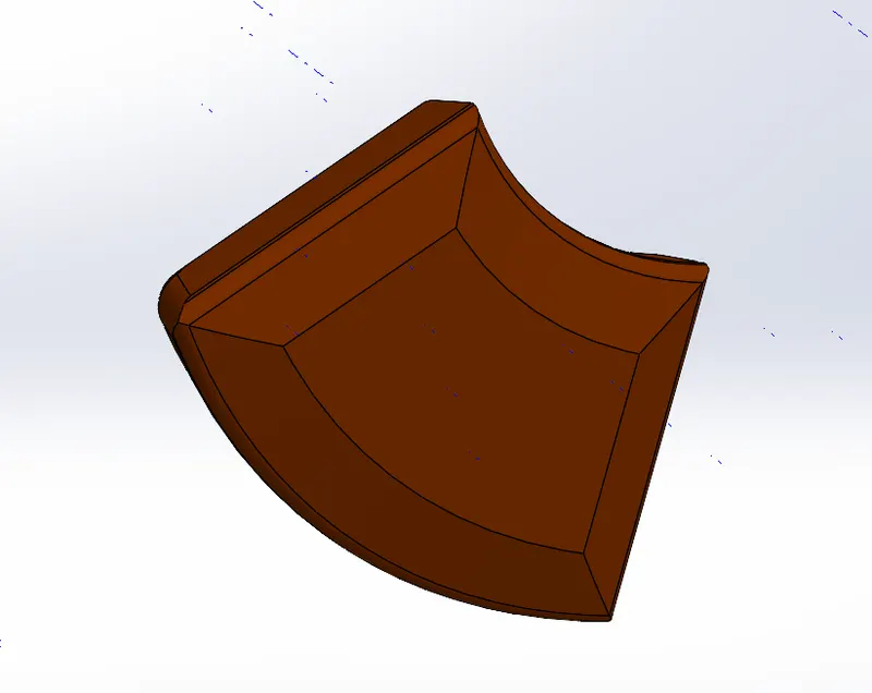
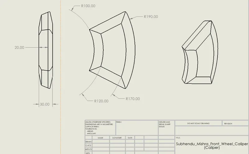
4. Tire
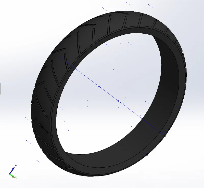
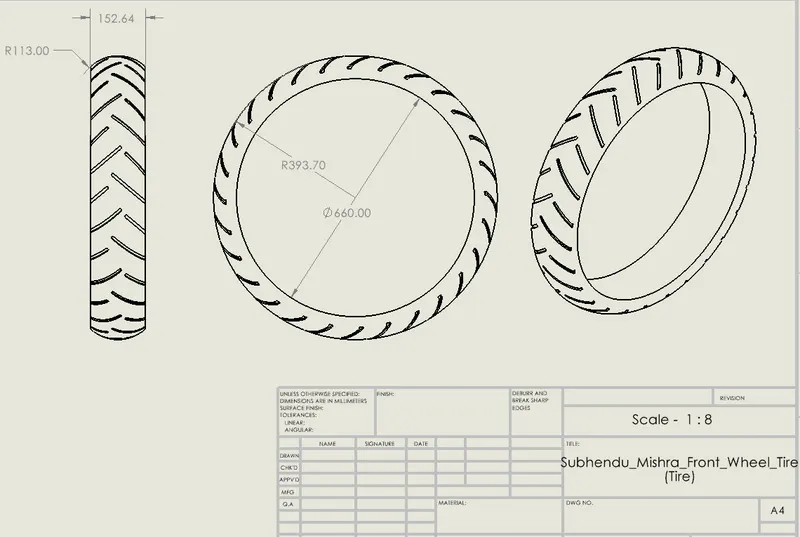
REAR WHEEL
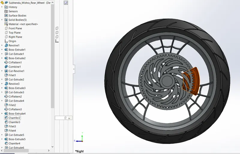
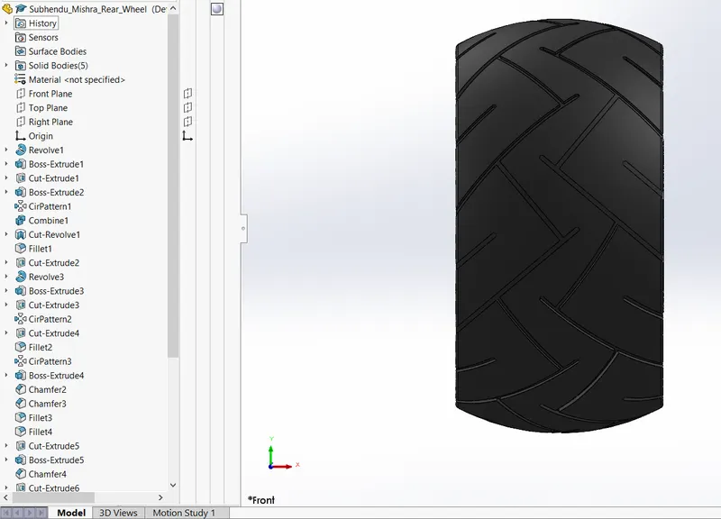
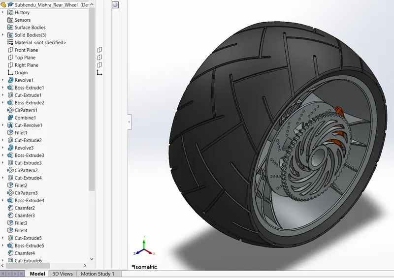
Rear Wheel Feature Tree :
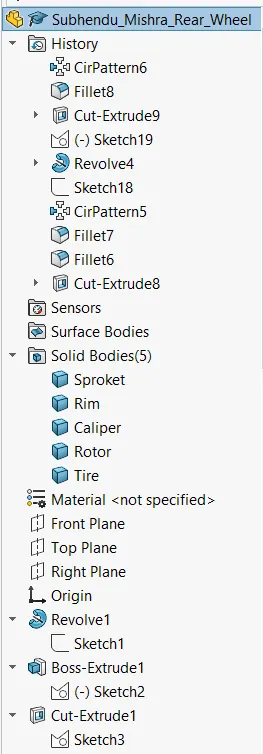
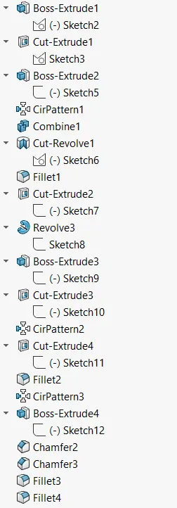
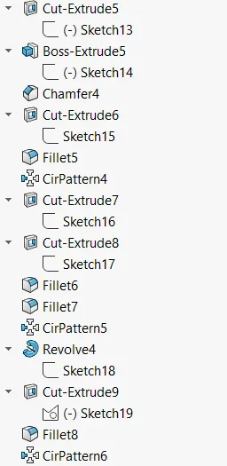
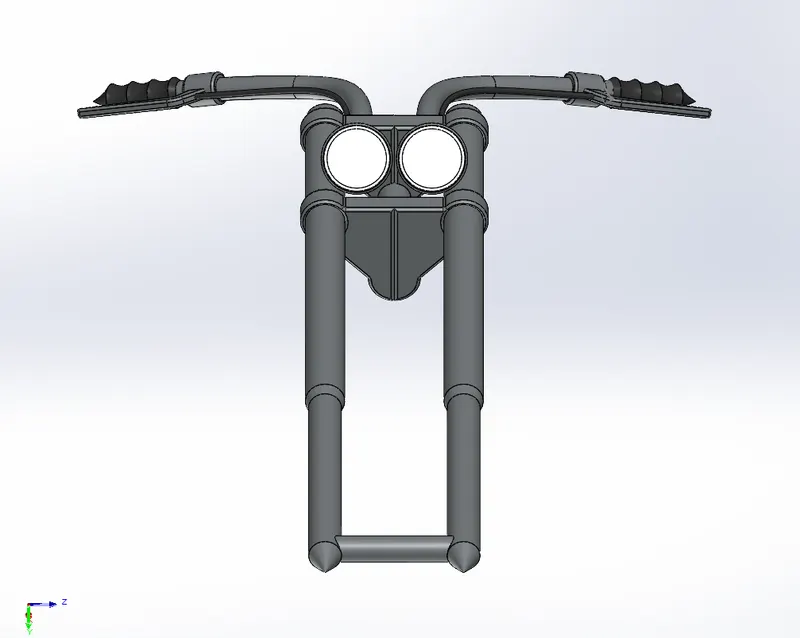
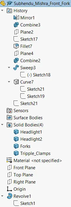
FRONT FORK
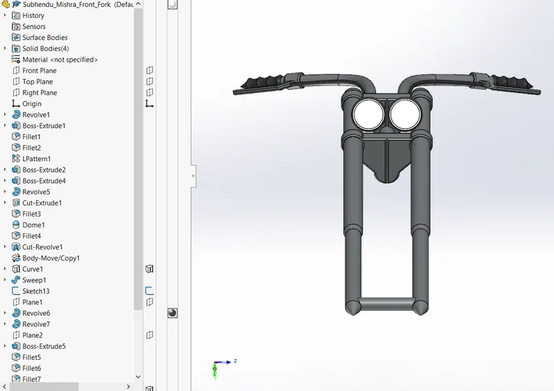
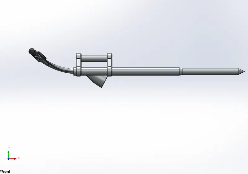
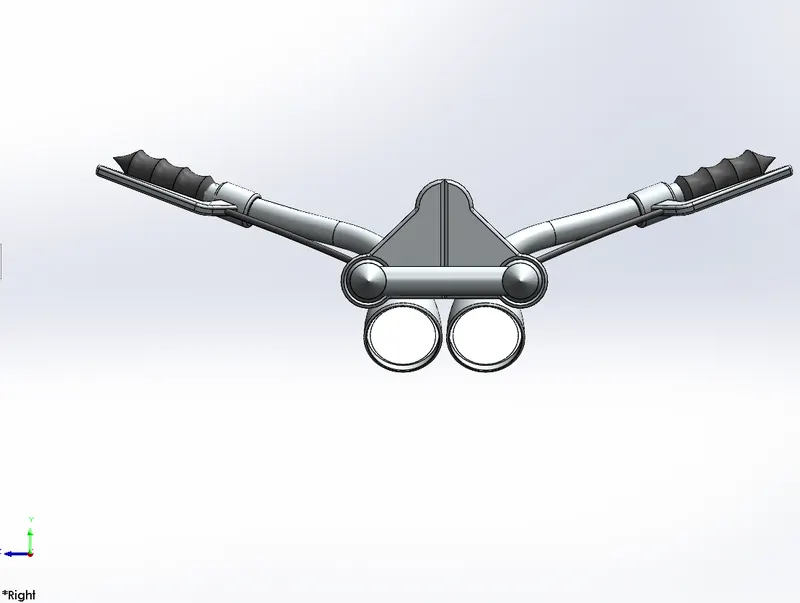
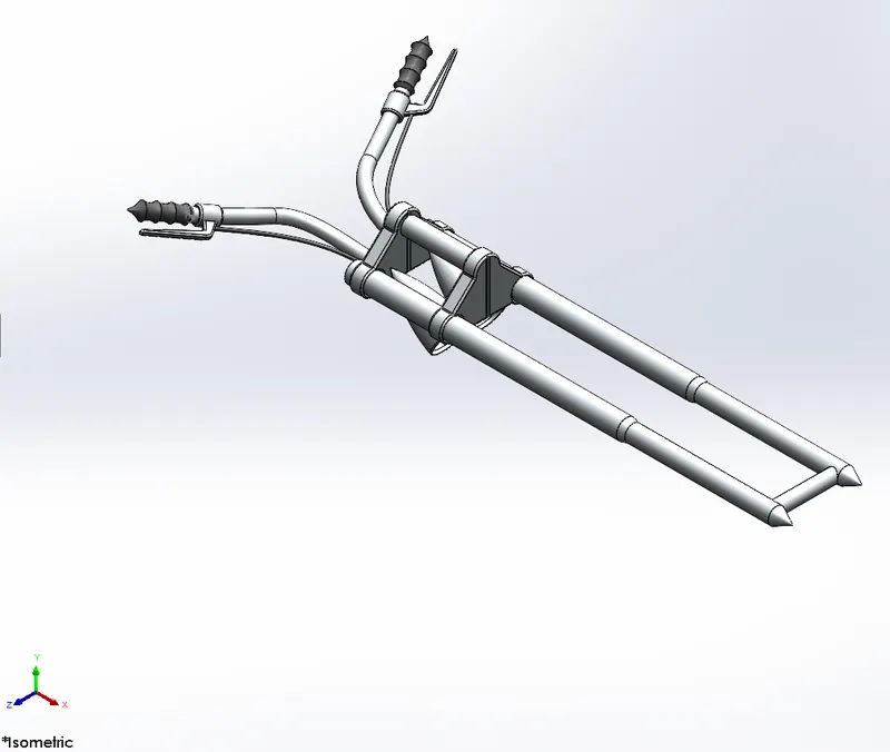
Front of the Bike :
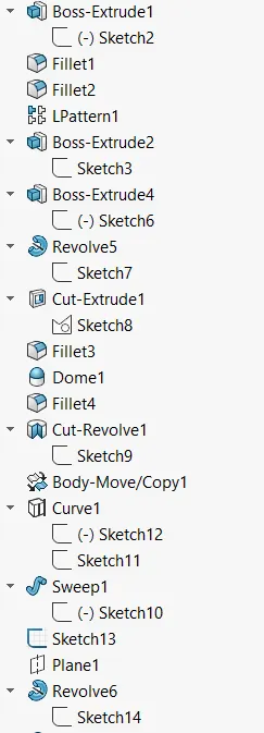
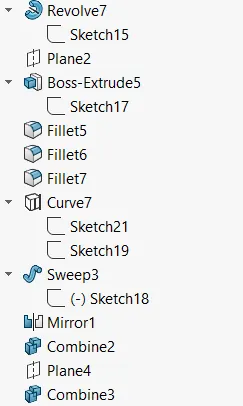
Feature Tree for Front Fork :
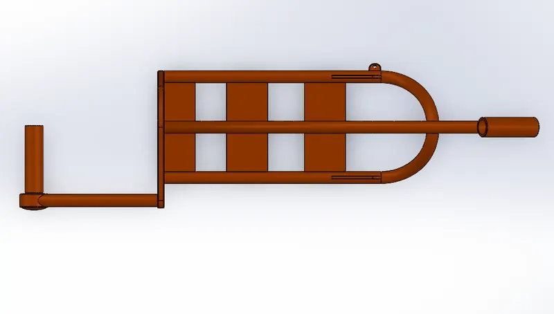
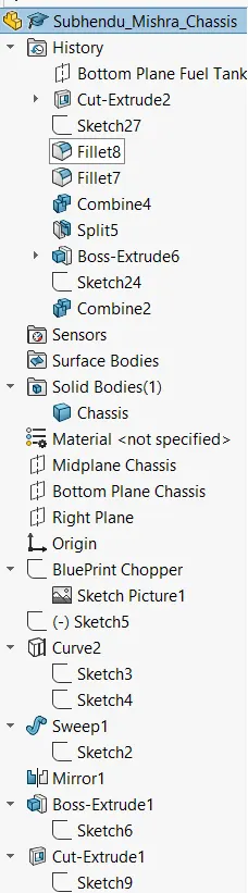
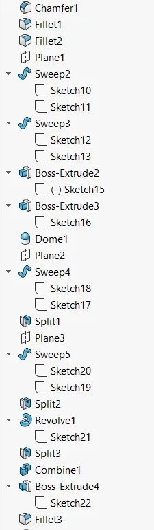
CHASSIS
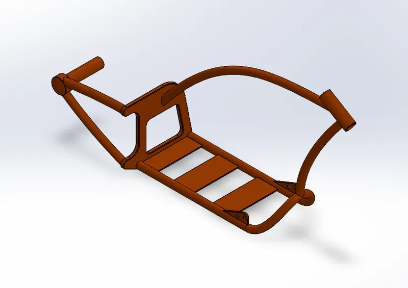
Isometric View
Front View :
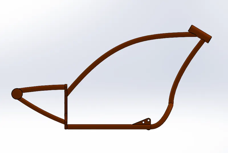
Right View
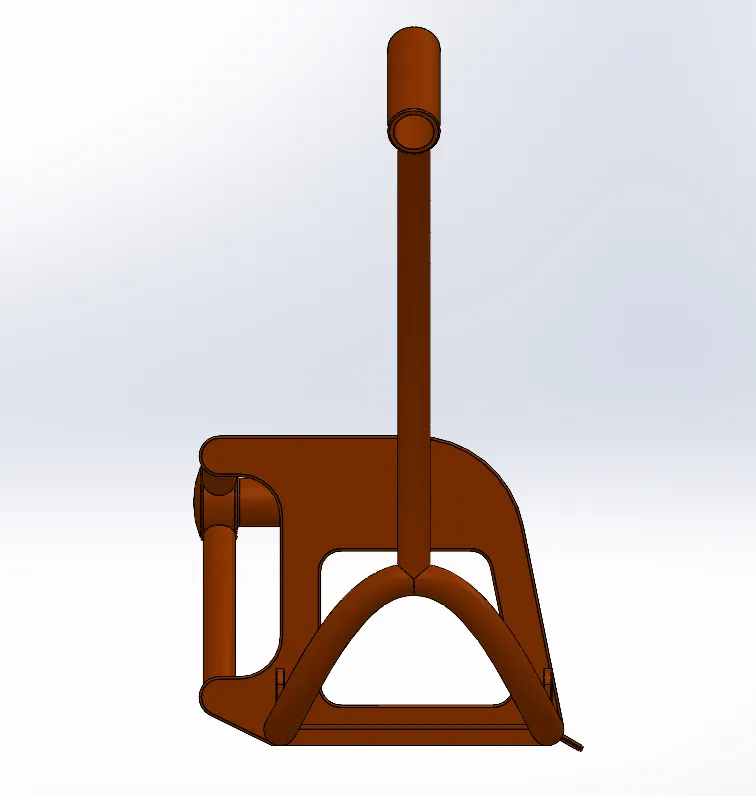
Top View
Feature Tree :
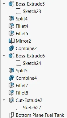
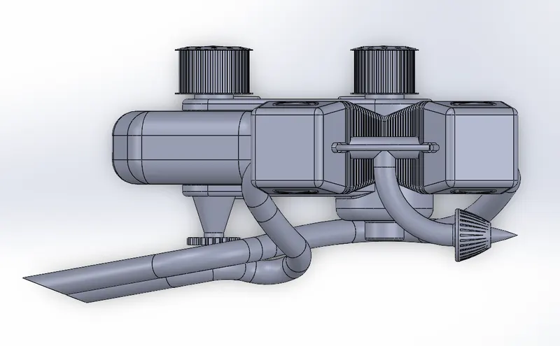
ENGINE
Isometric View
Front View
Right View
Top View
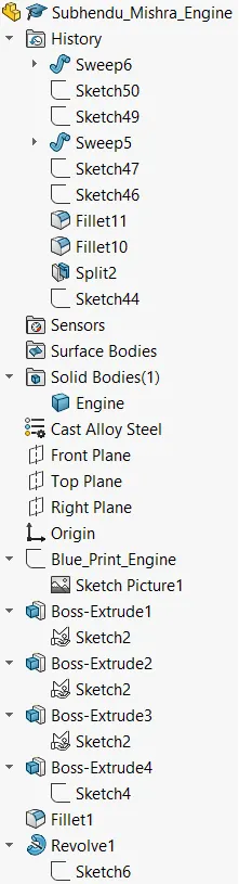
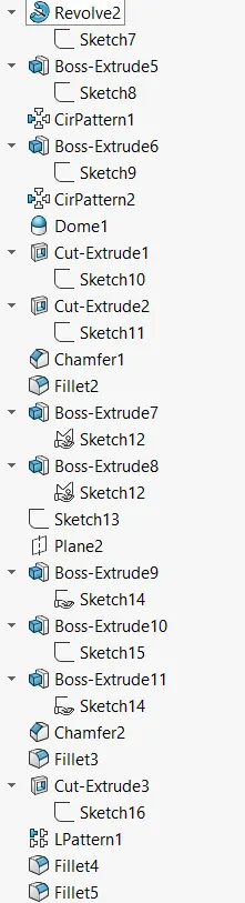
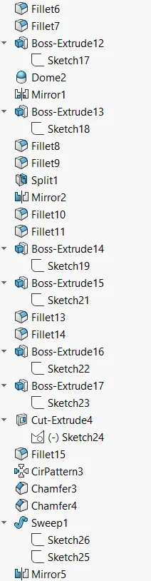
Feature Tree :
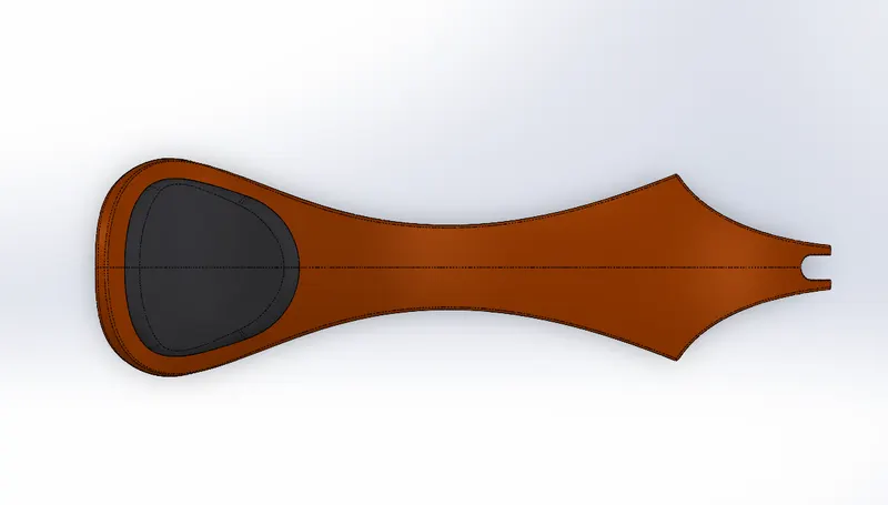
GAS TANK
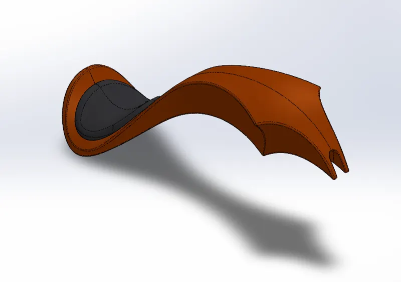
Isometric View
Front View
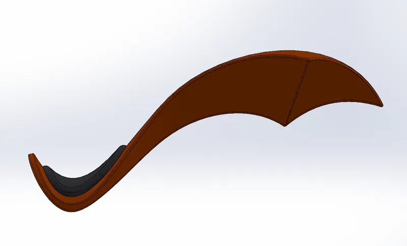
Right View
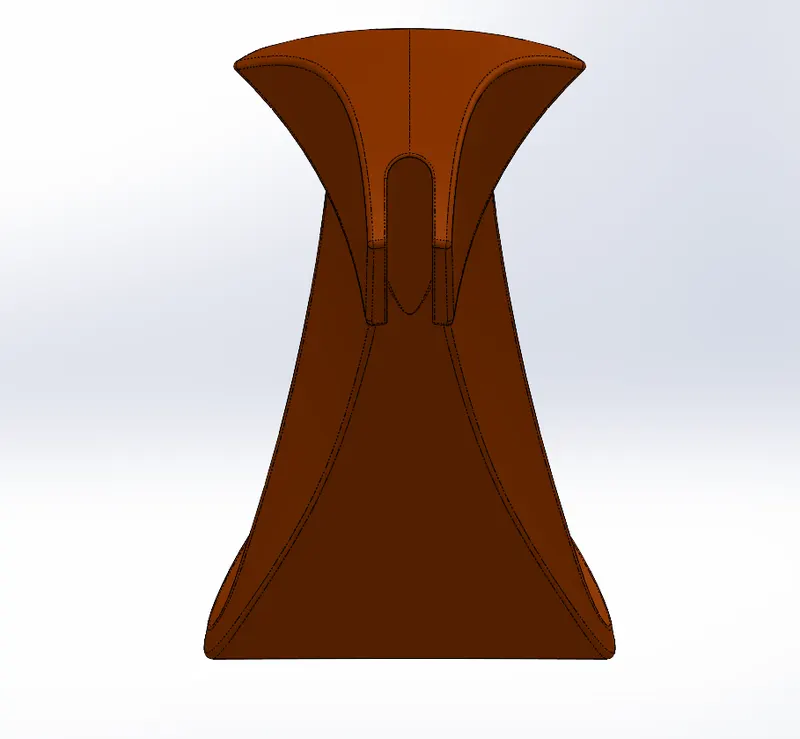
Top View
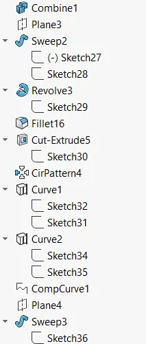
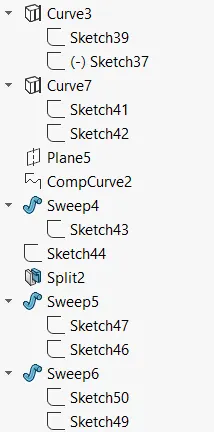
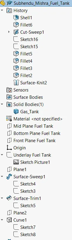
Feature Tree
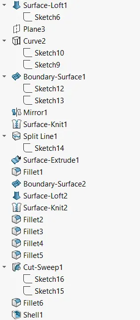
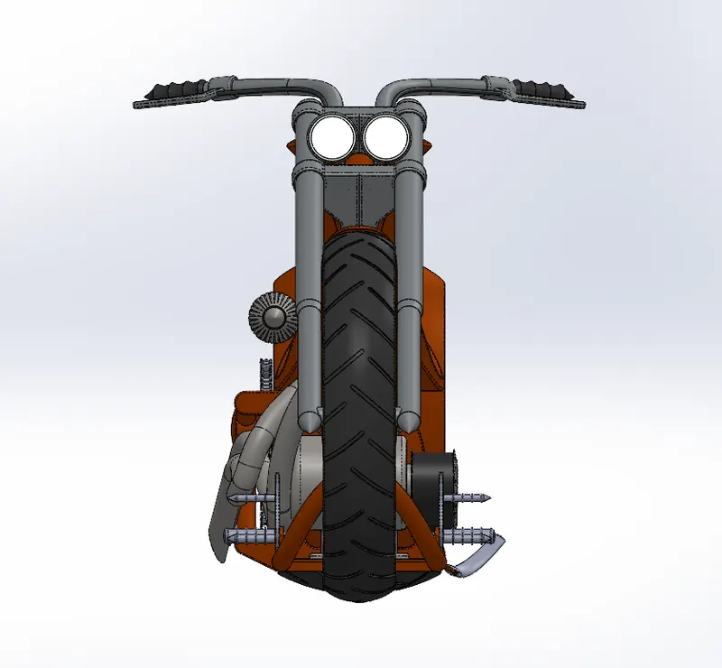
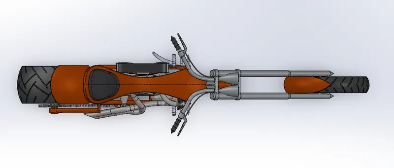
Part 2 : ASSEMBLY
Isometric View
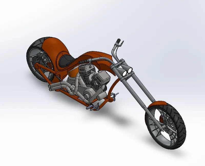
Front
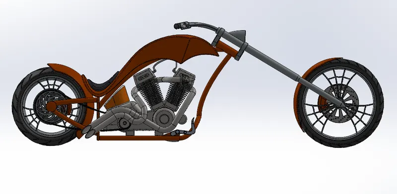
Right
Top
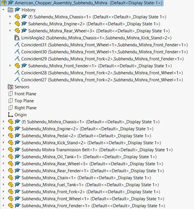
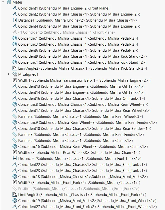
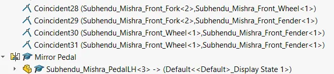
Feature Tree for Assembly
PART 3 : Adding Decals
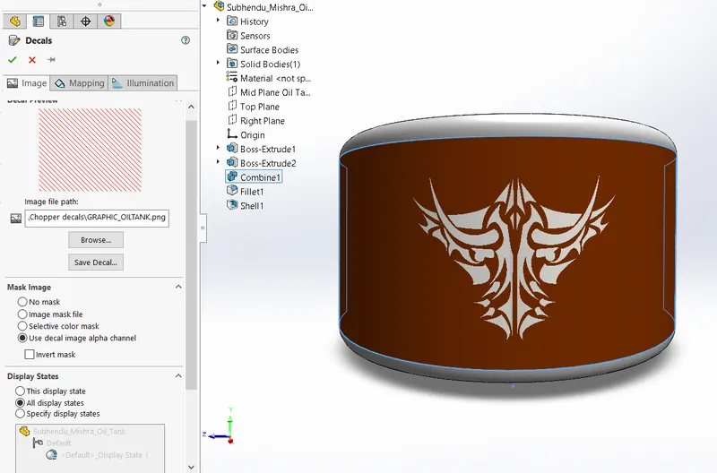
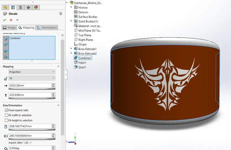
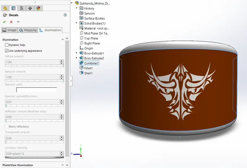
1. Oil Tank
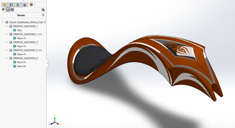
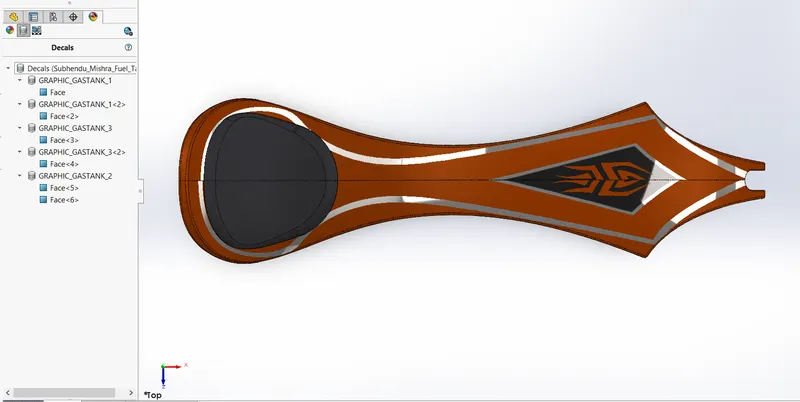
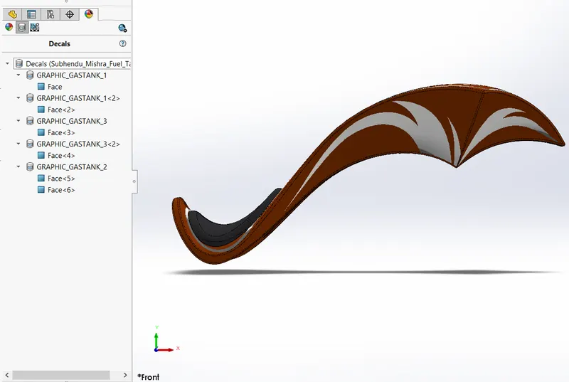
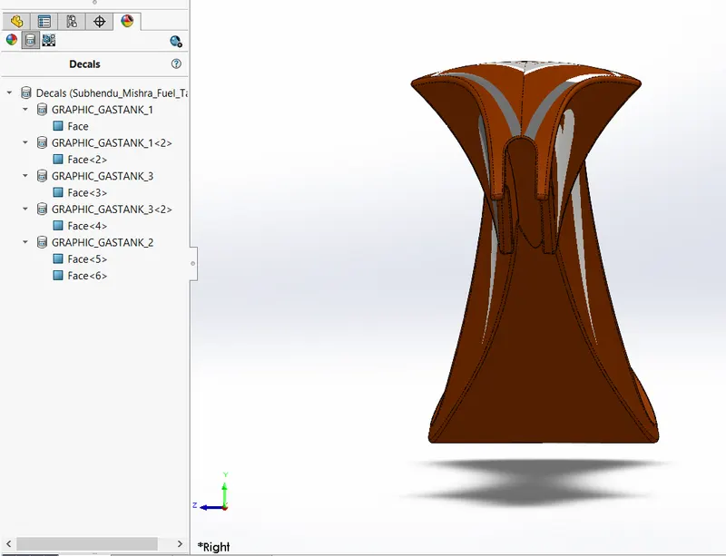
2. Gas Tank
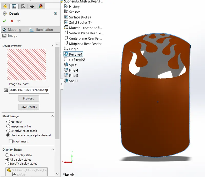
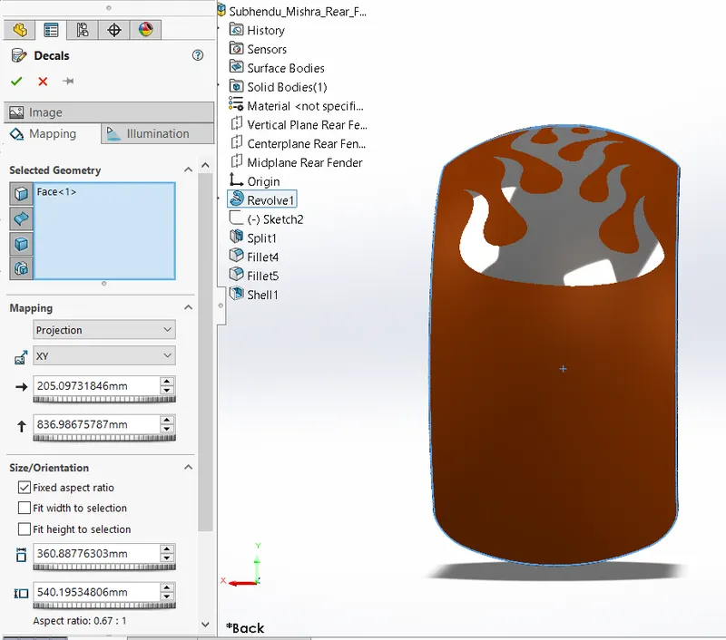
3. Rear Fender
Part 4: Scene Setup
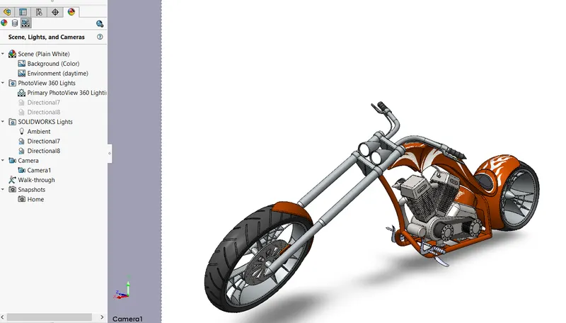
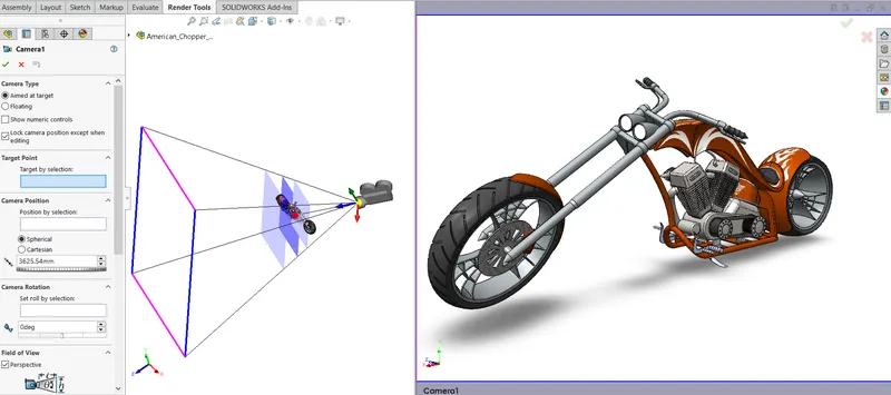
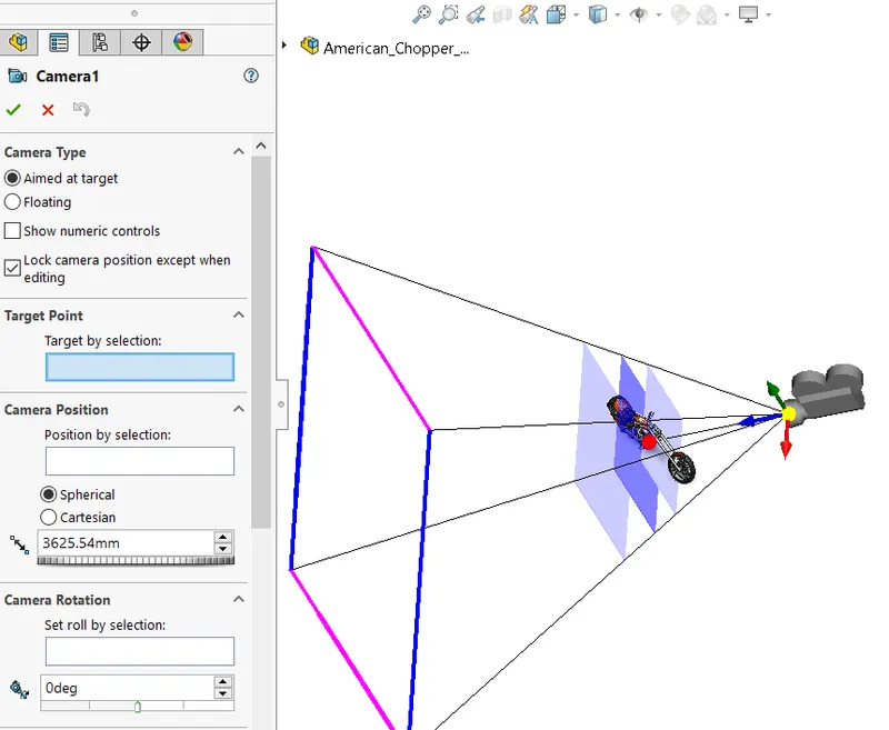
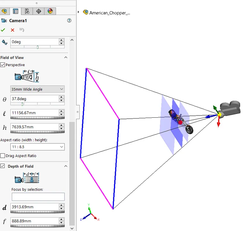
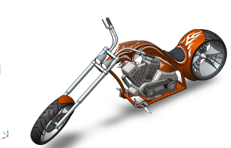
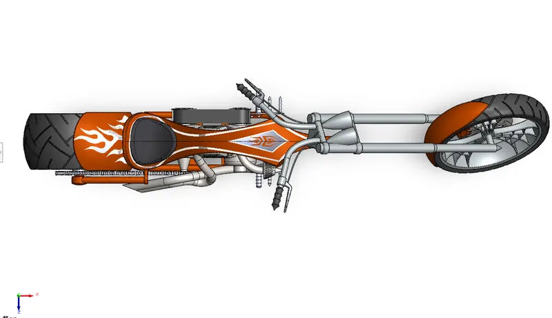
Top View
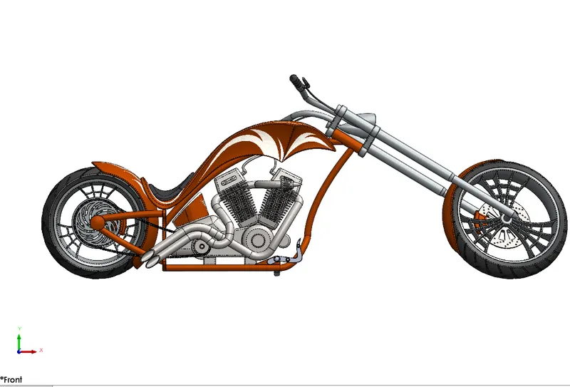
Front View
Part 5 : Rendering
Download Link : https://drive.google.com/file/d/1qWqsMtaMRnv9Y7L02GFEn4vZ4mEsA6Pa/view?usp=sharing