Photo Realistic Rendering
MODELLING AND RENDERING OF AMERICAN CHOPPER
OBJECTIVE:
The objective of this project is to understand and demonstrate the design philosophy of a retro American chopper motorcycle model using new age design tool - Solidworks . American Chopper is two wheeler. Solidworks is 3-D software by Dassault System. Solidworks is used for designing new component, modify component, analysis, managing layout, drawing. In the design, assembly and the rendering phases, usage of sketch tools and making sure that it is fully defined, importance of mates in assembly, usage of rendering tools in Photoview 360 as well as Solidworks Visualize is completely understood.
INTRODUCTION:
American Chopper is a two wheeler. I used Solidworks to design American Chopper. There are different modules in Solidworks which are used to design different component . Computer Aided Design (CAD) software like Solidworks is very simple to use for the creation of 3D solid model and can be created faster. The main advantage of Solidworks is that everyone can use it as compared to other cad software . Solidworks is mainly used in many industries for the design and assembly of there product due to which productivity increases and the cost is also less. With the equation tool in Solidworks it is easy to write all the global variables and evaluate the dimension through global variables.
In Solidworks, we use different module for different purpose. Here we use Sketch Module, Surface Module, Features Module, Evaluate Module, Render Module, Solidworks Visualize Module, etc. for designing American Chopper. In Sketch Module, we use Line Command, Rectangle Command, Circle Command, Are Command, Spline Command, Fillet Command, Chamfer Command, Point Command, Trim Entities, Convert Entities, Offset Entities, Mirror Entities and Pattern Command.Features Module, we use Extruded Command, Revolved Command, Swept Command, Lofted Command, Boundary Command, Extruded Cut Command, Revolved Cut Command, Swept Cut Command, Lofted Cut Command, Boundary Cut Command, Hole Command, Fillet Command, Chamfer Command, Pattern Command, Dome Command, Rib Command, Draft Command, Shell Command, Wrap Command, Intersect Command. Mirror Command, Move Command, Reference Geometry, Curves, Split Command and Combine Command. In Surface Module, we use Extruded Surface Command, Revolved Surface Command, Swept Surface Command, Lofted Surface Command, Boundary Surface Command, Filled Surface Command, Planar Surface command,Trim surface command.
In Assembly Module, we use Insert Components Command, Mate Command, Linear Component Pattern Command, Move Component Command, Rotate Component Command, Assembly Features Command, Reference Geometry, New Motion Study, Bill of Material, Exploded View Command and Interference Detection Command.
EXECUTION:
* Open a new fille
* Selection of plane
* Sketch as per dimension
* Surface modelling or solid modelling
* Fillet or chopper
* Save the design or model
MODELLING:
CHOPPER PARTS
1.Chassis
2.Engine
3.Front fork
4.Pedal
5.Chain
6.Oil tank
7.Gas tank
8.Transmission belt
9.Front fender
10.Rear fender
11.Front fender
12.Rear wheel
13.Kick stand
DESCRIPTION OF THE PARTS AND FEATURES USED:
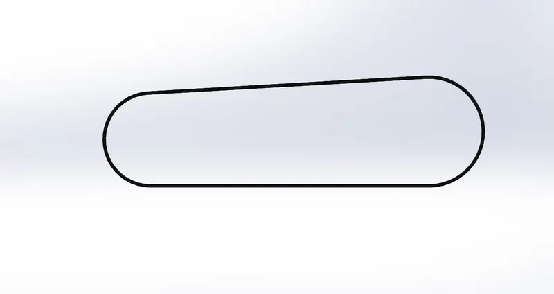
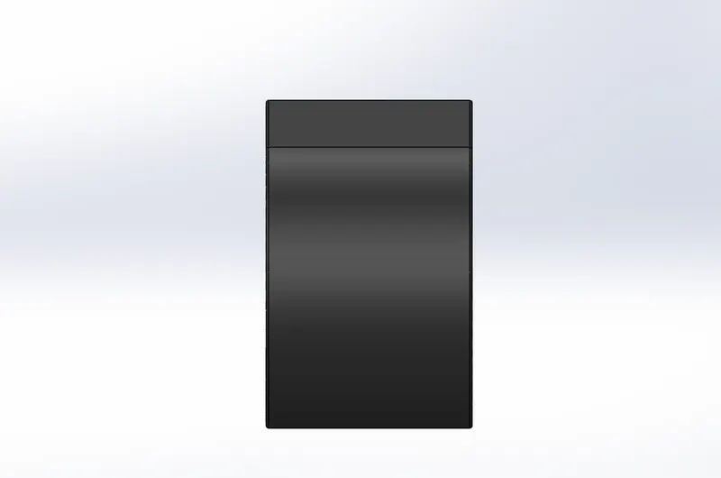
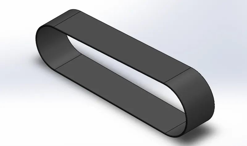
1.TRANSMISSION BELT
The transmission belt is used to transfer power from the output shaft of the engine to the input shaft of the gear box. Polyster material with the layers ar kevlar and sandwich with metallic wires is usually made. It's a combination of different components that gives it strength to transfer the full horse power produced from the motor to the gear box.Transmission belt is a machine component used to transmit power from one shaft/ pulley or a rotating component to another. These belts are made mostly of Rubber canvas material having upsides such as low slip, long life and low maintenance costs. The only downside of belt is power lost during transmission.
FEATURES USED:
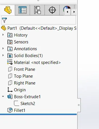
* Boss Extrude
* fillet
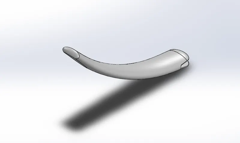
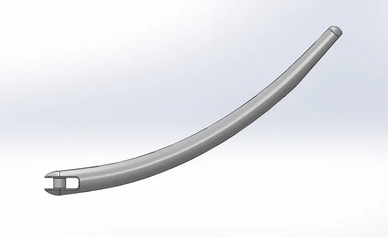
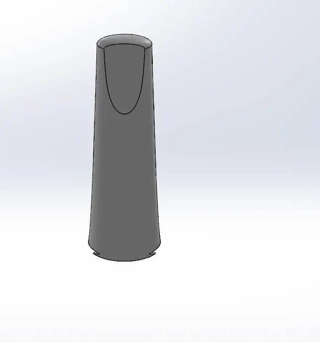
2.KICKSTAND
Kick stand is a supportive framework its provided to a motorcycle to help it stand while stationary in a vertical positon.
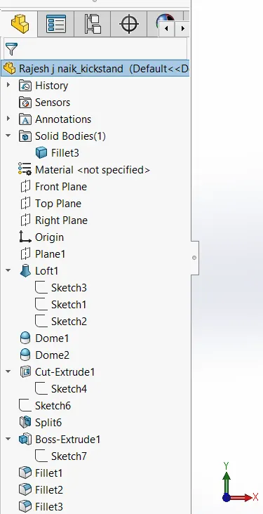
FEATURES USED:
- Sketch
- Loft
- Dome
- Extrude boss
- Extrude cut
- Fillet
- Split
- Appearances
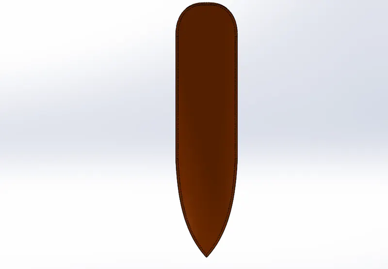
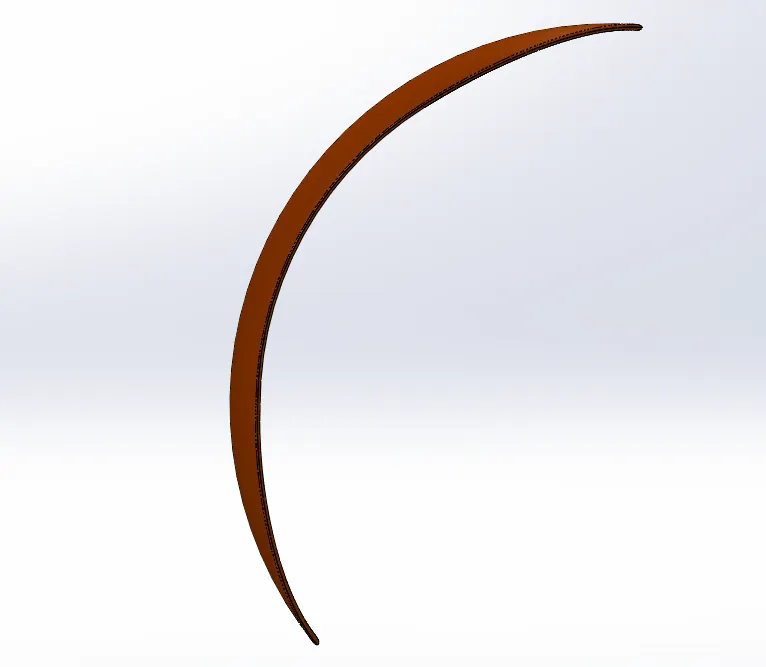
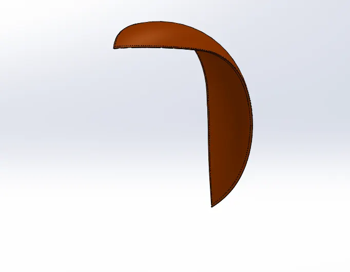
3.FRONT FENDER:
A fender is an automobile part that is bound to the vehicle frame and is placed as a cover on the upper side of the tyres. Its primary purpose is to prevent sand, mud, rocks, liquids, and other road spray from being thrown into the air by the rotating tire. Front wheels require the fenders to provide mud and gravel protection on the rear side i.e., the rider side and the engine. This part is also known as mud guard.
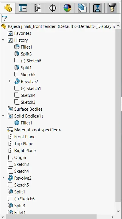
- Sketch
- Offset Entities
- Trim Entities
- Revolve
- Dynamic mirror
- split
- Appearances
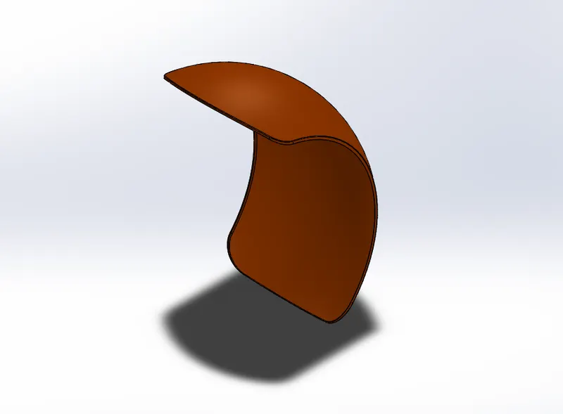
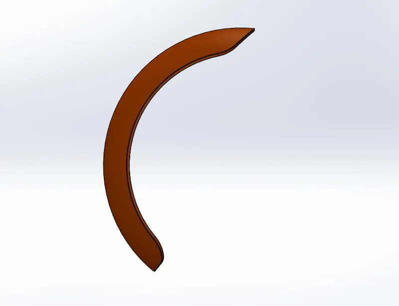
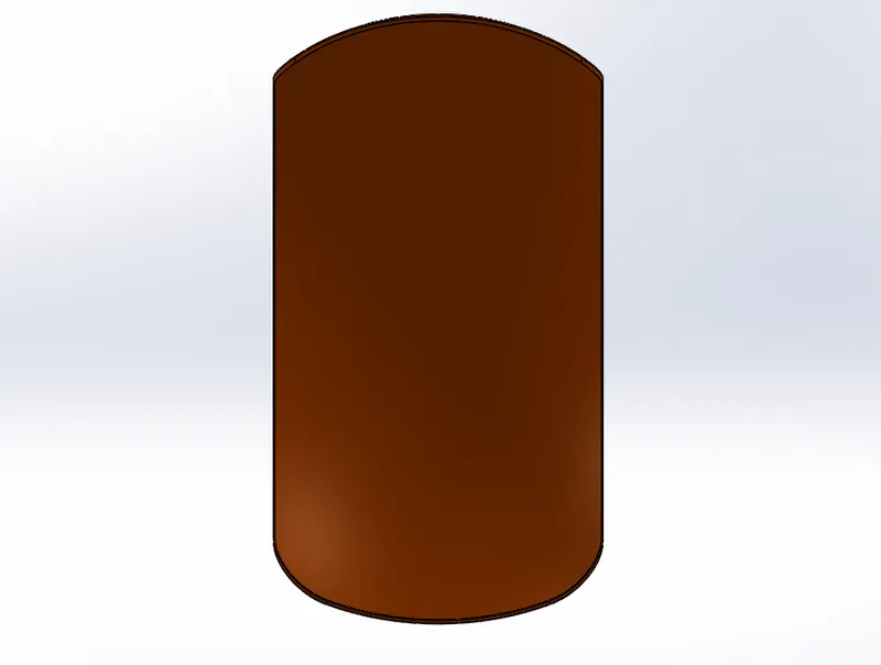
4.REAR FENDER:
A fender is an automobile part that is bound to the vehicle frame and is placed as a cover on the upper side of the tyres. Its primary purpose is to prevent sand, mud, rocks, liquids, and other road spray from being thrown into the air by the rotating tire. Front wheels require the fenders to provide mud and gravel protection on the rear side i.e., the rider side and the engine. This part is also known as mud guard.
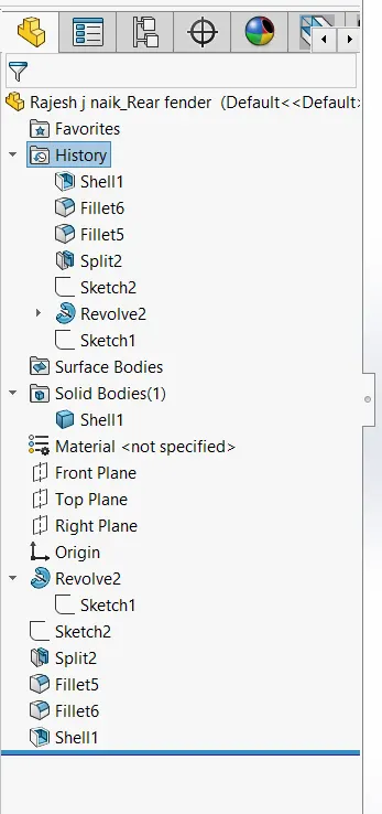
FEATURES USED:
- Sketch
- Offset Entities
- Trim Entities
- Revolve
- Appearances
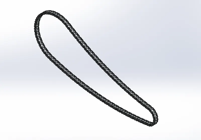
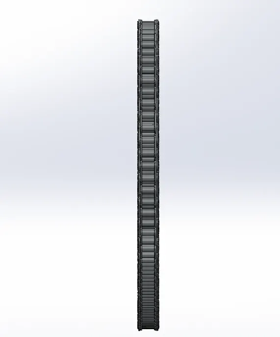
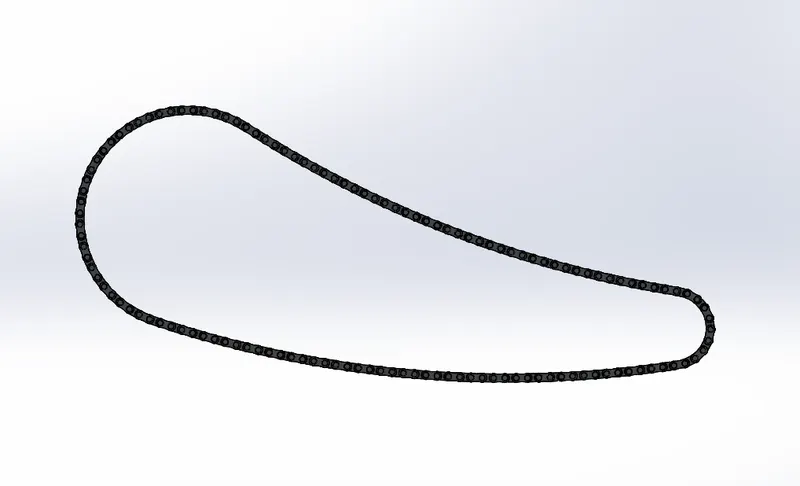
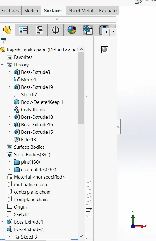
5.CHAIN:
Chain is the connection is used to transmit power from the rngine to the rear wheel. It passes over toothed member known as sprocket.A chain is a set of several links made of small plates and pin joints, connected in a loop to make a power transmission component. This is mainly used to transmit power from one shaft to another using sprockets as connecting means to the shafts. The main advantage of chain is high power transmission capacity, good flexibility, low cost. The disadvantage of chain is high maintenance.
FEATURES USED:
- Sketch
- Trim
- Fillet
- Blocks
- Extrude
- Mirror
- Patterns
- Appearances
6.OIL TANK
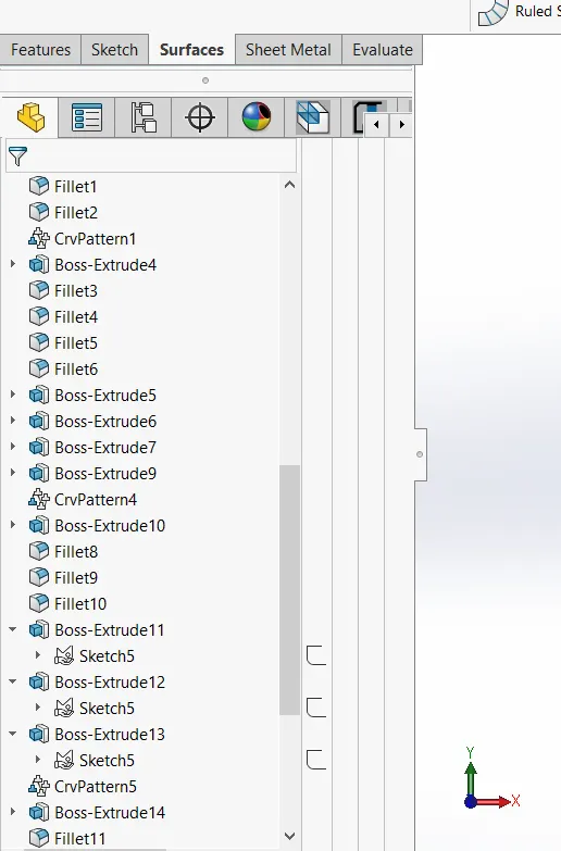
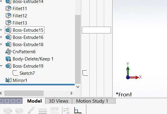
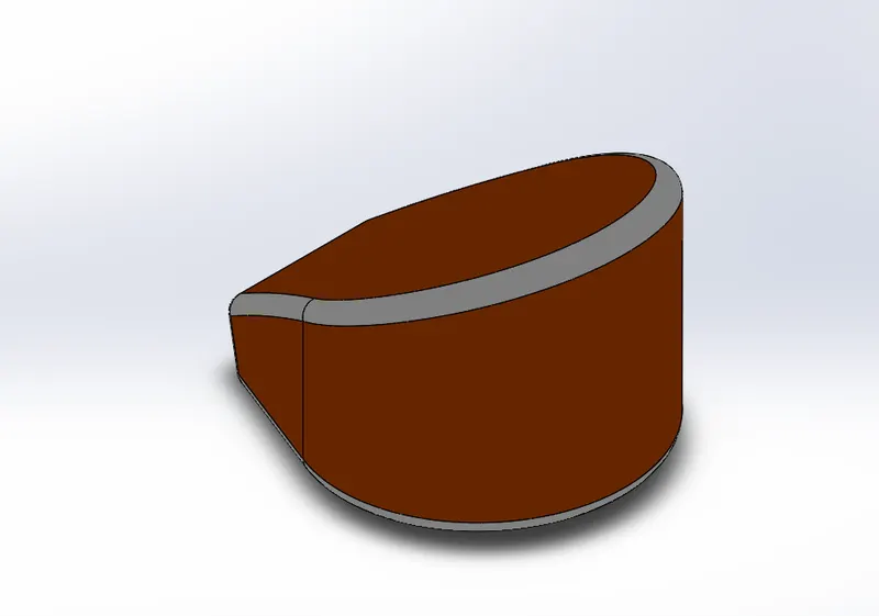
The purpose of oil tank is to store lube oil to lubricate the engine component to prevent wear and tear due to excessive heat.Oil tank is a component used to store the oil for lubrication and cooling purposes of engine components. Oil tanks can be of various kinds like engine oil tank, coolant oil tank, radiator oil tank etc. The oil tank used in this American chopper model is used for engine lubrication and cooling. This tank is placed right below the rider seat on top of the gearbox.
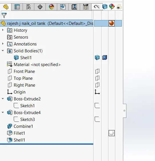
FEATURES USED:
- Sketch
- Boss Extrude
- Combine
- Fillet
- Shell
- Appearances
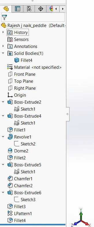
7.PEDAL
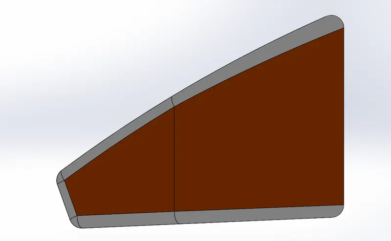
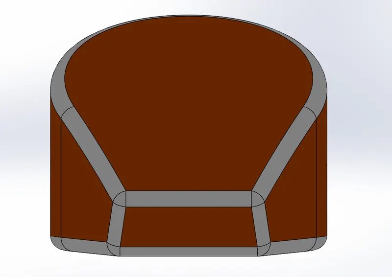
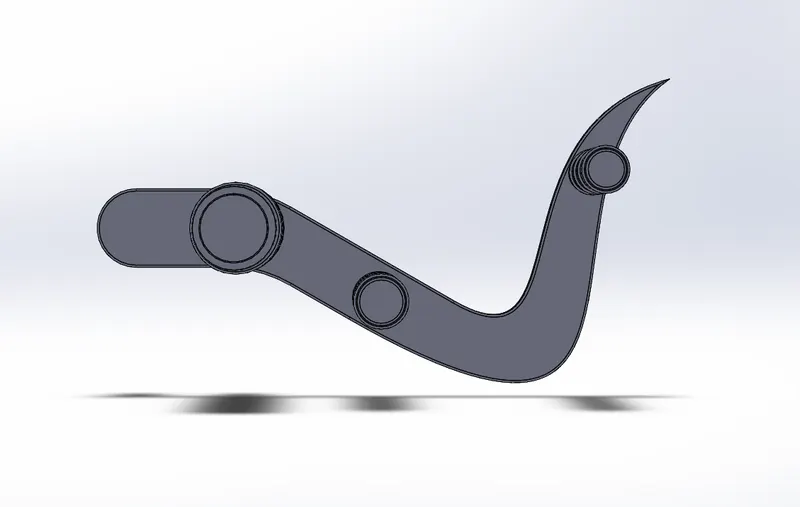
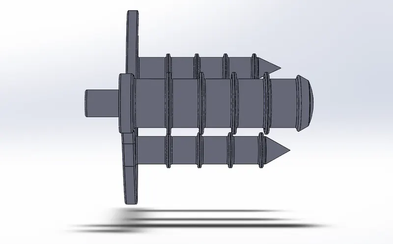
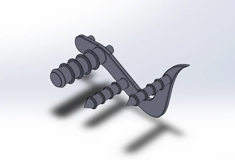
The external part mounted to the frame is the pedal.To rest the leg on top of that, the pedal is used for the convenience of the rider.A pedal is a motorcycle component used by the rider to place his/her foot on it while riding the bike. This is also called foot peg and is mounted on both sides of chassis.
Its position depends on the type of motorcycle. In a chopper type motorcycle, the pedals are placed in forward position such that the legs of the rider are fully extended in a comfortable manner. The pedals also contain protruded sections so as to provide grip to the rider's foot to avoid any kind of slippage. The brakes and the gear shift pedals are mounted on each of the pedals or are nearly placed.
FEATURES USED:
- Sketch
- Extrude
- Fillet
- Linear pattern
- Dome
- Chamfer
- Appearances
8.FRONT WHEEL
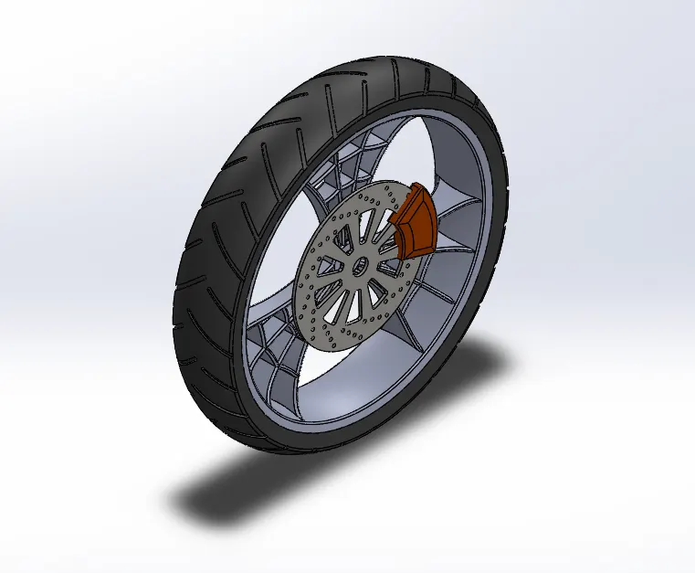
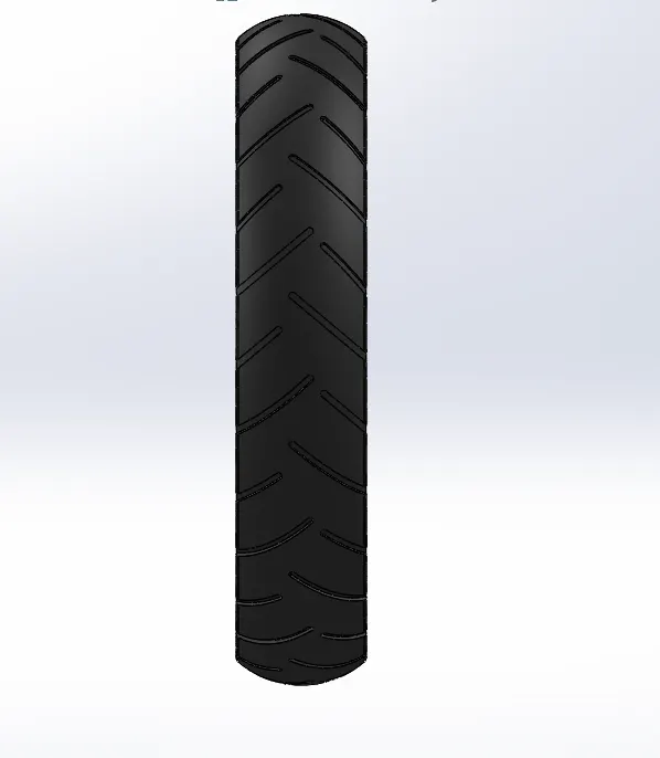
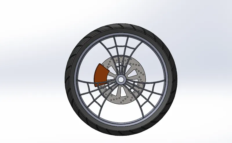
A wheel is a circular block of a hard and durable material with a circular hole through an axle bearing around which the wheel rotates, wehre the middle has been drilled.Wheel consists of the rims and the tyre which make it the component that makes connection between the motorcycle and the ground. The rim is an important strength component which ensures safe load carrying capacity of the bike. It should have high compressive strength so as to ensure safety while moving. It should be able to absorb shocks and impacts. The tyres are the main contact surface to the ground. It is generally made up of rubber to ensure flexibility and bump absorption. The tyres contain treads which provides grip to the road. The wheel also houses a Disc brake rotor and its calliper.
Front wheels of choppers are always larger than the rear wheel with narrow section as compared to the latter.
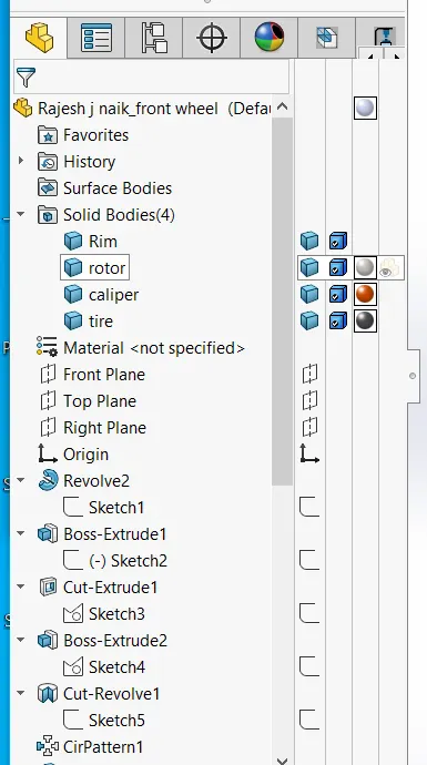
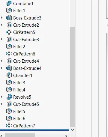
FEATURES USED:
- Extrude Boss
- Cut Extrude
- Revovlved Cut
- Circular pattern
- Combine
- Fillet
- Chamfer
9.REAR WHEEL
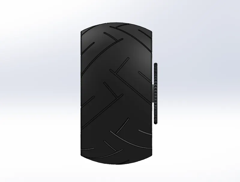
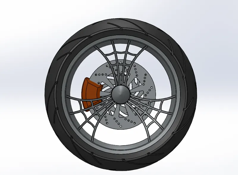
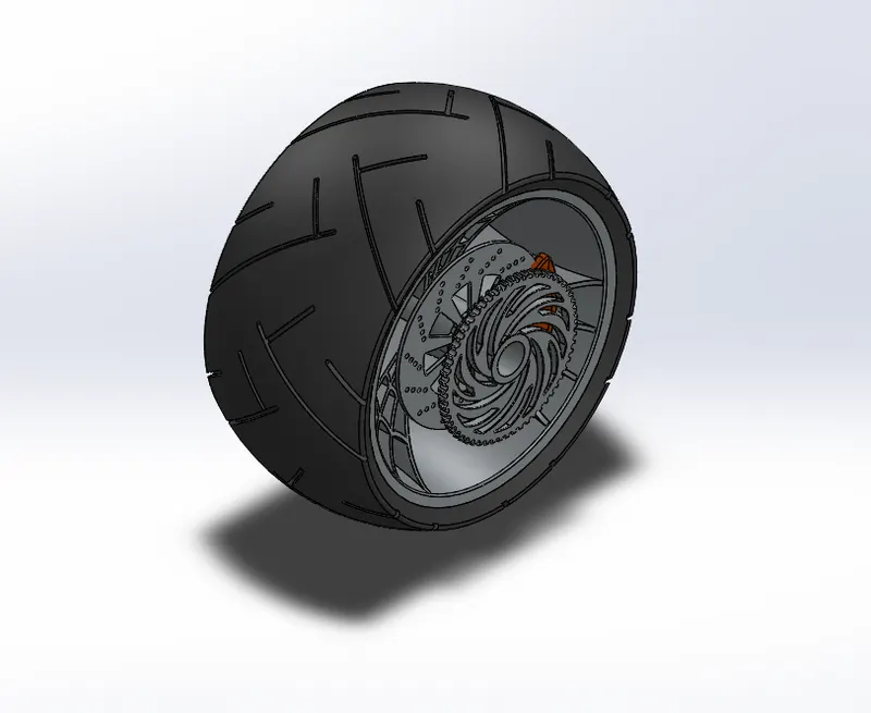
A Wheel is a circular block of a hard and durable material with a circular hole through an axel bearing around which the wheel rotates,where the middle drilled.Wheel consists of the rims and the tyre which make it the component that makes connection between the motorcycle and the ground. The rim is an important strength component which ensures safe load carrying capacity of the bike.
It should have high compressive strength so as to ensure safety while moving. It should be able to absorb shocks and impacts. The tyres are the main contact surface to the ground. It is generally made up of rubber to ensure flexibility and bump absorption. The tyres contain treads which provides grip to the road. The rear wheel also houses a Disc brake rotor and its calliper and specifically a Chain sprocket to drive the wheel using power transmitted from engine.Rear wheels of choppers are generally smaller in diameter than the front wheel having a broad section as compared to the latter. The rear wheel in this American Chopper has a diameter of 484.5mm which is 19 inches.
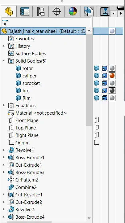
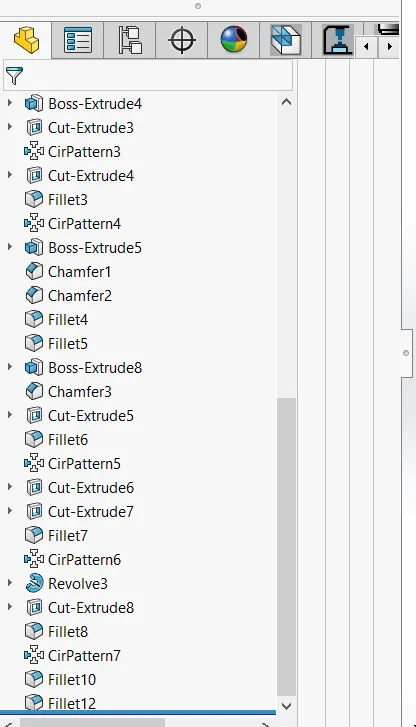
FEATURES USED:
- Sketch
- Revolve
- Trim
- Fillet Entities
- Boss/Base Extrude
- Planes
- Revolve Cut
- Linear pattern
- Chamfer
- Follet Features
- Cut Extrude
- Circular Pattern
- Appearances
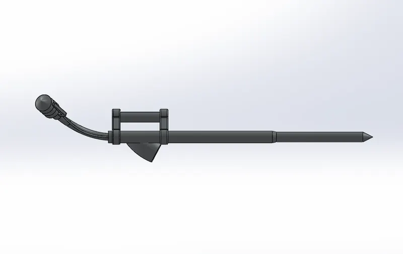
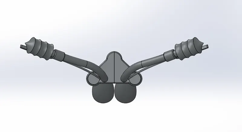
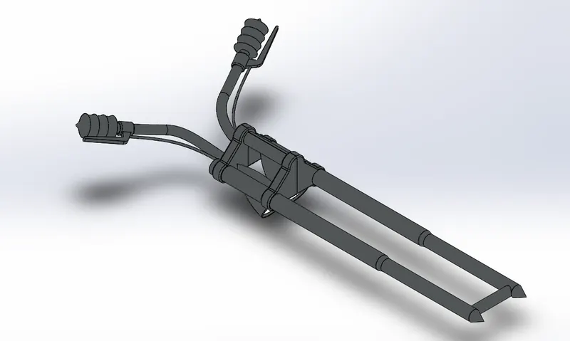
10.FRONT FORK
For the front suspention,most bikes today use telescopic fork. The forks with internal coil springs can more readily be understood as essentially large hydraullic shock absorbers. They cause the front wheel to road imperfections while isolating the remainder of the motorcycle from the motion.Toprovide comfort to the rider, itremoves the bums.
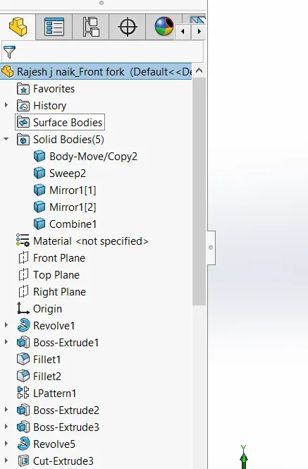
FEATURES USED:
- Extruded Boss
- Revolved Boss
- Fillet
- Extruded cut
- dome
- Revolved cut
- Swept boss
- Project curve
- Mirror
- Combine
Project curve:
The project curve is the type ogf 3D curve that is projected on the basis of two separate 2D sketches.
SWEEP:
We can create a form with the sweep function by moving a 2D sketch profile along a 2D or 3D sketch patch.
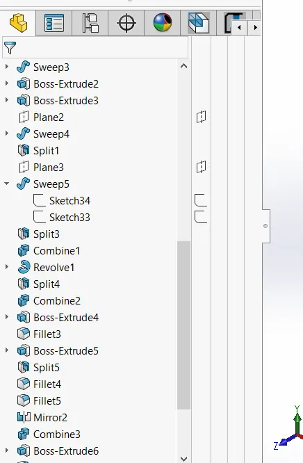
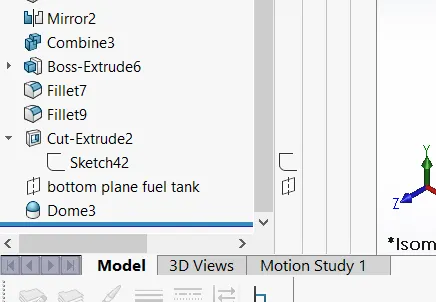
11.CHASSIS
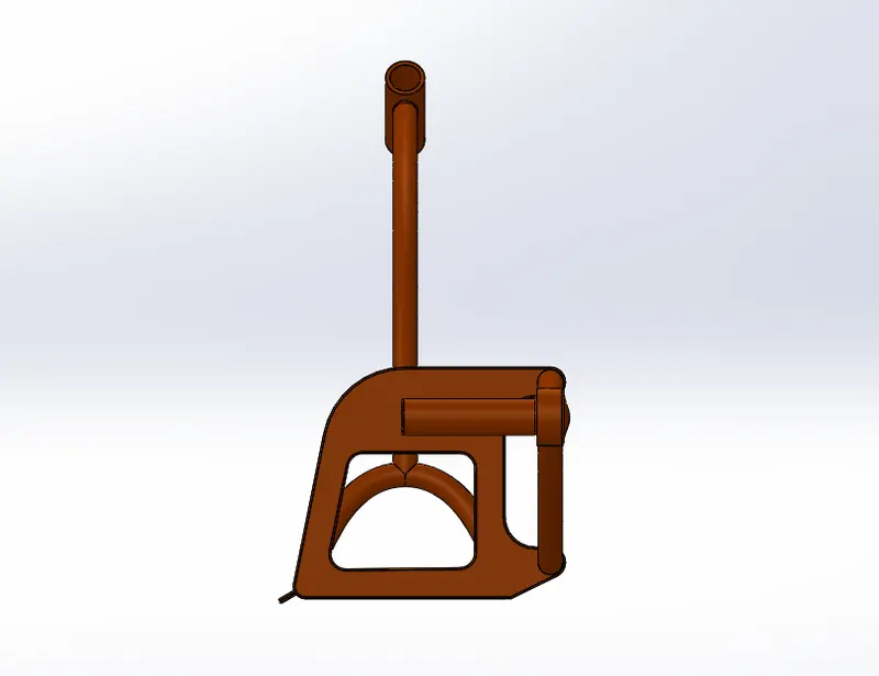
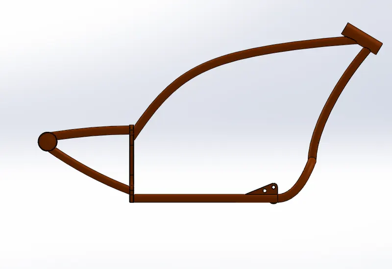
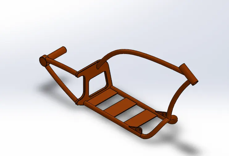
Its skeleton shapes the chassis or assembly.All of a motorcycle's parts, such as the suspention,wheels,fuel tank,seats,handelbars,etc., are related to this simple structure to this simple structure that gives a motorcycle its power and capacity to handle well.The chassis used in this American chopper motorcycle is a rigid hardtail frame chassis which excludes the rear suspension component.
FEATURES USED:
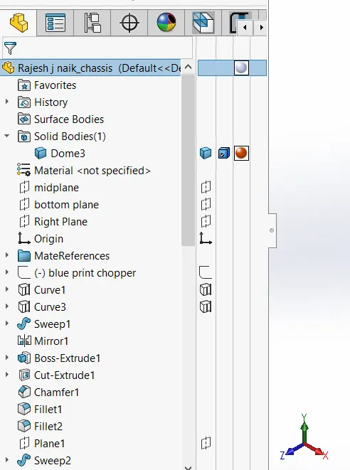
- Sketch
- Offset
- Convert entities
- Project curve
- Trim
- Plane
- Sweep
- Split
- Revolve
- Cut Extrude
- Fillet
- Combine
- Appearances
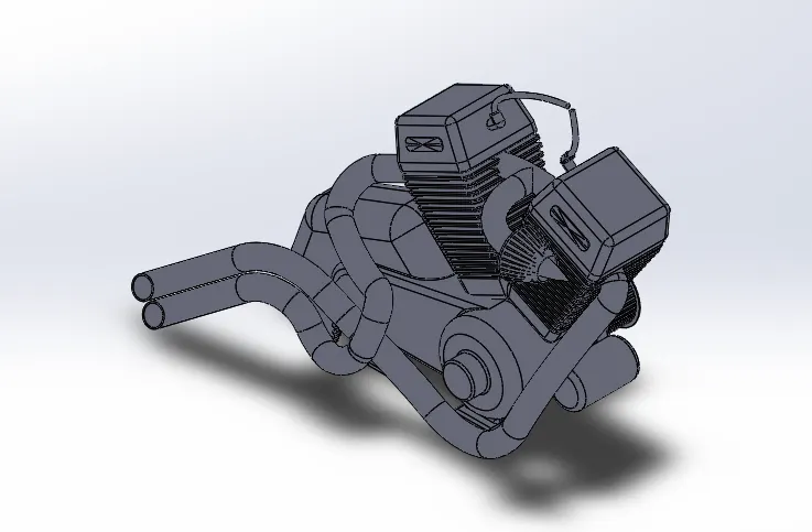
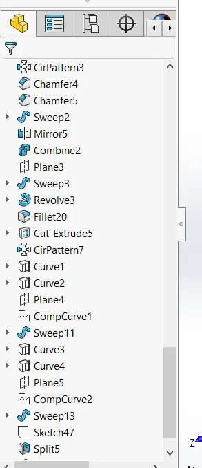
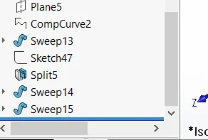
12.ENGINE
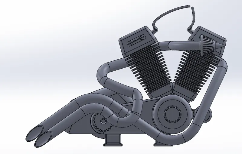
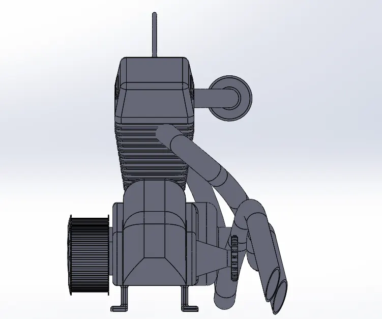
Engine or motor is a system that is designed to transform mechanical energy into one type of energy.Heat engines burns a gasoline,such as the internal combustion engine,to produce heat that is then used to do work.Engine is the main powerhouse of any automobile. Motorcycle engines are generally Internal combustion Spark ignition type. The engine consists of piston-cylinder arrangement which powers the motorcycle. The IC engine houses air intake, exhaust outlet and fuel intake ports.
This American chopper motorcycle has a V-Twin type engine consisting of external air filter, spark plugs 1 for each cylinder, transmission pulleys, air cooling fins, starter motor, front sprocket for chain drive, exhaust pipes and casing for sump and gearbox.
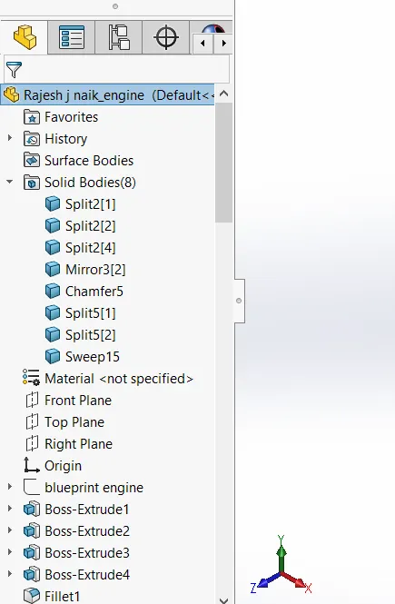
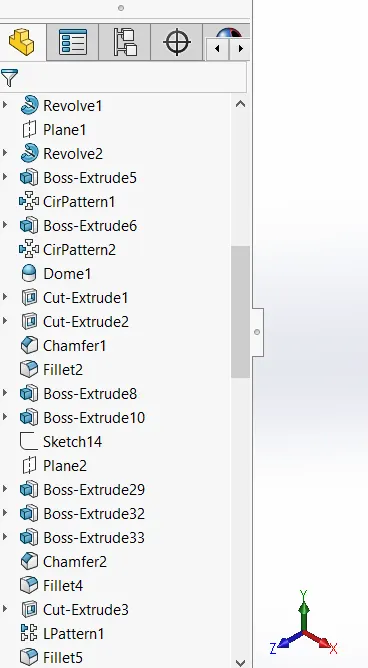
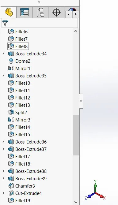
FEATURES USED:
- Sketch
- Convert entities
- Trim
- Revolve
- Boss extrude
- Cut extrude
- Offset
- Dome
- Fillet
- Project curve
- Composite curve
- Sweep
- Mirror
- Circular pattern
- Split
13.GAS TANK
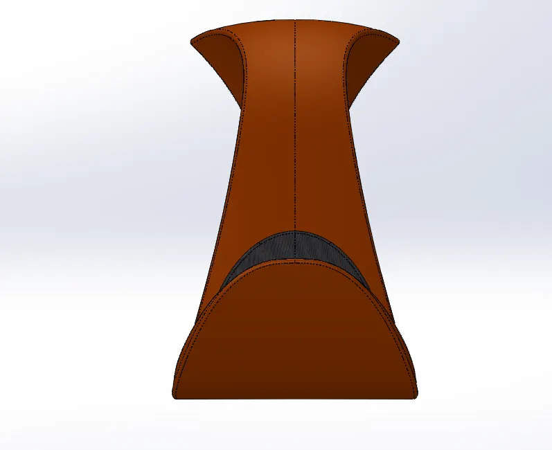
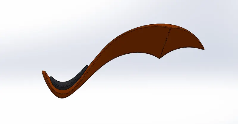
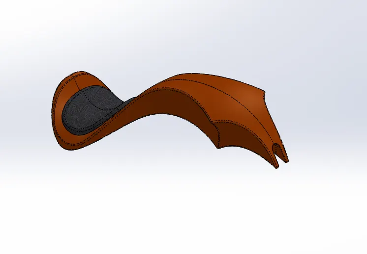
A safe reservoir for flammable fluids is a gas tank.The term is usually applied to part of an engine structure in which the fuel is contained and pushed or released into an engine,but any holding tank for fuel. Fuel tank is the fuel storage component of the motorcycle. It is made to store flammable fluids or gas in a cool state away from the engine heat. Safety of the petrol is the main criteria in designing the fuel tank. It is connected to a fuel pump or a fuel regulator device such as carburettor or an injection system to supply appropriate amount to the engine with proper mixture of air and fuel.The fuel tank of this American chopper is made to house a seat and fit to the chassis centrally with the mount. It is made up of surfaces and finally these surfaces are knit together to form a complete solid body with hollow shell to store fuel.
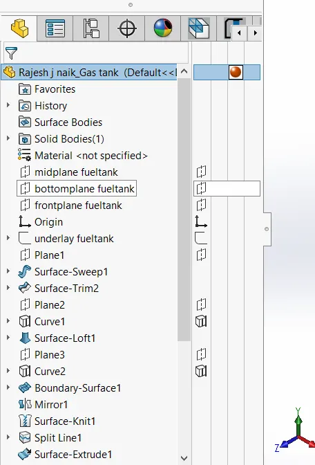
TEATURES USED:
- Sketch
- Trim
- Project curve
- Convert entities
- Sweep surface
- Loft surface
- Fill surface
- Surface trim
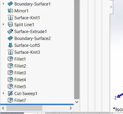
- Surface knit
- Sweep cut
- Fillet
- Appearances
LOFTED SURFACE:
- Loft surfaces are surfaces developed by several 3D curves or existing edges that create a smooth tangency between the curves choosen.
SWEPT SURFACES:
- Sweep Surfaces are surfaces created along a path from a segment curve.
FILLED SURFACE:
- A surface patch with any number of sides is built by the Filled Surface function, inside a boundary defined by existing model edges, sketches, or curves, including composite curves.
SURFACE TRIM:
- It is mainly used to cut material away from a board, and offers two modes: Normal and Shared.
EXTEND SURFACE:
- To expand the surface that is already made, Extend Surface is used. On the expanded board, there are various choices available. Wecan expand the surface to the same surface,or we can extend the tangent of the surface to the surface.
SURFACE KNITE:
- The two free edges / open edges of the surfaces are knit together by Surface Knit. It also eliminates the distance between the two surface edges.
13.ASSEMBLY
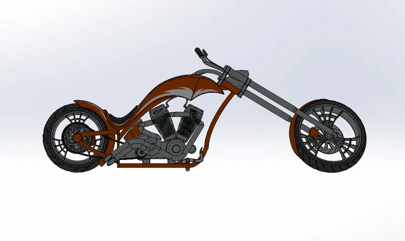
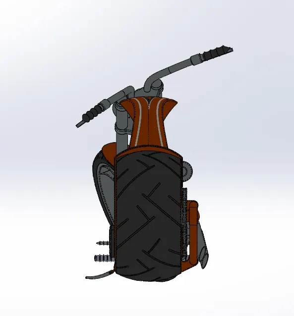
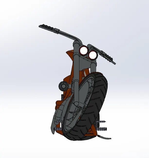
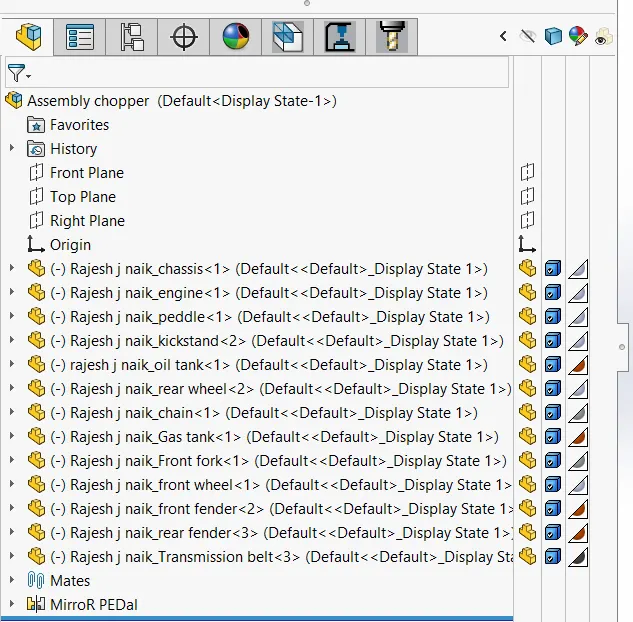
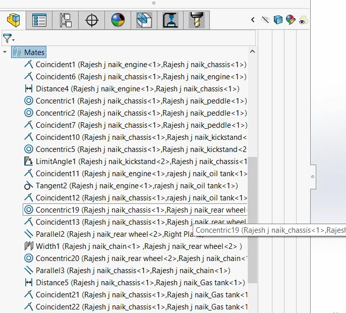
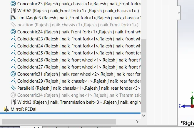
In SolidWorks, all the designed parts are taken into the assembly section and the whole assembly of the American Chopper is produced using distinct mating characteristics such as concentric, coincident, parallel, etc. The decals are added to the chopper after assembly.The assembly of the chopper consists of all the parts attached in appropriate manner with proper mates. The main component chassis is first fixed and other parts are mated with respect to its position.
PROCEDURE FOR ASSEMBLY:
- Fix the chassis position on the Front plane of the assembly coincident to mid plane chassis.
-
Give relation coincident Mid plane chassis and front plane engine.
-
Make the engine mounts coincident to the base plate of chassis and 20mm behind the vertical face of plate.
-
Make the pedals concentric and coincidentto the mounts and mirror the part appropriately.
-
Use coincident, concentric and limit anglemates with kickstand and mount.
-
Give relation coincident Mid plane chassis and Right plane rear wheel and make the axle hole concentric to the Hub axle on swingarm.
-
Give relation parallel to right plane chassis and front plane of rear wheel.
-
Make rear fender concentric to rear wheel and give relation parallel to vertical plane Rear Fender and Right plane chassis.
-
Give relation coincident to mid plane chassis and mid plane rear fender.
-
Give width mates, concentric and angle mates to transmission belt on pulleys.
-
Make oil tank coincident on gearbox face and give relation of coincident to Midplane chassis and mid plane of oil tank.
-
Back edge of oil tank coincident to the edge of gearbox.
-
Make front forks concentric to the steering stem and give width mates on the chassis, limit the rotation to 30° in both directions.
-
Make a central position mate and suppress it.
-
Give parallel relations between midplane chain and midplane chassis; parallel relation between Bottom plane chassis and centre plane chain.
-
Make bottom plane FT coincident to plane created in chassis.
-
Make Midplane FT and Midplane Chassis coincident.
-
Give a distance mate of 5mm for Front plane FT from plane 1 in chassis.
-
Give relation coincident to Midplane forks and right plane front wheel.
-
Make the axle concentric to axle hole.
-
Use coincident relations to straighten the front wheel with respect to the front forks.
-
Make the front wheel, rear wheel and the kickstand tangent to the top plane of the assembly to give it a rest position.
- And save the assembly.
FEATURES USED:
- Mates
Mates in assembly environment is analogous to relations in part environment. Basically, it is the relation between two different components. Solidworks assembly mates consists of 3 main mates namely Standard mates, Advanced mates and Mechanical mates.Standard mates consist of: Coincident, Concentric, Parallel, Perpendicular, Tangent, Lock, Mate alignment angles and distance mates.Advanced mates consist of Profile centre, Symmetric, Path mate, Width mate, Linear/Linear coupler, Angle and distance mates.Mechanical mates consist of Cam, Slot, Hinge, Gear, Rack & Pinion, Screw, Universal joint. The analysis tab under mates is used to define motion analysis between two components.
RENDERING
Rendering of the assembly is done to make a good quality 2D images for the purpose of advertising and prom of the products before selling it to the customers. Photorealistic rendering creates high quality images or motio graphics if available so as to look appealing in various environments and backdrops.
Solidworks provides 2 rendering products:
-
Photoview 360 which is inbuilt add in for Solidworks.
- Solidworks Visualize which is a separate Render Engine.
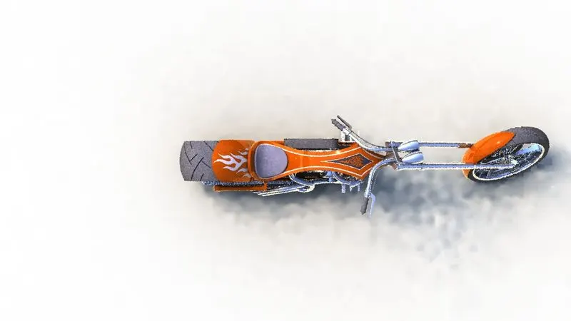
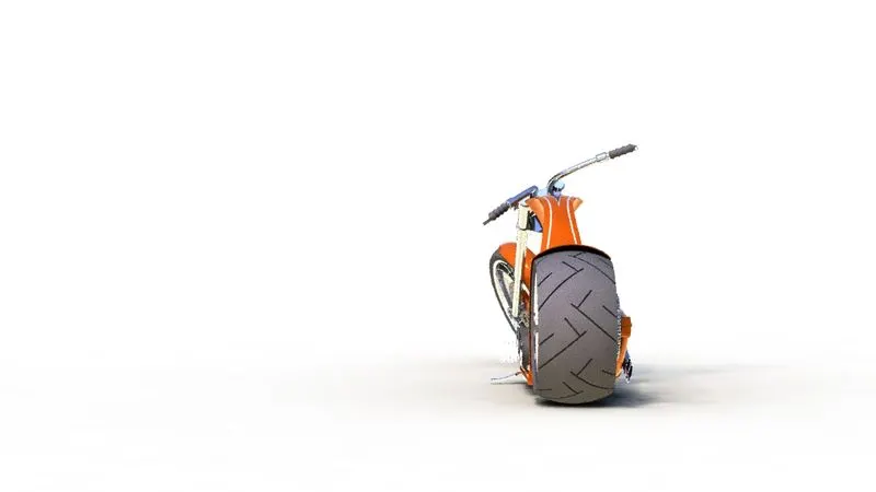
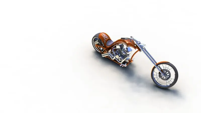
Photoview 360
- After adding photoview 360 the render tools tab can be brought in
- It has various options like preview window, render region, final render, edit appearance, edit scenes, and options for managing render quality, Bloom, cartoon, direct caustics, network rendering and final image type.
- Schedule render and recall last renders are also some options.
- Decals can be added using edit decals, image can be added on faces by mapping values in coordinate directions. Illumination can be set to underlying appearance for better blending of decals.
- Display states can be set for parts individually so as to provide multiple appearances to a single part and changing the appearance whenever required.
- From view dropdown- Lights and camera is for setting up camera views and lighting of the scenes.
SOLIDWORKS VISUALIZE:
-
Solidworks Visualize provides a suite of standalone software tools that combine industry-leading rendering capabilities with visual design-oriented features and workflows, allowing easy and fast creation of visual content that communicates a design's vision, passion, and emotion.
-
It is a separate render engine that is provided under solidworks professional.
-
Visualize Professional adds an array of features including animations, custom lighting, VR, 360 Interactive, and much more.
-
Solidworks Visualize Professional provides the highest level of detail and optimized render times.
-
It helps in creating Rendered images of the solidworks models in Photorealistic environments for marketing quality images with various options to tweak on the final image required as per the user.
-
It uses either of the CPU or GPU or both as hybrid to render quality images.
-
Import the assembly and select part grouping as appearance, this ensures that all the parts having same appearance are grouped together in appearance tab.
-
All parts having same appearance can be tweaked together using appearance options. • Setting up of background can be done from scenes tab which includes a wide range of HDR images and backgrounds. Background brightness, rotation, gamma can be changes as required from the scenes tab.
-
Camera views can be added or used from assembly.
-
Render output image properties can be changed from output tools. Things such as image size, animation, photograph scenes, usage of CPU, GPU or both as hybrid can be selected.
-
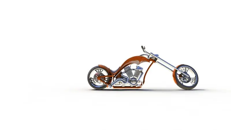
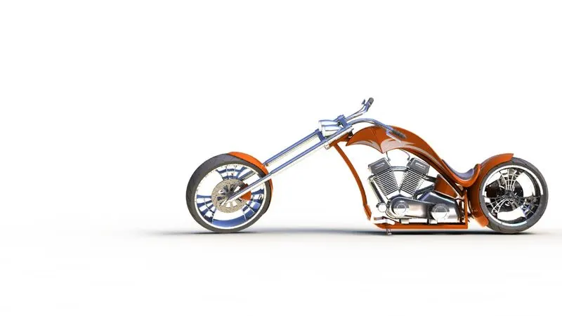
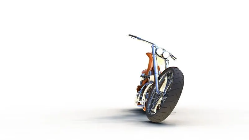
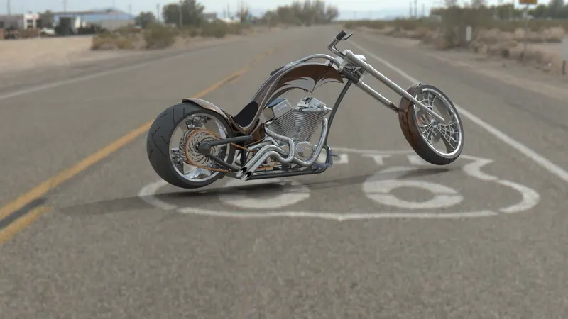
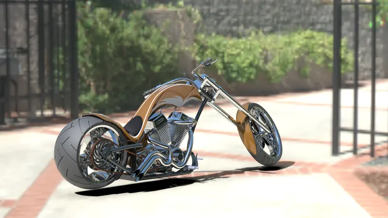
Some rendered images of chopper are attached below:
CONCLUSION
-
A model has been developed with the help of Solidworks by using some global variables, dimension and equation.
-
The components of the chopper are sketched and modelled in SolidWorks.
-
The components are placed into the setting of the assembly and assembled by applying the mates' chopper.
-
Using Photoview 360 & SolidWorks Visualize', the realistic image was rendered
-
The users can update model just by changing ground clearance, Tire size, etc.
-
In this way designer can perform tasks especially in the mechanical design.
-
After this user are comfortable to design and modify different components.